
Related Manuals for R2Sonic 2022

Summary of Contents for R2Sonic 2022
- Page 1 SONIC 2024/2022 BROADBAND MULTIBEAM ECHOSOUNDERS Operation Manual V3.0 Part No. 96000001...
- Page 2 Page 2 of 133 Version r000 Date 25-08-2010 Part No. 96000001...
- Page 3 Copyright license R2Sonic LLC is solely responsible for the content of this manual. Neither this manual, nor any part of this manual, may be copied, translated, distributed or modified in any manner without the express written approval of R2Sonic LLC.
- Page 4 This page intentionally left blank Page 4 of 133 Version r000 Date 25-08-2010 Part No. 96000001...
-
Page 5: Table Of Contents
Mounting the Sonic 2024/2022 Receive Module ............22 3.1.2 Receive Module ......................22 3.1.3 Mounting the Projector ....................24 3.1.4 Correct Orientation of the Sonic 2024 and Sonic 2022 ..........25 Sonar Head Installation Guidelines ..................26 3.2.1 Introduction ........................26 3.2.2 Over-the-Side mount ....................26 3.2.3... - Page 6 5.1.5 Motion Input ......................... 38 5.1.6 SVP input ........................38 OPERATION OF THE SONIC 2024/2022 VIA SONIC CONTROL ..........39 Installing Sonic Control Graphical User Interface ..............39 Network Setup ........................40 6.2.1 Initial Computer setup for Communication ..............40 6.2.2...
- Page 7 Sonic 2024/2022 Sonar Head Block Diagram ............... 67 Sonic 2024/2022 Transmit (Normal Operation Mode) ............68 Sonic 2024/2022 Receive (Normal Operation Mode) ............69 Sonic 2024/2022 Sonar Interface Module (SIM) Block Diagram .......... 71 7.4.1 Sonar Interface Module (SIM) Block Diagram .............. 71...
- Page 8 Appendices Appendix I: Multibeam Survey Suite Components Auxiliary Sensors and Components ..................73 Differential Global Positioning System .................. 73 8.1.1 Installation ........................73 8.1.2 GPS Calibration......................74 Gyrocompass ......................... 75 8.2.1 Gyrocompass Calibration Methods ................75 The Motion Sensor ........................ 80 Sound Velocity Probes ......................
- Page 9 Horizontal Measurement ..................... 94 10.2.3 Vertical Measurement ....................94 Appendix IV: The Patch Test 11 Introduction .......................... 97 11.1 Orientation of the Sonic 2024/2022 Sonar Head ..............97 11.2 Patch Test Criteria ........................ 98 11.2.1 Latency Test ........................98 11.2.2 Roll Test ........................
- Page 10 Type Definitions ......................113 13.2.3 Command Packet Format ................... 113 13.3 R2Sonic Head Commands – Binary Format ................. 114 13.4 R2Sonic SIM Commands – Binary Format ................115 Appendix VI: R2Sonic Data Formats 14 R2Sonic Uplink Data Formats ....................117 14.1...
- Page 11 Figure 10: Insert short threaded side of bolt in pass-through and tighten to receiver face ....22 Figure 11: Seated connectors (Sonic 2024 on left and Sonic 2022 on right) ........23 Figure 12: Receive Module with cables connected ................23 Figure 13: Position the insulating bushing, then wrap threads with Teflon tape, then secure with flat washer, locking washer and then nut ....................
- Page 12 Figure 39: Ping Rate Limit ........................46 Figure 40: Sector Coverage ........................47 Figure 41: Sector Rotate ........................48 Figure 42: Mission Mode ........................49 Figure 43: Roll Stabilize ........................49 Figure 44: Dual Head Mode ......................... 50 Figure 45: Dual Head Mode active ....................... 50 Figure 46: Load Settings menu selection .....................
- Page 13 Figure 96: Sonic 2024 Mounting Bracket Drawing 1 ................127 Figure 97: Sonic 2024 Mounting Bracket Drawing 2 ................128 Figure 98: Sonic 2022 Mounting Bracket Drawing 1 ................129 Figure 99: Sonic 2022 Mounting Bracket Drawing 2 ................130 Figure 100: Sonic 2024/2022 Mounting Bracket Flange ..............
- Page 14 List of Tables Table 1: Metric to Imperial conversion table ..................16 Table 2: System Specification ......................17 Table 3: Component Dimensions and Mass..................17 Table 4: Electrical Interface ......................... 18 Table 5: Ping Rate table ........................18 Table 6: Deck Lead Pin Assignment (Gigabit Ethernet and Power) ............. 36 Table 7: DB-9M RS-232 Standard Protocol ..................
-
Page 15: Introduction
Data Collection Computer (DCC). The Sonic 2024 and Sonic 2022 work on a user selectable frequency range of 200 kHz to 400 kHz so it is adaptable to a wide range of survey depths and conditions. The user can adjust the operating frequency, via the Sonic Control GUI, on the fly, without having to shut down the sonar system or change hardware or halt recording data. -
Page 16: How To Use This Manual
This manual is designed to cover all aspects of the installation and operation of the Sonic 2024 and Sonic 2022. It is, therefore, recommended that the user read through the entire Operation Manual before commencing the installation or use of the equipment. -
Page 17: Sonic Specifications
100 metres (3000 metres optional) Operating Temperature 0° C to 40° C Storage Temperature 0° C to 55° C Table 2: System Specification 2.2 Sonic 2022 System Specification System Feature Specification Frequency 400kHz / 200kHz Beamwidth – Across Track 1.0°@ 400kHz / 2.0° @ 200kHz Beamwidth –... -
Page 18: Sonic 2022 Dimensions And Weights
90 – 260 VAC; 45 – 65 Hz Power Consumption (SIM and Sonar Head) 75 Watt (Sonic 2022: 54 Watt) Power Consumption (Sonar Head Only) 50W avg.; 90W Peak (Sonic 2022: 35W avg.; 70W Peak) Uplink/Downlink 10/100/1000Base-T Ethernet Data Interface... -
Page 19: Acoustic Centre
2.7 Acoustic Centre Figure 2: Sonic 2024 Acoustic Centre Figure 3: Sonic 2024 Acoustic Centre as Mounted Centre of Flange to Alongship offset = 181.6mm Top of Flange to Z reference = 327.3mm Page 19 of 133 Version r000 Date 25-08-2010... -
Page 20: Figure 4: Sonic 2022 Acoustic Centre
Figure 4: Sonic 2022 Acoustic Centre Figure 5: Sonic 2022 Acoustic Centre as Mounted Centre of Flange to Alongship offset = 181.6mm Top of Flange to Z reference = 327.3mm Page 20 of 133 Version r000 Date 25-08-2010 Part No. 96000001... -
Page 21: Sonic 2024/2022 Sonar Head Installation - Surface Vessel
3 SONIC 2024/2022 SONAR HEAD INSTALLATION – Surface Vessel The Sonic 2024/2022 can be installed on an over-the-side pole, through a moon pool, or as a permanent hull mount. The light weight, small size, and low power consumption makes the Sonic 2024/2022 ideal for underwater vehicle (ROV and AUV) installations. -
Page 22: Mounting The Sonic 2024/2022 Receive Module
3.1.1 Mounting the Sonic 2024/2022 Receive Module Sonic 2024 Sonic 2022 Figure 7: Top side of Receive Module Sonic 2024 Sonic 2022 Figure 8: Receive Module Face The Receive Module is held to the mounting frame by 4 pass-through bolts, which are threaded on both ends. -
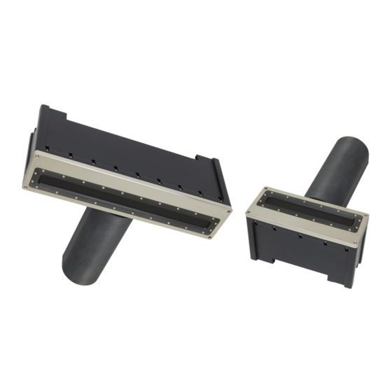
Page 23: Figure 11: Seated Connectors (Sonic 2024 On Left And Sonic 2022 On Right)
Figure 11: Seated connectors (Sonic 2024 on left and Sonic 2022 on right) Sonic 2024 Sonic 2022 Figure 12: Receive Module with cables connected Next, mount the Receive Module in the mounting frame. This can be most easily done by putting the receive module face on a piece of cardboard or other material and then lowing the mounting frame down with the threaded bolts passing through the mounting frame. -
Page 24: Mounting The Projector
A very light spray of silicon lubricant will aid seating the connector. Figure 15: Projector Stand-off Figure 14: Sonic 2024 Projector Sonic 2024 Sonic 2022 Figure 16: Mounting the projector Page 24 of 133 Version r000 Date 25-08-2010 Part No. -
Page 25: Correct Orientation Of The Sonic 2024 And Sonic 2022
3.1.4 Correct Orientation of the Sonic 2024 and Sonic 2022 The Sonic 2024/2022 is designed to be installed with the projector facing forward, or towards the bow. However, if the installation requires the projector to face aft, in Sonic Control, the user can select the orientation to projector aft and this will re-orientate the data output to reflect the projector orientation. -
Page 26: Sonar Head Installation Guidelines
3.2 Sonar Head Installation Guidelines 3.2.1 Introduction The proper installation of the Sonic 2024/2022 sonar head is critical to the quality of data that will be realised from the system. No matter the type of installation (hull mount, moon pool, or over-the- side pole), the head must be in an area of laminar flow over the array. -
Page 27: Moon Pool Mount
3.2.5 ROV Mounting The Sonic 2024/2022 is ideal for undersea operations due to its compact size and low power consumption. With all processing being done in the Receive Module, all that is required is to provide Ethernet over single mode fibre optic communication, between the SIM and the Receive Module. - Page 28 This page intentionally left blank Page 28 of 133 Version r000 Date 25-08-2010 Part No. 96000001...
-
Page 29: Sonic 2024/2022 Mounting: Sub-Surface (Rov/Auv)
100BASE link. • Average power, for a Sonic 2024 is 50W (1A), peak is 100W (2A); for a Sonic 2022 it is 35W (0.73A), peak is 75W (1.5A). The peak power of 100W (75W) occurs just after transmit and typically lasts for a few ms (depends on transmitter power setting). -
Page 30: Ethernet Wiring Considerations
4.1.1 Ethernet wiring considerations The sonar head and SIM use gigabit Ethernet ports. There are rules, regarding number of pairs of wire to use, between different Ethernet ports, those rules are: • Gigabit to Gigabit Need all four pairs. If only two pairs used, in an attempt to force the ports to 100BASE-T, the ports will not negotiate and the result will be no connection. -
Page 31: Rov Installation Examples
4.2 ROV Installation Examples Figure 20: Single Head ROV Installation scheme A Figure 21: Single Head ROV Installation scheme B (Preferred) Page 31 of 133 Version r000 Date 25-08-2010... -
Page 32: Figure 22: Dual Head Rov Installation Scheme A
Figure 22: Dual Head ROV Installation scheme A Figure 23: Dual Head ROV Installation scheme B (Preferred) Page 32 of 133 Version r000 Date 25-08-2010 Part No. 96000001... -
Page 33: Sonic 2024/2022 Sonar Interface Module (Sim) Installation And Interfacing
SIM to be passed onto the sonar head. 5.1.1 Physical installation The 15 metre cable, from the Sonic 2024/2022 Receive Module, connects directly to the SIM via an Amphenol ™ style connector. Therefore, the SIM must be located within 15 metres of the sonar head (a 50 metre cable is an option). -
Page 34: Electrical And Interfacing
Pass through holes Figure 25: Removal of trim to expose securing holes 5.1.2 Electrical and Interfacing The SIM has four DB-9 male connectors on the front. The label, on the top, clearly shows all connections. Beginning on the left front, the connections are: GPS, Motion, Heading, and Sound Velocity. -
Page 35: Figure 26: Sim Interfacing Physical Connections
Figure 26: SIM Interfacing Physical Connections Figure 27: SIM Interfacing Guide (from label on top of the SIM) NB. Again, at the present time, the SIM only takes in the PPS, NMEA Time message, sound velocity and motion data and not heading information. Page 35 of 133 Version r000... -
Page 36: Figure 28: Sim Iec Mains Connection And Deck Lead Amphenol Connector
Figure 28: SIM IEC mains connection and deck lead Amphenol connector Figure 29: Impulse connector Impulse Amphenol MS R2Sonic 10013A Function Pin Number Pin Number Wire Colour Data 1+ Blue Data 1- Blue/White Data 2+ Green Data 2- Green/White Data 3+... -
Page 37: Serial Communication
5.1.4.1 Connecting PPS and Time to the SIM In order to provide the most accurate multibeam data possible, the Sonic 2024/2022 takes in the GPS Pulse Per Second (PPS) and NMEA ZDA time message or an ASCII UTC message, which is associated with the pulse, to accurately time stamp the Sonic 2024/2022 data. -
Page 38: Motion Input
timing information. If both the ZDA and UTC are input, the UTC will take priority; the SIM will automatically ignore ZDA while receiving UTC. The UTC status code (‘ab’) is ignored. Setting up the time synchronisation is done through the Sonic Control software detailed in Chapter In that each of the SIM serial ports provides 12VDC on selected pins, it is not recommended to use a fully wired serial interface cable as this may cause some GPS receivers to stop sending data. -
Page 39: Operation Of The Sonic 2024/2022 Via Sonic Control
Sonic Control is supplied on a CD or as an attached file. There is no installation program, merely decompress the program to a folder in a root directory of the computer. Send the R2Sonic.exe to the desktop, as short cut,... -
Page 40: Network Setup
6.2 Network Setup All communication, between the Sonic 2024/2022 and the SIM and data collection computer is via Ethernet. The first step in setting up the sonar system is to establish the correct Ethernet parameters, which include the IP (Internet Protocol), Subnet Mask and UDP (User Datagram Protocol)base port under Settings | Network settings. -
Page 41: Discover Function
Sonar 1, in the Sonic Control 2000 Network settings. Use the Discover function to request the serial number information from all attached R2Sonic equipment. The Discover function will automatically transfer the serial numbers to the correct field. -
Page 42: Configuring Network Communication
Figure 34: Sonic Control Network setup Until the correct serial numbers are entered, there will be no communication. Once the correct serial numbers are entered, click Apply and dots will be visible in the wedge display signifying communication is established. Using Discover will guarantee that the serial numbers will be entered correctly and verify Ethernet communication between devices. -
Page 43: Figure 35: Command Prompt-Ipconfig/All
If the GUI IP number and subnet mask are set correctly, the Discover button will list the R2Sonic devices attached to the network. If the GUI IP number and/or subnet mask is set wrong, Discover will not work and the sonar head and SIM will not configure. -
Page 44: Sensor Setup (Serial Interfacing)
6.3 Sensor Setup (Serial Interfacing) The Sonar system receives various data on the SIM serial ports as noted in Section 5. Select Settings | Sensor setting to setup the serial communications parameters. Figure 36: Sensor communication settings 6.3.1 GPS The GPS input is for the ZDA time message ($GPZDA) or Trimble UTC message, other NMEA messages may be in the same string;... -
Page 45: Motion
Used to receive or send synchronisation TTL pulses. This is under development. 6.4 Sonar Settings The Sonic 2024/2022 has many features that provide the user with the versatility to tailor the system to any survey project; these features can be controlled either through the Operation Settings or with the mouse cursor. -
Page 46: Frequency
6.4.2 Ping Rate Limit The Sonic 2024/2022 can transmit at a rate up to 60 Hz (60 pings per second), this is called the Ping Rate. At times, it may be desirable to reduce the ping rate to reduce the collection software file size or for other reasons. -
Page 47: Sector Coverage
6.4.3 Sector Coverage The Sonic 2024/2022 allows the user to select the swath sector from 10° to 160°. All 256 beams are used, no matter what the selected sector coverage that is chosen. The smaller the sector, the higher the sounding density is within that sector. Changing the Sector Coverage can be done on the fly, with no need to stop recording data or to go offline. -
Page 48: Bottom Sampling
Coverage) equal to, or less than, 130°. 6.4.6 Mission Mode The versatility, built into the Sonic 2024/2022, is further enhanced with the ability to adapt the system to the nature of the survey task: normal survey or surveying a vertical feature. There are two Mission Modes: •... -
Page 49: Roll Stabilize
The R2Sonic roll stabilisation has been developed based on recommend methods from various data collection software companies. -
Page 50: Dual Head Mode
6.4.8 Dual Head Mode The selections are: Single Head, Simultaneous Ping or Alternating Ping. When the dual head mode is selected, a second wedge display will be available in Sonic Control 2000. Figure 44: Dual Head Mode Figure 45: Dual Head Mode active In dual head mode, certain controls: Range, Power, Pulse Length, and Gain set both sonar heads. -
Page 51: Figure 46: Load Settings Menu Selection
Figure 46: Load Settings menu selection The available settings files will be shown. There are two Factory Default initialisation files; one for single head, the other for dual head. Figure 47: Selecting Factory default settings file for dual head operation When the file is loaded, Sonic Control will be configured for dual head mode, this includes the default network settings. -
Page 52: Snippets Enable
Figure 48: Default dual head network settings 6.4.9 Snippets Enable If the Snippet option is installed in the Sonic 2024/2022, the Snippets can be turned on and off by ticking the box next to Snippets Enable. 6.4.10 Mount 6.4.10.1 Projector Orientation The preferred orientation is with the projector facing forward. - Page 53 Please contact R2Sonic for further guidance on mounting the projector with a different vertical offset. 6.4.10.3 Head Tilt If the sonar head is physically tilted to port or starboard, the tilt angle is entered here to rotate the wedge and depth gates.
-
Page 54: Ocean Setting
6.5 Ocean Setting Figure 49: Ocean Characteristics Ocean Characteristics include Absorption and Spreading loss, which are the main components of the Time Variable Gain (TVG) computation, and Sound Velocity (for receive beam steering). 6.5.1 Absorption: 0 – 120dB/km Absorption is influenced primarily by frequency and the chemical compounds of boric acid B(OH) and magnesium sulphate MgSO It is highly recommended that the local absorption value be entered. -
Page 55: Time Variable Gain
6.5.3 Time Variable Gain Absorption and spreading loss are the main components of the Time Variable Gain (TVG) computation. TVG Equation TVG = 2*R*a/1000 + Sp*log(R) + G α = Absorption Loss db/km = Range in metres = Spreading loss coefficient = Gain from Sonar Control setting TVG is employed in underwater acoustics to compensate for the nature of the reflected acoustic energy. - Page 56 Therefore, for accurate beam steering to take place, an accurate sound velocity must be provided to the Sonic 2024/2022. Page 56 of 133 Version...
-
Page 57: Tools | Firmware Upgrade
8 would have no delay; thus a ‘virtual array’ will be formed. 6.6 Tools | Firmware Upgrade When R2Sonic issues a firmware upgrade, it will be made available to the customer, allowing the customer to upgrade their system by themselves. There are two firmware upgrades possible: SIM upgrade and/or sonar head upgrade. -
Page 58: Figure 53: Select Correct Upgrade .Bin File
Figure 53: Select correct upgrade .bin file Once the Update button is clicked on, a batch file will automatically run and download the .bin to the appropriate place. Figure 54: A batch file will automatically load the upgrade file Figure 55: Message displayed when the upgrade process is complete Page 58 of 133 Version r000... -
Page 59: Figure 56: Error If Wrong File Chosen For Upgrade
There are two cases where the upgrade process may fail; one is if the wrong type of file is selected, the other is if there is no communication with the part of the sonar that is to be upgraded. Each instance will provide an error message. -
Page 60: Display Settings
Main Operation Parameters The main operating parameters of the Sonic 2024/2022 are controlled by the buttons in the lower portion of the window. Figure 59: Operating parameter buttons To change a value, position the mouse cursor on the button then use the left mouse button to decrease the value and the right mouse button to increase the value. -
Page 61: Range: 0 - 500 Metres
Sonic 2024/2022 can transmit; this is the Ping Rate. What the range setting is doing is telling the Sonic 2024/2022 the length of time that the receivers should be ‘listening’ for the reflected acoustic energy. If the Range setting is too short, some of the returning energy will be received during the subsequent receive period, i.e. -
Page 62: Pulse Length: 15Μsec - 500Μsec
increase the strength of the bottom returns and, thus, allow for a lower receiver gain setting. If too much power is used, the receivers can be over-driven (saturated); this will result in noisy data and/or erroneous nadir depth readings. A good balance of source level (Power) and receiver gain is the desired end. -
Page 63: Figure 62: Depth Gates On And Off Control
If the minimum or maximum depth gate eliminates good data, the data are lost as it will not be included in the Sonic 2024/2022 output. In the data collection software there will also be a form of depth gates. If the data are eliminated there, it is more than likely that the data is flagged and not really deleted, so it can be recovered. -
Page 64: Save Settings
Although the user enters a depth for the gate setting, to the Sonic 2024/2022 this is a time to start searching and a time to stop searching. Figure 64: Graphical representation of depth gate The above representation illustrates how the depth gate narrows down the bottom detection search area (in time) to only the area where the true bottom is expected. -
Page 65: Operating Sonic Control On A Second Computer
IP addresses as well as UDP ports. By doing Discover (in Settings | Network Settings), the system looks for all attached R2Sonic equipment, which will be indentified by model and serial number. Once the serial number is discovered, it is used to assign an IP and UDP port to the sonar head and the SIM, after this is done, the IP and UDP ports can be changed. -
Page 66: Changing Back To One Computer
Figure 65: Change in GUI IP 6.10.2 Changing back to one computer 1) Open Sonic Control on the data collection computer. 2) Change the GUI address to 10.0.1.102 3) On the second computer, change the GUI IP address back to 10.0.1.102 and Apply. 4) Sonic Control, on the data collection computer now controls the system. -
Page 67: Sonic 2024/2022 Theory Of Operation
7 SONIC 2024/2022 THEORY OF OPERATION The Sonic 2024/2022 transmits a shaped continuous wave pulse at the user- selected frequency. The transmit pulse is narrow in the along-track direction, but very wide in the across-track direction. The reflected acoustic energy is received via the Sonic 2024/2022 receivers; within the Receive Module the beams are formed and the bottom detection process takes place. -
Page 68: Sonic 2024/2022 Transmit (Normal Operation Mode)
Depending on the water conditions, sea floor composition and other factors, a portion of the acoustic energy that strikes the seafloor will be reflected back towards the surface. The return acoustic energy will strike the Sonic 2024/2022 receiver’s ceramics. Page 68 of 133... -
Page 69: Sonic 2024/2022 Receive (Normal Operation Mode)
7.3 Sonic 2024/2022 Receive (Normal Operation Mode) The Projector is comprised of composite ceramics that convert electrical energy to acoustic energy. The composite ceramics, in the Receive Module, convert the reflected acoustic energy back to electrical energy. The small electrical voltage, generated by the ceramics, is amplified and then passed onto the receivers. - Page 70 This page intentionally left blank Page 70 of 133 Version r000 Date 25-08-2010 Part No. 96000001...
-
Page 71: Sonic 2024/2022 Sonar Interface Module (Sim) Block Diagram
The SIM operates within a voltage range of 90 to 260 VAC. The mains voltage is converted in the various DC voltages required for the operation of the Sonic 2024/2022. Primarily, 48 VDC is sent to the Receive Module to power the sonar head. - Page 72 This page intentionally left blank Page 72 of 133 Version r000 Date 25-08-2010 Part No. 96000001...
-
Page 73: Appendix I: Multibeam Survey Suite Components
Components 8 Auxiliary Sensors and Components A multibeam survey system is comprised of more components than just the Sonic 2024/2022 Multibeam Echosounder. These components are the auxiliary sensors, which are required to provide the necessary information for a multibeam survey. This does not mean that these sensors are a minor part of the survey system;... -
Page 74: Gps Calibration
during survey operations. If mounting the antenna on a vessel that has helicopter landing facilities, coordinate the placement of the antenna with the personnel in charge of helicopter operations. When the location for the antennae has been determined the next step is determining how the coaxial cable, connecting the antenna and the receiver, is to be run. -
Page 75: Gyrocompass
The two main causes of error, in this area, are: • Wrong geodetic transformations being applied to the WGS-84 position derived from GPS. • Erroneous coordinates for the Differential reference station. 8.1.2.2 Position Accuracy Determination Method 2 This method is most easily accomplished during the gyrocompass calibration. The antenna remains mounted on the vessel. - Page 76 8.2.1.1 Standard Land Survey Technique One of the most accurate methods to determine the gyro error involves the use of standard recognised land survey techniques. The time and equipment involved requires that a substantial period be allotted for such a calibration. •...
-
Page 77: Figure 70: Gyrocompass Calibration Method 1
If physical adjustments are required, they should be made and the calibration process repeated. If the adjustment is determined to be minor and can be accounted for in the survey software, the correction value should be entered and then verified using the calibration process. This check of the calibration value can be an abbreviated version of the calibration process detailed above. -
Page 78: Figure 71: Gyro Calibration Method 2
8.2.1.2 Tape and Offset Method of Gyro Calibration This method relies on measuring the offset distance from a baseline on the quay, with a known azimuth, to a baseline that is established on the vessel. There are greater areas for error when using this method, particularly in establishing a baseline with known azimuth. -
Page 79: Figure 72: Gyro Calibration Method 2 Example
The example, below, will illustrate the math involved. Figure 72: Gyro Calibration Method 2 example A to A' 1.0 metres B to B' 1.5 metres Side a 5.0 metres Side b 1.5 – 1.0 = 0.5 metres Angle b' Arctan 0.5/5.0 = 5.7° Ship Azimuth = 270°... -
Page 80: The Motion Sensor
8.3 The Motion Sensor The motion sensor is used to determine the attitude of the vessel in terms of pitch, roll and heave. Pitch is the movement of the bow going up and down. Roll is the movement of the port and starboard side going up and down. -
Page 81: Sound Velocity Probes
The motion sensor should be mounted on as level a platform as possible. After mounting the motion sensor, the actual 'mounting angles' should be measured. Some motion sensors contain internal programs that can measure the mounting angles. Some data collection software packages also include the capability to measure mounting angles. -
Page 82: Ctd Probes
The CTD and Time of Flight probes store the data internally. The data is downloaded to a computer after the probe is recovered. 8.4.1 CTD Probes The CTD probe type of sound velocity probe has instruments to measure the conductivity of the water, water temperature, and a pressure sensor to measure depth. -
Page 83: Time Of Flight Probe
2, and the sound velocity determined. The Time of Flight probe is usually considered more accurate for multibeam survey work. The sound velocity probe that is mounted close to the Sonic 2024/2022 sonar head is a time of flight probe. -
Page 84: The Sound Velocity Cast
and are used extensively by Navy and Defence forces for rapid determination of the sound velocity without stopping the vessel. 8.5 The sound velocity cast There are no set rules for when to take a measurement of the water column sound velocity. Common sense is a good guideline. - Page 85 5. Secure the bitter end of the downline to the vessel. 6. Request permission, from the bridge or helm, to deploy and await their OK to launch. a. Bridge or helm to ensure that the vessel is out of traffic. b.
-
Page 86: Figure 76: Deploying A Sound Velocity Probe Via A Winch Or A - Frame
Figure 76: Deploying a sound velocity probe via a winch or A - Frame The other major consideration when deploying a probe in deeper water, is that the vessel must be stationary longer and will drift. If there is a large variation in depths, the depth when the probe went in, may not be the same depth when the probe reaches the bottom. -
Page 87: Appendix Ii: Multibeam Surveying
APPENDIX II: Multibeam Surveying 9 Introduction Multibeam surveying affords the surveyor with many advantages, but it also requires more thought behind the survey itself. 9.1 Survey Design Multibeam surveying survey planning is very different than single beam survey planning. The main considerations are line spacing and line direction. -
Page 88: Line Run-In
In setting up the survey lines, if the lines were to run up and down slope, the spacing would have to vary between the start and the end of the lines, as the swath coverage would vary due to the change in water depth. -
Page 89: Daily Survey Log
The vessel record is meant to be a quick reference for general information that is required for multibeam surveying. Some of the information does not change from survey to survey and should go either in the front of the book or the back of the book. A section of pages can then be devoted to the information that does change from survey to survey or day to day. -
Page 90: Date 25-08-2010 Part No
A copy of the survey log is sent along with the multibeam data to processing and a copy is kept on board the vessel. An example of the information on a smooth log: • Sensor offsets • Calibration offsets • Date •... -
Page 91: Figure 77: Rough Log, Kept During Survey Operations
Figure 77: Rough log, kept during survey operations...does not need to be neat, but must contain all pertinent information Page 91 of 133 Version r000 Date 25-08-2010... -
Page 92: Figure 78: Smooth Log; Information Copied From Real-Time Survey Log
Figure 78: Smooth log; information copied from real-time survey log... -
Page 93: Appendix Iii: Offset Measurement
Each component or sensor that produces information, unique to its position, will have a point that is considered the reference point of that sensor. The Sonic 2024/2022, the motion sensor, and the GPS antenna will have a documented point from which to measure. The gyrocompass’ data is not dependent on its position on the vessel so, therefore, does not require an offset measurement. -
Page 94: Measuring Offsets
Please refer to the drawings on Page 104 to 106 to obtain measurements, with reference to the system offsets, when mounting on the Sonic mounting frame. Figure 80: Sonic 2024/2022 Acoustic Centre 10.2.2 Horizontal Measurement All measurements should be made with a metal tape measure. A cloth tape can stretch, it can also be knotted or kinked, unknown to the persons making the measurements. - Page 95 The plumb bob works, of course, by gravity so generally points to the centre of the earth. This being the case, if the vessel is not in good trim, i.e. has a list, the resting position of the plumb bob may not be at the true vertical point under the place from which it is being held.
- Page 96 This page intentionally left blank Page 96 of 133 Version r000 Date 25-08-2010...
-
Page 97: Appendix Iv: The Patch Test
APPENDIX IV: The Patch Test 11 Introduction The alignment of the Sonic 2024/2022 sonar head to the motion sensor and gyro is critical to the accuracy of the determined depths. It is not possible to install the sonar head in exact alignment with the motion sensor and gyro to the accuracy required (x.xx°). -
Page 98: Patch Test Criteria
11.2 Patch Test Criteria The patch test requires collecting sounding data over two distinct types of sea floor topography; a flat bottom is used for the roll computation whereas a steep slope or feature is used for the latency, pitch, and yaw data collection. Care must be taken that the sonar head covers the same area on both data collection runs, this may not be the same as vessel position, especially with an over-the-side mount or if the sonar head rotated. -
Page 99: Roll Test
11.2.2 Roll Test The data collection for roll has to be over a flat sea floor. One line is surveyed twice, in reciprocal directions and at survey speed. When the data, from the two data collections, are looked at in profile, there will be two seafloors sloped in opposite directions. -
Page 100: Pitch Test
11.2.3 Pitch Test The pitch data collection is over the same type of sea floor as the latency data collection, i.e. steep slope or feature on the sea floor. One line is surveyed, twice, in reciprocal directions at survey speed. It is very critical that the sonar head passes over the same exact part of the slope on each run. -
Page 101: Yaw Test
11.2.4 Yaw Test The yaw data collection and subsequent solving for the yaw offset is usually the most difficult of the 4 tests that comprise a patch test. This is especially true if a slope is used for the yaw computation; a feature generally works much better. -
Page 102: Solving For The Patch Test
The resultant patch test values are corrections that are entered in the data collection software and not in the Sonic 2024/2022 software, as the values are used for process data. Page 102 of 133 Version... -
Page 103: Introduction
APPENDIX V: Basic Acoustic Theory Figure 87: In 1822 Daniel Colloden used an underwater bell to calculate the speed of sound under water in Lake Geneva, Switzerland at 1435 m/Sec, which is very close to recent measurements. 12 Introduction With multibeam, as with any echosounder, a main concern is: sound in water. Once the projector transmits the acoustic energy into the water, many factors influence that energy’s velocity and coherence. -
Page 104: Figure 88: Concept Of Refraction Due To Different Sound Velocities In The Water Column
Figure 88: Concept of refraction due to different sound velocities in the water column The velocity of sound in water varies both horizontally and vertically. It cannot be assumed that the velocity of sound in the water column remains constant over large areas or throughout the day in a more local area. -
Page 105: Salinity
12.1.1 Salinity Generally, salinity ranges from 32 – 38 parts per thousand (ppt) in ocean water. A change in salinity will create density changes, which affect the velocity of sound. As a general rule, a change in salinity of only 1 ppt can cause a sound velocity change of 1.4m/sec. There are many influences on the salinity concentration in sea water. -
Page 106: Transmission Losses
12.2 Transmission Losses The transmission of an acoustic pulse is generally called a ‘ping’. When the projector sends out the acoustic pulse many factors operate on that pulse as it moves through the water column to the bottom and also on its return upward. The major influence of the water column sound velocity characteristics was detailed above;... -
Page 107: Absorption
Figure 92: Concept of Cylindrical Spreading 12.2.2 Absorption Absorption is frequency dependent and refers to the conversion of acoustic energy to heat when it strikes chemically distinct molecules in the water column. Magnesium Sulphate MgSO predominates, with Boric Acid B(OH) playing a major part at lower frequencies. -
Page 108: Table 10: Absorption Values For Seawater And Freshwater At 400 Khz And 200 Khz
The below table and charts illustrate how frequency, water temperature, and salinity affect absorption Seawater Absorption Values: Salinity = 35ppt, pH=8 dB/km 400kHz 200kHz Temp (C) 5° 10° 15° 20° 25° 5° 10° 15° 20° 25° Depth (m) 97 100 111 130 154 96 100 110 128 153 99 110 128 152 99 109 127 151... -
Page 109: Graph 5: Seawater Absorption (Salinity 35Ppt)
Frequency and Temperature Influence on Seawater Absorption 400kHz 200kHz Mean values for water depths from 50 metres to 300 metres (400 metres for 200 kHz) Degrees Celsuis 5° 10° 15° 20° 25° Graph 5: Seawater Absorption (Salinity 35ppt) Frequency and Temperature Influence on Freshwater Absorption 400 kHz 200 kHz... -
Page 110: Table 11: Operating Frequency - Water Temperature - Absorption
Seawater Absorption db/km Freq. 10°C 15°C 20°C 25°C Table 11: Operating Frequency - water temperature - absorption Page 110 of 133 Version r000 Date 25-08-2010 Part No. 96000001... -
Page 111: Reverberation And Scattering
(backscatter); this can be a cause for ‘noise’ in the sonar data. Again, the surveyor should be aware of this condition and, if need be, change the operating parameters of the Sonic 2024/2022. When discussing the changing of the operating parameters, it is generally a matter of increasing transmit power or pulse length to get more total power into the water. - Page 112 This page intentionally left blank Page 112 of 133 Version r000 Date 25-08-2010...
-
Page 113: R2Sonic Control Commands
13 R2Sonic Control Commands 13.1 Introduction The Sonic 2024/2022 is configured and control using a set list of commands. Sonic Control works by sending these commands to system. The control commands, provided here, can be used to control the Sonic 2024/2022. This describes the commands sent from the user interface to the sonar head and SIM. -
Page 114: R2Sonic Head Commands - Binary Format
13.3 R2Sonic Head Commands – Binary Format Cmd Format Units Values Description ABS0 dB/km 0 to 200 absorption BIE0 0 = off bathy intensity enable 1 = on BMAX metres 0 to 999 max range filter head default = 999... -
Page 115: R2Sonic Sim Commands - Binary Format
0 to 500μs TXP0 0, 191 to 221 power dB//1μPa TWIX 0 = flat bottom bottom type 1 = vertical features 13.4 R2Sonic SIM Commands – Binary Format Format Units Values Description BDG0 standard baud rates GPS baud 300 to 115200 BDM0... - Page 116 This page intentionally left blank Page 116 of 133 Version r000 Date 25-08-2010...
-
Page 117: R2Sonic Uplink Data Formats
Appendix VII: R2Sonic Data Format 14 R2Sonic Uplink Data Formats 14.1 . Introduction This describes the data formats sent from the sonar head to the data collection software. The formats are given in pseudo C. Head firmware version 12-Apr-2010 utilise the data formats in this document. Head firmware version 25-Mar-2010-11-14-27 uses the bathymetry packet format described in this document. -
Page 118: Type Definitions
14.4 . Type Definitions typedef unsigned char u8; typedef unsigned short u16; typedef unsigned int u32; typedef signed char s8; typedef signed short s16; typedef signed int s32; typedef float f32; 14.5 . Bathymetry Packet Format // *** BEGIN PACKET: BATHY FORMAT 0 *** PacketName;... - Page 119 H0_RxGain; // [ΔH0_RxGain = 1; 2dB gain change] H0_RxSpreading; // [dB (times log range in meters)] H0_RxAbsorption; // [dB per kilometer] H0_RxMountTilt; // [radians] H0_RxMiscInfo; // to be determined H0_reserved; // reserved for future use H0_Points; // number of bathy points // section R0: 16-bit bathy point ranges R0_SectionName;...
- Page 120 // section G0: simple straight-line depth gates G0_SectionName; // 'G0' G0_SectionSize; // [bytes] size of this entire section G0_DepthGateMin; // [seconds two-way] G0_DepthGateMax; // [seconds two-way] G0_DepthGateSlope; // [radians] // section G1: 8-bit gate positions, arbitrary paths (present only during "verbose" gate description mode) G1_SectionName;...
-
Page 121: Snippet Format
14.6 . Snippet Format // *** BEGIN PACKET: SNIPPET FORMAT 0 *** PacketName; // 'SNI0' PacketSize; // may be zero in UDP, otherwise: [bytes] size of this entire packet DataStreamID; // reserved for future use // section H0: header (present only in first snippet packet of each ping) H0_SectionName;... - Page 122 // section S1: 16-bit snippet data (for network efficiency packet may contain several of these sections) // (supports snippets up to 32K samples by fragmenting at the IP level rather than by the application like 81xx) S1_SectionName; // 'S1' S1_SectionSize; // [bytes] size of this entire section S1_PingNumber;...
-
Page 123: Drawings
Figure 95: Sonic 2022 Mounting Bracket Drawing 2..................................130 Figure 96: Sonic 2024/2022 Mounting Bracket Flange ................................131 Figure 97: SIM Box Drawing ......................................... 132 Figure 98: R2Sonic Deck lead minimum connector passage dimensions ............................ 133 Page 123 of 133 Version... -
Page 124: Figure 93: Sonic 2024/2022 Projector
Figure 93: Sonic 2024/2022 Projector Page 124 of 133 Version r000 Date 25-08-2010 Part No. 96000001... -
Page 125: Figure 94: Sonic 2024 Receive Module
Figure 94: Sonic 2024 Receive Module Page 125 of 133 Version r000 Date 25-08-2010... -
Page 126: Figure 95: Sonic 2022 Receive Module
Figure 95: Sonic 2022 Receive Module Page 126 of 133 Version r000 Date 25-08-2010 Part No. 96000001... -
Page 127: Figure 96: Sonic 2024 Mounting Bracket Drawing 1
Figure 96: Sonic 2024 Mounting Bracket Drawing 1 Page 127 of 133 Version r000 Date 25-08-2010... -
Page 128: Figure 97: Sonic 2024 Mounting Bracket Drawing 2
Figure 97: Sonic 2024 Mounting Bracket Drawing 2 Page 128 of 133 Version r000 Date 25-08-2010 Part No. 96000001... -
Page 129: Version
Figure 98: Sonic 2022 Mounting Bracket Drawing 1 Page 129 of 133 Version r000 Date 25-08-2010... -
Page 130: Figure 99: Sonic 2022 Mounting Bracket Drawing 2
Figure 99: Sonic 2022 Mounting Bracket Drawing 2 Page 130 of 133 Version r000 Date 25-08-2010 Part No. 96000001... -
Page 131: Figure 100: Sonic 2024/2022 Mounting Bracket Flange
Figure 100: Sonic 2024/2022 Mounting Bracket Flange Page 131 of 133 Version r000 Date 25-08-2010... -
Page 132: Figure 101: Sim Box Drawing
Figure 101: SIM Box Drawing Page 132 of 133 Version r000 Date 25-08-2010 Part No. 96000001... -
Page 133: Figure 102: R2Sonic Deck Lead Minimum Connector Passage Dimensions
Figure 102: R2Sonic Deck lead minimum connector passage dimensions Page 133 of 133 Version r000 Date 25-08-2010...
Need help?
Do you have a question about the 2022 and is the answer not in the manual?
Questions and answers