
Subscribe to Our Youtube Channel
Related Manuals for micro-trak SPEED-O-METER 13347

Summary of Contents for micro-trak SPEED-O-METER 13347
- Page 1 SPEED-O-METER Accurate Digital Measurement Add digitally accurate measurement to any vehicle with a 12V power supply: ATV’s, tractors, industrial equipment, trucks, etc. Installation/Operator’s Manual...
- Page 2 If you do encounter a problem that cannot be corrected by reviewing this manual, consult your dealer or call our technical personnel for assistance. Toll Free in U.S. or Canada: (800) 328-9613 or (507) 257-3600 E-mail: trakmail@micro-trak.com Web: www.micro-trak.com Mfg. in U.S.A. 1305 Stadium Road Mankato, MN 56001-5355 © Copyright 2007 Micro-Trak Systems, Inc. Printed in the U.S.A.
-
Page 3: Warranty
* Some limitations apply. See warranty statement for details. At Micro-Trak Systems, we believe a product that delivers quality and performance at a low cost is what is needed to help today’s operator and the operator of the future compete in the world market. -
Page 4: Table Of Contents
Table of Contents Warranty........................................3 Table of Contents ....................................4 Installation ...................................... 5-12 Component Parts and Assembly Hardware ............................... 5 Required Tools ........................................6 Mounting the Display Console ..................................6 Electrical Installation ......................................7 Speed Sensor Installation ....................................7-11 Magnets ........................................... 8 Attaching Magnets to Hub ..................................8 ATV Wheels ........................................ -
Page 5: Component Parts And Assembly Hardware
Component Parts and Assembly Before beginning installation, check the carton contents for the following items: SPEED-O-METER Accurate Digital Measurement Add digitally accurate measurement to any vehicle with a 12V power supply: ATV’s, tractors, industrial equipment, trucks, etc. Installation/Operator’s Manual Speed-O-Meter Console Reference Manual Console Mount Kit P/N 13347... -
Page 6: Installation
Installation Required Tools Tools Needed to Install Speed-O-Meter Installation of your SPEED-O-METER is basically a three-step procedure. Each installation will vary somewhat, depending • Screwdrivers and Nutdriver on your type of equipment. Allowances for these differences • Electric Drill and Bits •... -
Page 7: Electrical Installation
Installation (cont) Electrical Installation The SPEED-O-METER must be connected to a 12-volt DC Locate the single BLUE wire supplied with the kit to make a electrical system. Using your test light, locate a terminal or ground wire. Crimp a female spade terminal on one end and wire connected to your ignition switch which is “hot”... -
Page 8: Magnets
Installation The magnets provided by Micro-Trak are marked with a (cont) punched dashed line on the SOUTH pole side of the magnet. Magnets See Illustration 4. Always use an even number of magnets, and always alternate Please read the following information about magnet spacing the polarities of the magnets as you go around the wheel and polarity. -
Page 9: Atv Wheels
Installation (cont) Illustration 7 ATV Wheels Cut Bracket Sensor Bracket to Clear Rim Refer to the following diagrams for specific mounting instructions. Magnets may be attached mechanically as Magnet Axle shown or adhered with epoxy or other high quality adhesive. When using adhesive, thoroughly clean the area of dirt and oil. -
Page 10: Implement Wheels
Hall-effect speed sen sor must alternate as Turn on remaining locking nut. Set sensor to proper the shaft is turned. The magnets provided by Micro-Trak are distance from magnets (1/4” to 1/2”, or 6mm to 13mm). -
Page 11: Optional Gas Engine Rpm Sensor Installation
Installation (cont) Optional Gas Engine RPM Sensor Installation The inductive sensor in this kit is ONLY for use on gas Illustration 9 engines. Secure the RPM sensor on any convenient spark RPM SENSOR plug wire with electrical tape or plastic ties. The white mark on the sensor must be positioned directly over the spark plug WHITE MARK wire. -
Page 12: Speed Sensor Options
Vansco Radar Speed Sensor or Dickey-John GPS speed sensors. An adapter cable may be required. Contact a Micro-Trak dealer/distributor for de tails on any of these products, or call Mi cro-Trak Systems, Inc. at 1-800-328-9613. Care and Maintenance of your SPEED-O-METER... -
Page 13: Console Functions
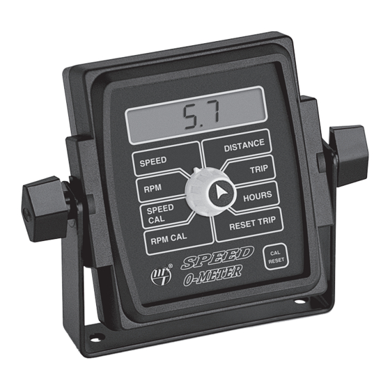
SPEED-O-METER Console Functions SPEED: DISTANCE: Displays ground speed in miles (kilometers) per hour. Displays total distance traveled. Cannot be reset. RPM: TRIP: Displays revolutions per minute. Displays distance traveled. May be reset. SPEED CAL: HOURS: Used for calibrating the speed sensor. Displays total hours of operation. -
Page 14: Calibration
The factory default is 1810, which is the number required steps. Follow these instructions to do so: for mile calculations using Micro-Trak’s ultrasonic Trak-Star (3.5 inches/pulse). For a wheel driven distance sensor, if the Turn the rotary switch to the “SPEED” position. Press distance (d) traveled between magnets passing under the and hold the “CAL/RESET”... -
Page 15: Rpm Calibration
Calibration RPM Calibration Follow these instruction for calibrating RPM: Illustration 12 Turn the rotary switch to the RPM CAL position. The display will show either a “2C” or a “4C” along with a small blinking CAL. See Illustration 12. MANAUTO •... -
Page 16: Optional Features
For Warning Devices requiring more than 1/2 amp the console. Turn the rotary switch to the “TRIP” position, (Micro-Trak Relay Kit P/N 01536) press the CAL/RESET button for three seconds. The small CAL indicator will begin flashing. Within three seconds turn... -
Page 17: Troubleshooting
(Console requires 12 volts for proper operation.) equipment failure, please DO NOT open the console. Your SPEED IS ALWAYS ZERO OR ERRATIC system is protected by a warranty and Micro-Trak will gladly Make sure that at least two magnets are installed, with correct any defect. -
Page 18: Checking Individual Components
Troubleshooting Individual Component Troubleshooting CONSOLE CONSOLE INPUTS The only way to field test a console is to connect it to a If there is no response from any of the following tests, refer to harness on a vehicle with a known working console or install the main wiring diagram on the previous page to locate the it on an E-POP (Electronic Point of Purchase) display stand. -
Page 19: Appendices
Appendices... -
Page 20: Appendix A: Radar "Y" Cables
Appendix A Radar “Y” Adapter Cables In-Cab John Deere Metri-Pack Connector RADAR CONNECTOR SIGNAL PIN 8000/9000 Series DICKEY-john Ground Signal Common Cannon DICKEY-john DICKEY-john Deutsch P/N 14810 DICKEY-john Ford Packard DICKEY-john In-Cab JD (8000 & 9000’s Metri-Pack Packard Magnavox & Phillips DICKEY-john Radar Amp Connector Raven Conxall... -
Page 21: Appendix B Conversion Tables
Appendix B Conversion Tables English to Metric Metric to English When You Know Multiple By To Find When You Know Multiple By To Find LINEAR MEASUREMENT LINEAR MEASUREMENT inches 25.4 millimeters millimeters .039 inches feet 0.305 meters meters 3.28 feet yards 0.914 meters... -
Page 22: Appendix C Parts List
Appendix C Parts List The following replacement parts are available from your dealer, or directly from: Micro-Trak Systems, Inc. P.O. Box 99 111 East LeRay Avenue Eagle Lake, MN 56024-0099 NOTE: When ordering parts, list the model and serial number of your console, and the description and part number of each part that you want to order. - Page 24 Manufactured in U.S. A. by 1305 Stadium Road, Mankato, MN 56001-5355 Toll-Free: 800-328-9613 507-257-3600 www.micro-trak.com • Email: trakmail@micro-trak.com Printed in U.S.A. © 2007 Micro-Trak Systems, Inc. • P/N 13245 Rev. 2...
Need help?
Do you have a question about the SPEED-O-METER 13347 and is the answer not in the manual?
Questions and answers