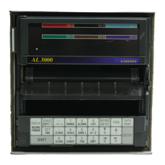
Chino AL3000 Series Instructions Manual
Ethernet communication interface
Hide thumbs
Also See for AL3000 Series:
- Instructions manual (116 pages) ,
- Instructions manual (76 pages)

Related Manuals for Chino AL3000 Series


Summary of Contents for Chino AL3000 Series
- Page 1 INST. No. INE-322B AL 3000/AH 3000 BR1000/SE 3000 SERIES ETHERNET COMMUNICATION INTERFACE...
-
Page 2: Table Of Contents
Contents Preface Outline Function 2.1 Protocol configuration 2.2 Ethernet IF Web page Explanation of each part Wirings Wirings Initial settings 5.1 Checking the LAN function of your PC 5.2 Network settings of your PC 5.3 Settings of Ethernet IF Operation 6.1 MODBUS 6.2 HTTP Appendix 1 Glossary... -
Page 3: Preface
Preface This instruction manual explains the specifications and instructions of the Ethernet communications interface for AL3000 series hybrid recorders, AH3000hybrid recorders, BR1000 series graphic recorders, and SE3000 series field scanners. For using this interface safely and preventing any troubles, make sure to read this instruction manual before operation. -
Page 4: Outline
Outline By connecting the Ethernet communications interface (Ethernet IF) for AL3000 series hybrid recorders, AH3000 series hybrid recorders, BR1000 series graphic recorders, SE3000 series field scanners with Local Area Network (LAN) configured by Ethernet (10BASE-T), you can browse real time data of the networked instruments and set up their parameters (partly) by using the WWW browser on your personal computer (PC) connected with the LAN. -
Page 5: Explanation Of Each Part
Explanation of each part Ethernet IF consists of one connector, one LED, and one push button switch. BR/AL/AH SE3000 (1) (2) The following functions are commonly available in the Ethernet IFs for BR1000/AL3000/AH3000 and for SE3000. (1) LINK lamp: Lights when the Ethernet IF is electrically connected with your PC or a hub. (2) RST switch: Reset switch for restarting the Ethernet IF(Re-connection takes 1 or 2 minutes.) (3) RJ-45 connector: For connection to a LAN cable (Be sure to use a shielded twisted-pair cable ( STP ).) -
Page 6: Initial Settings
Initial settings Network setup of a For the Ethernet IF, assign suitable IP addresses for the both the PC personal computer and the Ethernet IF. Change the IP address of the Ethernet IF in the Web page by the PC with the LAN function and with WWW browser preinstalled. -
Page 7: Network Settings Of Your Pc
5.2 Network settings of your PC The default IP address and subnet mask of the Ethernet IF are: IP address: 192.168.254.254 Subnet mask: 255.255.255.0 For the communications with the Ethernet IF, set up the IP address and the subnet mask of your PC as follows: (Communications beyond a router not possible) IP address: One address in the range from 192.168.254.1 to 192.168.254.253 Subnet mask: 255.255.255.0... -
Page 8: Settings Of Ethernet If
5.3 Settings of Ethernet IF Set up the Ethernet IF, with the following procedures, by using your PC of which settings have been changed in the paragraph 5.2. (1) Connect the Ethernet IF and your PC as shown in the paragraph 4.1. (2) Turn on the power supply of the networked instruments. -
Page 9: Operation
Operation The Ethernet IF has the functions of MODBUS (one client) and HTTP (five clients). You can use both simultaneously if the number of the client is within the specified ones. 6.1 MODBUS This protocol is for the communications with our software packages KIDS and PASS. It communicates with the networked instruments by transmitting the MODBUS commands as data of TCP. - Page 10 6.2.2 MENU page Page configuration: Instructions: Name Function Japanese Jumps to the Japanese “MENU” page. Instrument Information Jumps to the English “Instrument information” page. Data Monitoring Jumps to the English “Data Monitoring” page. Instrument Settings Jumps to the English “Instrument Settings” page. Jumps to the English “Ethernet Unit Settings”...
- Page 11 6.2.3 Instrument Information page Page configuration: The following is for BR series graphic recorders. Items may be different depending on models. (10) (11) (12) (13) (14) (15) (16) (17) -10-...
- Page 12 Instructions: Name Function Model Model number of instrument (networked) ROM version ROM version number of instrument (networked) Number of input point Number of input point of instrument (networked) Number of alarm output point Number of alarm output of instrument (networked) Displays the remote contact (option) is added Remote contact (Available) or not (None) to instrument (networked).
- Page 13 6.2.4 Data Monitoring page Page configuration: Instructions: Name Function Model Model number of instrument (networked) Channel number CH No. Number of channels differs depending on specifications of instrument (networked). Real-time data Data Change the data updating period in the “Ethernet Unit Settings” (Ethernet IF settings) page.
- Page 14 6.2.5 Operation of files in BR page Page configuration: This page is available for BR series only. Instructions: Name Function File number File name File name Kind of file Kind of file Trigger Starting trigger type of file Displays the file operation is enabled or disabled. If enabled, nothing appears.
- Page 15 6.2.6 Instrument Settings page Page configuration: (10) (11) (14) (17) (12) (13) (15) (16) (18) (19) (20) (21) (22) -14-...
- Page 16 Instructions: This page is vertically separated by a frame. The upper side of the frame is for selecting a channel that you want to view or change its parameters, but you cannot change the parameters here. Use the lower side of the frame for changing the parameters and transmitting the changed parameters. Name Function Menu...
- Page 17 6.2.7 Ethernet Unit Settings page Page configuration: -16-...
- Page 18 Each part explanation: Name Function Setting of MODBUS protocol port number This number is for communication with KIDS and PASS via MODBUS protocol port Ethernet. The default value is "11111." number Set up it not to overlap an application using other Ethernet. Contact your network administrator.
-
Page 19: Appendix 1 Glossary
Appendix 1 Glossary 10BASE-T One of several physical media for Ethernet LANs Unshielded twisted pair cables are used. WWW browser Software program for viewing files in HTML or other formats as Web pages and doing Internet related tasks Web page Files in HTML or other formats being viewed in the WWW browser HTTP (Hypertext Transfer Protocol) Protocol for transmitting the data of WWW... -
Page 20: Appendix 2 Sample Program
Appendix 2 Sample program The following is a sample program by using MODBUS communications. This program is for reading and displaying data from networked instruments at a specified interval. Development environment Visual Basic 6.0 Function [Start] button – For reading data from networked instruments at the interval set by the timer [Stop] button –... - Page 21 (3) Property of each control Change the property of each control arranged into the definitions shown below. Control Property Value Command 1 Caption Start Caption Stop Command 2 Enabled False BorderStyle 1-Fixed (solid line) Form 1 Caption Ethernet sample program Label 1 Caption Transmitting data...
- Page 22 (4)Description of source code Describe the source code as follows. *Private Sub Make_CRC(ByRef bData( ) As Byte) is the newly added procedure. Option Explicit '///////////////////////////////////////////////////////////////////////////////////// '/Clicking of the start button '///////////////////////////////////////////////////////////////////////////////////// Private Sub Command1_Click( ) Winsock1.Connect 'Transmits a request of connection of TCP. Command1.Enabled = False 'Disables the start button.
- Page 23 '///////////////////////////////////////////////////////////////////////////////////// '/Task when the connection of TCP was completed '///////////////////////////////////////////////////////////////////////////////////// Private Sub Winsock1_Connect( ) Dim bSndData(7) As Byte 'Declares the array for transmitting commands. Dim i As Integer Dim sData As String 'Variables for displaying characters Text1.Text = "" 'Clears contents of Text 1. Text2.Text = ""...
- Page 24 '///////////////////////////////////////////////////////////////////////////////////// '/Procedure for creating MODBUS commands CRC(Newly added procedure) '/Arguments:bData() Byte type arrangement Set up the byte array storing MODBUS commands for computing CRC-16. '/*The CRC-16 computed will be stored into the last (2 bytes) of the array. '///////////////////////////////////////////////////////////////////////////////////// Private Sub Make_CRC(ByRef bData() As Byte) Dim iData() As Integer 'Declares the array for CRC-16 computation.
- Page 25 (5) Execution The executed result will be as follows. -24-...
- Page 26 (판매점) 한국CHINO주식회사 ⍑445-813 경기도 화성시 동탄면 오산리 296-1 TEL : (031)379 - 3700 FAX : (031)379 - 3777 http : //www chinokorea.com e-mail : webmaster@chinokorea.com...
Need help?
Do you have a question about the AL3000 Series and is the answer not in the manual?
Questions and answers