Chino AL3000 SERIES Instructions Manual
Hybrid recorder multi-point type al3000 series;
Hide thumbs
Also See for AL3000 SERIES:
- Instructions manual (76 pages) ,
- Instructions manual (26 pages)
Table of Contents
Advertisement
Quick Links
Advertisement
Table of Contents
Troubleshooting

Related Manuals for Chino AL3000 SERIES


Summary of Contents for Chino AL3000 SERIES
- Page 1 INST.No.INE-270J AL3000 SERIES (MULTI-POINT TYPE) HYBRID RECORDER...
-
Page 3: Preface Requests And Notices
3. This manual has been prepared by making assurance doubly sure about its contents. However, if any question arises or if any error, an omission, or other deficiencies were found, please inform your nearest CHINO's sales agent of them. 4. You are requested to understand that CHINO is not responsible for any operation results. -
Page 4: Table Of Contents
CONTENTS Read the Following Instructions Without Fail PREFACE / Requests and notices........................0-1 For safe use ................................0-5 Warnings................................0-6 Major features and functions ..........................0-7 Introduction 1. General................................1-1 1.1 Model check and information........................1-1 1.2 Attachments and consumable parts ......................1-2 Preparation 2. Installation ..............................2-1 2.1 Mounting place and external dimensions.....................2-1 2.2 Mounting method to panel ... - Page 5 Programming 7. Programming procedure..........................7-1 7.1 Necessity of programming and parameters/functions ................7-1 7.2 Default parameters/functions and programming ranges..............7-2 7.3 Programming keys and key operations....................7-5 7.4 Programming procedures........................7-7 7.5 Programming error and remedial measures..................7-8 8. Basic programming (See Caution) .......................8-1 8.1 Parameters to be programmed before operation .................8-1 8.2 Ranges/printing ranges..........................8-2 8.3 °C/°F operation selection..........................8-5 8.4 Chart speed..............................8-6...
- Page 6 Options 12. Alarm output..............................12-1 13. Remote Contacts............................13-1 13.1 Remote contacts function .........................13-1 13.2 Programming 3 chart speeds........................13-2 14. Printing format .............................14-1 14.1 Programming automatic range-shift printing..................14-1 14.2 Programming compressed and expanded printing ................14-3 14.3 Programming zone printing........................14-5 15. Other options..............................15-1 15.1 High-speed trace printing........................15-1 15.2 Shunt resistors for current input ......................15-2 15.3 Mathematical function and totaliser ....................15-3...
-
Page 7: For Safe Use
FOR SAFE USE 1. Preconditions for Use This instrument is designed for mounting on an indoor instrumentation panel for use. ( except for portable type ) International safety standards …….Out of those having an alarm output (option), the mechanical relay 'c' contact output specifications only does not conform. -
Page 8: Warnings
If abnormal odor, noises, or smoke occurs, or if the instrument is hot to such an extent as it cannot touch by hand, a dangerous trouble may occur. Turn off the power supply at once, and inform CHINO's sales agent of it. -
Page 9: Major Features And Functions
MAJOR FEATURES AND FUNCTIONS This instrument can record temperature and other various industrial variables on a 100mm chart in 6 channels. Trace printing by dots ○ Digital printing to print measured values and other data ○ 1. Features Major features are shown below. ・Universal input. -
Page 10: General
1. GENERAL 1.1 Model Check and Information 1. Model check 2. Information A label showing the model is stuck to the 1) Attached chart upper face of the case as well as the Chart No. EM-001 (0 to 100) will be delivered. Charts bottom face of the internal unit after conforming to various scales are also available as shown drawing out the chart cassette. -
Page 11: Attachments And Consumable Parts
1.2 Attachments and Consumable Parts 1. Attachments check The following attachments are contained. Check if these attachments are delivered normally. Part names Q’ty Remarks 1. Chart 1 pad Chart No. EM001 2. Mounting bracket 2 pcs. Used for mounting the instrument to a panel. 3. -
Page 12: Installation
2.INSTALLATION 2.1 Mounting Place and External Dimensions Mount the instrument at the following place so as not to affect the measuring accuracy and recording operation unfavorably. 1. Industrial environment Select a place being separated from electric field and magnetic field generation sources and also free of mechanical vibrations and shocks. -
Page 13: Mounting Method To Panel
2.2 Mounting Method to Panel Warning Mount the instrument on a panel This instrument is designed to be mounted on a panel. Use a panel made of a steel plate of 2 mm to 6 mm in thickness. 1. Panel cutout size Standard product Alumimum die-cast door (option) Single unit mounting….. -
Page 14: Names Of Component Parts
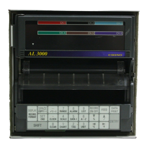
3.NAMES OF COMPONENT PARTS 3.1 Front Panel All operations of this instrument including the installation of ribbon cassette can be done from the front. Door Display board Chart cassette Keyboard Caution How to handle the door The front face of the door is made of glass. Don't give any shock to the glass face nor give any strong force to the frame for preventing an injury due to the breakage. -
Page 15: Display Board
3.2 Display Board 1) Channel No. 2) Measured value (clock) 3) Status 4) Bargraph 1) Channel No. Channel number of [bargraph]. Display depends upon the operation screens. [Multi-point sequential bargraph display] [One-point continuous bargraph display] <Digital printing in progress> ... -
Page 16: Connections
4. CONNECTIONS 4.1 Terminal Board Diagram The terminal board shown in the following figure is for the instrument with options ( alarm output + remote contacts and communications interface ) are mounted. Power/protective conductor Communications terminals (Caution) terminals (M4) *(M3.5) (option) * For the connections of Alarm output terminals illustrated are MOS relay... -
Page 17: Cautions On Connections
4.2 Cautions on Connections Observe the following cautions during connections for securing safety and reliability. 1.Feed source power supply 3. Separate the thermocouple input terminals from a heat source Use a single-phase power supply having a For thermocouple inputs, separate the input stable voltage without any waveform distortion terminals from a heat source (a heating body) for a for the purpose of preventing wrong operations. -
Page 18: Power And Protective Conductor Terminals
4.3 Power and Protective Conductor Terminals 1. Power terminals and protective conductor terminal Protective conductor terminal Power terminals 100-240V AC 50/60Hz 45VA MAX Warning Turn off the feed source power supply Turn off the feed source power supply without fail Power supply (voltage, frequency, power consumption) before connecting the power terminals and protective... -
Page 19: Measuring Input Terminals
4.4 Measuring Input Terminals 3. Connections of 1. Measuring input terminals thermocouple inputs Turn off the feed power source for preventing an Use a thermocouple wire (or extension wire) to electric shock accident. the input terminals of this instrument without 1) Measuring input terminals are provided at the fail. -
Page 20: Alarm Output Terminals (Option)
4.5 Alarm Output Terminals The following connections apply to the instrument with an alarm output function (option) only. There are three kinds of alarm outputs available: (1) MOS relay 'c' contact output, (2) mechanical relay 'c' contact and (3) mechanical relay 'a' contact output, which are shipped by the designated outputs. The mechanical relay 'c' contact output does not conform to the international safety standards. - Page 21 3. Cautions on connections Be careful with the following remarks and references on connections. Remarks 1 Reference 1 Selection of buffer relay Contact rating of MOS relay output Maximum voltage----240V (AC, DC) 1) Coil rating-------Less than the contact rating Maximum current----50mA (AC, DC) * of output terminals *Irrespective of load types 2) Contact rating--More than twice the load...
-
Page 22: Remote Contacts Terminals (Option)
4.6. Remote Contact Terminals The following connections apply to the instrument having the remote contacts function (option) only. For the remote contacts, refer to par. 13. 1. Remote contacts terminals Terminal functions Terminal names Functions 1) Printing ON/OFF EX1 and EX2 2) Selection of 3 chart Remote speeds... -
Page 23: Communications Terminals
4.7. Communications terminals These terminals are for the communications interface (option). For details of the connection, refer to the instruction manual for the "Communications Interfaces" provided separately. 1. Communications terminals RS-232C Terminals RS-422A Terminals RS-485 Terminals SDA SDB RDA RDB SG 2. - Page 24 3. RS-422A, RS-485 Connections RS-422/485 communications interface is connected to a personal computer via a line converter (our Model SC8-10: sold separately). Three signals of SD, RD and SG are used between the line converter and the personal computer but any control signal is not used. Wiring processing for control signal in a connector is necessary in the same as 2.RS-232C connections.
- Page 25 MEMO...
-
Page 26: Installation
5. INSTALLATION 5.1. Chart Loading 1. Chart cassette removal 2. Chart loading 1) Open the door. 1) Open the front and rear chart holders. Door Stripper plate Chart guide Keyboard 2) Prepare a chart. Shuffle both ends of the chart for preventing 2) Tilt the keyboard this side. - Page 27 3. Sprocket 4. Check Draw out the chart about 20cm and close the 1) Manual check ○ rear stripper plate. Turn the thumb wheel by hand to make sure that Fit the holes in chart over sprockets at both the chart is feeding properly. ○...
-
Page 28: Cassette Ribbon Installation
5.2. Cassette Ribbon Installation 1. Preparation 1) Move the printer to the center. 2) Insertion of cassette ribbon Turn on the power supply. ○ Cassette ribbon After initial operation, measured values are ○ displayed. When the RECORD ON does not illuminate, it ○... - Page 29 3. Replacement Remarks Winding knob direction Don't turn this knob clockwise, otherwise a 1) Preparation ink ribbon winding failure occurs. Move the printer to the center referring to 1.-1) ○ on the last page. Prepare a new cassette ribbon. ○ 2) Open the display board.
-
Page 30: Basic Operation
6. BASIC OPERATION 6.1. Turning On and Off the Power Supply and Operation Power switch is to prepared externally 1. Turning on and off the power supply Power and protective This instrument is not provided with any power conductor terminals switch. -
Page 31: Turning On And Off The Printing Operation
6.2. Turning On and Off the Printing Operation 1. Turning on and off the printing Printing is turned on and off selectively each time Status display when printing is turned on keys are pressed. RECORD ON illuminates. RECORD ON illuminates. Print ON Remarks 1 RECORD ON disappears. -
Page 32: Fast Feed Of Chart/Time Line
6.3. Fast Feed of Chart/Time Line 1. Fast feed of chart 2. Time line setting method The chart is fed at a rate of about 10mm/sec when The time line is printed at fixed-time intervals. By setting the time line to the time scale lines of the key is being pressed. -
Page 33: Selection Of Operation Screens
6.4. Selection of Operation Screen Three operation screens are switched from each other by pressing key once. [Multi-point sequential display] Measured Measured values in CH1 to Channel No. value CH6 (Measured values are display updated in about 5 seconds.) Multipoint sequential display Bargraph (Channels are advanced at display... - Page 34 7. PROGRAMMING 7.1. Necessity of Programming and Parameters/Functions Major default parameters 1. Necessity of programming Parameters Defaults Range No. 07(-5.00 to +5.00V) Various programming parameters Range/ ○ printing range Printing range 0.00 to 5.00(V) prepared to be able to apply this instrument to °C/°F operation selection °C versatile uses.
-
Page 35: Programming
7.2. Default Parameters/Functions and Programming Ranges 1.Parameters to be programmed before operation Programming Parameters Defaults Programming ranges Entry (Note) items 01 to 10 (Voltage), 21 to 56 (Thermocouple), 07 (±5V) Range No. Range/ 70 to 80 (Resistance thermometer) printing RJ enabled/ 0 (Disabled), 0 (Disabled) range... - Page 36 Programming Parameters Defaults Programming ranges Entry (Note) items Absolute Max. 5 digits including value signs Max. 5 digits without sign. Rate-of- Program a change value Alarms Alarm change per [measuring intervals x 1.Absolute value value measuring count]. alarm Max. 5 digits without sign. 2.Rate-of- Not programmed Program a difference...
- Page 37 Parameters Programming items Defaults Programming ranges Entry (Note) Select Ar out of Sd (standard), Format selection Ar ,SP, and PL 1 to n, Channel n: Number of channels = 6 Automatic a (Lower-limit value≦a<b) Zero of No.1 range range Span of No. 1 range b(a<b<c) -shift(Ar) (Max.
-
Page 38: Key Functions
7.3. Programming Keys and Key Operations 1. Keyboard Lower display functions are operated when pressing these keys together with key. (Certain keys must be pressed for longer than 3 seconds.) 1. Key operations Press for longer than 3 seconds together with Press independently Press together with [SHIFT] key [SHIFT] key... - Page 39 2) Keys to be pressed together with shift key Keys Names Functions The [printing format (option)] programming mode appears. Decimal point appears at the selected mode out of four printing [Printing modes*. format] *4 kinds of Sd (standard), Ar (automatic range-shift), SP (compressed/expanded) and PL (zone) The copy mode to copy the same programming parameters to other Copy...
-
Page 40: Programming Procedures
7.4. Programming Procedures This paragraph shows the basic programming parameters. 1. Basis of programming flow chart Programming is interrupted to return to the Operation screen operation screen from every programming stage (Measured value or time display) by pressing [Display] key before [Entryl. Keys depend upon programming parameters. -
Page 41: Programming Error And Remedial Measures
7.5. Programming Errors and Remedial Measures The instrument judges if a programmed parameter is free of an error when pressing key in the [storing] or [temporary storing] procedure. 1. Error judgment flow chart Same programming Programming parameters parameters to other for each channel channels For programming condition... -
Page 42: Basic Programming (See Caution)
8. BASIC PROGRAMMING 8.1. Parameters to be Programmed Before Operation Certain parameters are to be programmed for starting operation after turning on the power supply. 1. Turning on the power supply Default parameters By turning on the power supply for the first time, the display and Range/printing range 07 (±5V) /0.00 to 5.00 (V) printing operation are started... - Page 43 8.2. Range/Printing Range Program the following parameters before operation. By pressing keys under the operation screen, the [range/printing range] programming display appears. Program these parameters for each channel. Character indicator 1. Programming mode and parameters Programming lamp R represents range 1) Programming mode ...
- Page 44 3. Programming flow chart <Example> Range number of channel 3 is 22, the reference junction compensation function (RJ) is used, and the printing range is set to -50 to +450°C , for example. Operation screen Channel 1 range. Other channels can be checked by keys.
- Page 45 4. Range No. Tables 1) Voltage input Input Measuring range No. Input type Measuring range Remarks type °C ゜ F -13.80 to 13.80mV WRe5-W to 2315 to 4200 -27.60 to 27.60mV Re26 -69.00 to 69.00mV PtRh40- (mV) 0 to 1888 32 to 3400 PtRh20 -200.0 to 200.0mV...
- Page 46 Operation Selection 8.3. °C/°F This program is to select [°C] or [°F] operation for the use of temperature range (thermocouple or resistance thermometer). The default is [°C] operation. By pressing keys for longer than 3 seconds from operation screen, the [°C/°F operation] selection display appears.
-
Page 47: Chart Speed
Chart Speed 8.4. Program the chart speed before operation. Default speed and programming range ・By pressing keys in the operation Default :0020 (mm/h) screen, the [chart speed] programming display Programming range :0001 to 1500 (mm/h) appears. ・For remote contacts (option), refer to par. 13.2. Character indicator 1. -
Page 48: Printings
9. PRINTINGS 9.1. Printings Printing comprises trace printing and digital printing. Trace printing, channel number printing, and fixed-time printing are carried out even if no programming is done. Printings Printing contents Remarks Trace printing is executed by dot-printing by colors every channel. -
Page 49: Digital Data Printing
9.2. Digital Data Printing Measured values are digitally printed at the requested time, but trace printing is interrupted. Remarks 2 Press keys. ○ Trace printing (dot-printing) is interrupted and the chart is fed a little. Operation screen ○ The measured values at the time pressing keys are printed. ○... -
Page 50: List Printing
9.3. List Printing Press keys. Programmed parameters [range/printing ○ range], [scale], [chart speed], etc. can be printed, Trace printing is interrupted. Chart is fed but trace printing is interrupted. slightly and list printing is started. After the end, the chart is fed a little, and the ○... -
Page 51: Programming Printing Formats
9.4. Programming Printing Formats This programming is for the instrument with a printing format function (option) only. Trace printing formats can be selected. Kinds of format and programming Kinds Programming 1. Kinds of printing formats Standard() Not required ○ Select a desired format in advance. The default Automatic range-shift() Par. -
Page 52: Operations
10. OPERATIONS 10.1. Fixed-Time Printing Intervals Fixed-time printing is started after turning on the power supply. The following table shows an outline of the intervals according to the printing contents. Time and time line Channel number Chart speed Scale, tag, engineering unit In the order of channel In the order of channel Depends upon chart... -
Page 53: Restrictions Of Printings
10.2. Restrictions of Printings 1. Stop of digital printing due to chart speed If the chart speed is programmed to be faster than 251mm/h, none of digital printing is executed, but trace printing only is done. (The time line printing, digital data printing, and list printing can be executed.) 2. -
Page 54: Operations At Abnormal Inputs
10.3. Operations at Abnormal Inputs 1. Over-range input Definition of Input The operation differs according to whether the input Measuring range is out of the printing range being programmed by [range / printing range] or out of the measuring Printing range range determined by range number. -
Page 55: Alarm Display And Printings
10.4. Alarm Display and Printings Alarms are activated by programming [Alarms]. (par. 11.5). 1. Alarm displays The alarm-on status and channels are indicated in all operation screens. Multi-point sequential or one-point continuous display Clock display S t a t u s : ALARM illuminates S t a t u s : ALARM illuminates Channel : Measured value of alarm-on channels Channel : Alarm-on channel numbers are... -
Page 56: Other Programmable Parameters/Functions
11. OTHER PROGRAMMABLE PARAMETERS/FUNCTIONS 11.1 Other Programmable Parameters/Functions 1. Various functions [An example of printings on chart during operation] 1:TIC10 °C 1200 Scale Scale 08:30 3:15.9KG 1:1010℃ 2:950.0℃ Periodic 5: 650℃ 6:13.5PP 4: 550℃ Engineering data printing unit 08:00 10:45 2L2 20MM/H Alarm [Lower part of display]…..Screen switched to [Time display and others]... - Page 57 11.2. Scale [Scale] programming is necessary when a voltage input from a converter, etc. is displayed on an actual scale. However, the scale is programmed with the same characteristic scale (not linearized scale) as voltage input. This programming is also necessary when the decimal point position is changed in thermocouple or resistance thermometer input channels.
-
Page 58: Scale
4. Programming display Scale Unused digits are Display (max. 11 digits by left-justify) filled with spaces character Cursor Channel Lower-limit value Higher-limit value (Within 5 digits) (within 5 digits) Scale value to print 0% Scale value to print 100% For programming the Remarks... -
Page 59: Skip (Channel Deletion) Function
11.3. Skip (Channel Deletion) Function When clearance (non-programming condition) is stored in range programming, printing and display can be skipped. By pressing keys in operation screen, the [range/printing range] programming display appears. No skip function is programmed to all channels as the default function. Operation of skipped channels 1. - Page 60 3. Programming flow chart for reprogramming to no-skipped status <Example> Reprogram channel 3 to no-skipped condition and program the range to K thermocouple 0 to 1200 °C Other programming parameters Operation screen Programmed parameters [scale], [engineering unit], [tag], and [alarms] are cleared in the skipped channels.
-
Page 61: Subtract Printing Function
11.4. Subtract Printing Function This programminq is for printing a difference between channels or between a channel and the reference value. By pressing keys, the [range/printing range] programming display appears and this mode is transferred to the programming [subtract printing]. 1. - Page 62 3. Programming flow chart <Example> Printing of ( channel 1 - channel 2 ) within a printing range of ±250 in channel 3. Reference Subtract printing Subtraction channel channel channel Operation screen Reference 1 Other channels check Channels are changed by pressing [Check] key.
-
Page 63: Alarm Parameters
11.5. Programming Alarms Alarm parameters (alarm types, alarm value, etc.) can be programmed for each alarm point (channel, level). By programming alarm parameters, display of alarm-on and printings of alarm-on/reset can be executed. The [alarm parameters] programming display appears by pressing keys. - Page 64 3. Programming mode 1) Absolute value alarms () ; Channel Alarm value (Note) Display Alarm type Output Max. 5 digits by left-justify character Level number* Cursor Unused digits are filled with a space. (Note) Program alarm values within the scale range.
- Page 65 4. Programming flow chart Deleting an alarm point Display an alarm point by Operation screen keys according to the "programming alarm point" procedure, clear it by pressing keys, and then, + [Check] perform [temporary storing] [storing] operation. Reference 1 [For programming Remarks...
-
Page 66: Programming Alarm Dead Band
11.6. Programming Alarm Dead Band Dead band can be programmed between alarm-on and alarm-reset. By pressing keys for longer than 3 seconds, the [alarm dead band] programming display appears. This programming is common to all alarm points. Alarm dead band 1. -
Page 67: Periodic Data Printing Function
11.7. Periodic Data Printing Function This programming is for digital printing (data printing) at fixed intervals. Printing overlaps with trace printing (dot-printing). By pressing keys, the [periodic data printing] programming display appears. Since the default parameter of periodic data printing is "not programmed"... -
Page 68: Time
11.8. Time Year, month, day, and time can be programmed. By pressing keys, the [time] programming display appears. The default time is Japanese time. 1. Programming mode Hour Minute Month... -
Page 69: Engineering Units
11.9. Engineering Units An engineering unit of max. 5 digits can be assigned for digital printing, scale printing, and list printing. By pressing keys, the [engineering unit] programming display appears. An example of unit printing (Digital data printing) (Scale printing) (List printing) 1. - Page 70 3. Programming flow chart For programming the Remarks engineering unit to be "none" <Example> Programming the engineering unit of channel Select the channel where the ○ 3 from PPM to G/MIN engineering unit is set to be "none" by Operation screen key.
-
Page 71: Tags
11.10 Tags A tag (TAG) of max. 9 digits can be assigned for channel printings (scale, list). The [TAG] programming display appears by pressing keys. As the default parameter is "not programmed", no character appears. Tag printing example (Scale printing) (List printing) 1. - Page 72 2. Programming flow chart <Example> No tag to TIC- 10 in channel 3 For programming the tag Remarks printing to be "none" Operation screen Select the channel where the tag is ○ programmed to be "none" by [Check] key. * ...
-
Page 73: Burnout Function
11.11. Burnout Function The channel where the temperature range has been programmed becomes effective. By pressing keys for longer than 3 seconds in operation for each screen, the [burnout enabled/disabled] programming display appears. Perform this programming for each channel. 1. Burnout Burnout selection menu Burnout can be selected for each channel out of 3 kinds ・If a sensor (thermocouple or resistance... -
Page 74: Passcode/Key Lock
11.12. Passcode/Key Lock [Key lock] selection procedure differs according to [passcode programmed or not programmed]. By pressing keys for longer than 3 seconds in the operation screen, [passcode programmed/ not programmed] check display appears. If the passcode has been programmed, [key lock] selection display will not be accessible without the correct passcode. - Page 75 4. When passcode is not programmed; (Example) Program the passcode and program the key lock to be effective. Longer Passcode programmed/ than Reference 1 Operation screen not programmed 3sec. : Indicates that no passcode is [Passcode programmed/ Longer programmed. not programmed] than 3sec.
- Page 76 5. When the passcode is programmed; <Example> Program the key lock to be effective when the passcode is changed or not changed. Selecting key lock to be Operation screen Reference 1 ineffective or effective By pressing key, the key lock is selected to be effective or ineffective.
- Page 77 11.13. Copying Function For the [range /printing range], [scale], [engineering unit], and [tag] to be programmed for each channel, programmed values of an optional reference channel can be copied to other channels. 1. Programming mode…… Character display An example of programming the [range/printing range] is shown below. Programming lamp Programming ...
-
Page 78: Alarm Output
12. ALARM OUTPUT Alarm output is an option. Program [output number] on every alarm point in the [programming alarm output number] of [alarms] programming. 1. Alarm output Arrangement of alarm output terminals When alarm is on, the terminals of N.O and COM MOS relay Mechanical of alarm output terminals (output number) -
Page 79: Remote Contacts
13. REMOTE CONTACTS 13.1. Remote Contacts Functions This function applies to the instrument with a remote contacts function (option) only. Remote contacts terminals 1. Remote contacts The following operation can be done with contact signals of remote contacts terminals. 1) Printing ON/OFF Remote Printing can be turned ON and OFF without contacts... -
Page 80: Remote Contacts Function
13.2. Programming 3 Chart Speeds 3 chart speeds programming display appears at optional remote contacts only. By pressing keys, the [3 chart speeds] programming display appears. After programming 3 kinds of speed (CS1 to 3), select them with a contact signal. 1. -
Page 81: Printing Format
14. PRINTING FORMAT 14.1. Programming Automatic RangeShift Printing Programming display appears at optional printing format only. This programming is to change trace printing range automatically. A programming example of automatic range-shift <In case of range No. 23 (K thermocouple)> 1. Automatic range-shift Measuring range -200 1370... - Page 82 3. Programming flow chart <Example> Programming channel 6 to the example on the left page Remedial measure Remarks 1 to error display Operation screen Press a key other than key and reset. Display transfers to the next one, + if normal. [Printing format check] ...
- Page 83 14.2. Programming Compressed and Expanded Printing A programming example of Programming display appears at optional compressed and expanded printing. printing format only. This programming is <In case of range No. 23 (K thermocouple)> to print compressed or expanded partially. Measuring range 1.
- Page 84 3. Programming flow chart <Example> Programming channel 6 to the example on the left page Remedial measure Remarks 1 to error display Operation screen Press a key other than key and reset. Display transfers to the next one, if normal. [Printing format check] ...
-
Page 85: Programming Zone Printing
14.3. Programming Zone Printing Programming display appears at optional printing format only. This programming is to divide trace printing into 2 zones. A programming example of zone printing 1. Zone printing <Channel 1,3,5 No. 1 zone Channel 2,4,6 No.2 zone> The trace printing is divided into two zones Channel Channel... - Page 86 3. Programming flow chart <Example> Programming to the example on the left page Remedial measure Remarks 1 to error display Operation screen Press a key other than key and reset. Display transfers to the next one, if + normal. [Printing format check] ...
-
Page 87: Other Options
15. OTHER OPTIONS 15.1. High-Speed Trace Printing Selecting display appears at optional high-speed trace printing only. The trace printing interval can be selected out of about 5 sec. (standard trace printing) or about 2.5 sec. (high-speed trace printing). Renewal intervals of various displays Printing intervals of high-speed trace printing High-speed Standard... -
Page 88: Shunt Resistors For Current Input
15.2. Shunt Resistor for Current Input A DC current input can be measured by connecting a shunt resistor (option) to the input terminals and converting the current input into a voltage level. 1. Shunt resistor (option) and Shunt resistor and measuring range measuring current range Resistance Code... -
Page 89: Mathematical Function And Totaliser
15.3. Mathematical Function and Totaliser 1. Option of mathematical functions Mathematical functions is to carry out mathematical functions to measured data, and to display and to ○ record the result. There are 11 kinds of mathematical functions as shown in the following table, which can be selected to ○... -
Page 90: Adjustments
16. ADJUSTMENT 16.1. Adjustment of Measuring Values Kinds of adjustment Adjustment comprises three kinds shown below. ○ and ○ have been already adjusted. However, it is recommended for maintaining the measuring and printing accuracy to adjust them once every year. Calibration Contents Method... - Page 91 3. Connections Connections depend upon the input types. Connect a standard tool and other tools to the measuring input terminals to be adjusted. Caution Turn off the source power supply before starting connections Turn off the source power supply before starting connections for the purpose of preventing an electric shock accident.
- Page 92 4. Programming flow chart <Example> Adjustment of channel 1 (printing range -50 to + 150) Longer Operation screen than For returning to operation Remarks 1 2sec. screen Remarks 1 Calculated correction data are canceled Longer by returning to the operation display at than 3sec.
- Page 93 16.2. Shift Programming of Measured Values This programming is executed when it is desired to change a measured value slightly and the subsequent measured values become the shifted values. 1. Shift programming An example of shift programming This programming is executed for each channel. ○...
-
Page 94: Zero And Span Adjustment
16.3. Adjustment of Trace Printing Position Zero and span adjustment at trace printing position can be done. It is recommended for maintaining the printing accuracy to adjust the trace printing position once every year. 1. Zero and span adjustment Adjustment can be done by pressing [ENTRY] key at the position where the trace-printing position has been met. -
Page 95: Hardware Checks
17. HARDWARE CHECK 17.1. ROM Version Check Kinds of hardware check Hardware check comprises the following six kinds. Items ○ and ○ apply to the instrument with the alarm output plus remote contacts (option) functions. Check name Contents Methods ROM version check ROM version can be confirmed. -
Page 96: Printer Test
17.2. Printer Test The printer can be tested. 1. Test Printing Trace printing Purple Brown Green Digital printing Blue Black 2. Test flow chart Test printing contents 1. Digital printing Operation screen Longer ・40 characters (repetition of A to Z, 1 to (Note) than 9,0) are printed on one line. -
Page 97: Display Test
17.3. Display Test The display can be tested by sequentially lighting 16 and 7- segment LCDs, bargraph, and lamps. 1. Display board 16-segment LCD 7-segment LCD Status lamp Bargraph 2. Test flow chart Operation screen Longer Lighting sequence than 2sec 1. -
Page 98: Alarm Output Check (Option)
17.4. Alarm Output Check This check applies to the instrument with an alarm output function (option) only. Alarm outputs can be checked by outputting either shorted (ON) or open (OFF) signal from specified alarm output terminals. 1. Check flow chart Alarm output terminals <Example>... -
Page 99: Remote Contacts Input Check (Option)
17.5. Remote Contacts Input Check This check applies to the instrument with a remote contacts function (option) only. Input signals (shorted/ open) of remote contacts terminals can be checked. 1. Check flow chart Remote contacts terminals Operation screen Longer than 2sec Longer than 3sec... -
Page 100: Programming Initialize
18. PROGRAMMING INITIALIZE Programmed values and correction data after calibration can be initialized to the default values. 1. Kinds of initialize Kinds Initializing contents and cautions Programmed Initializes all programmed values excluding [time] to the default values. values For the default values list, see par. 7.2. Initializes all calibrated correction data to the default values. -
Page 101: Maintenance/Troubleshooting
19. MAINTENANCE/TROUBLESHOOTING 19.1. Routine Inspection Check the residual quantity of chart, printing conditions, etc., and use the instrument under a good condition at all times. 1. Consumable parts check Check items Checking methods Check the residual quantity of chart. When the residual quantity becomes less than 60 cm, a message "Prepare the new chart"... -
Page 102: Lubrication And Cleaning
19.2. Lubrication and Cleaning 1. Lubrication Lubricate the main shaft of the printer once every 6 months Turn off printing by pressing keys. (The printer stops at about the center) ○ Turn off the power supply. ○ Open the display board and remove the cassette ribbon. (See par. 5.2 3.) ○... -
Page 103: Measuring Values Check
19.3. Measuring Values Check It is recommended for maintaining the measuring accuracy rating to check measuring values once every year. 1. Channels to be checked Reference conditions during check Check measuring values for each channel. Items Reference conditions Errors may be different between channels even Ambient temperature in the same range. - Page 104 3. Connections Connections depend upon the input types. Connect a standard tool and other tools to the measuring input terminals to be adjusted. Caution Turn off the source power supply before starting connections Turn off the source power supply before starting connections for the purpose of preventing an electric shock accident.
-
Page 105: Troubleshooting
19.4. Troubleshooting Troubleshooting methods are shown by symptoms. Read corresponding symptom items. Warning Repair and modifications Never repair or modify the instrument by replacing assembled component units or parts, otherwise correct repair or modifications cannot be executed and also an electric shock accident or the damage of the instrument may occur. -
Page 106: Other Troubles
3. Displays Symptoms Causes and remedial measures Measured value flickers in an alarm-on channel. 1) Measured value flickers See par.10.4. 2) Measured value is blank Measured value is blank in the skipped channel. Decimal point lights when the operation screen is switched 3) Decimal point lights in the channel to one-point continuous bargraph displaly. -
Page 107: Recommended Parts Replacement Intervals
19.5 Recommended Parts Replacement Intervals It is recommended to replace parts periodically as preventive maintenance for using the instrument under good conditions for a long time. Warning Replacement of parts Don't replace any parts other than consumable chart and cassette ribbon, otherwise the instrument cannot be recovered correctly and a dangerous accident may also occur. -
Page 108: Specifications
20. SPECIFICATIONS 1. INPUT SPECIFICATIONS Number of measuring points: 6 points Input signals: DC voltage………………..…..±13.8mV, ±27.6mV, ±69.0mV, ±200mV, ±500mV, ±2V, ±5V, ±10V, ±20V, ±50V DC current……………...…..Available by adding shunt resistors (option) Thermocouples……………….B, R, S, K, E, J, T, N, NiMo-Ni, CR-AuFe, PtRh40-PtRh20, WRe5-WRe26, W-WRe26, PlatinelⅡ, U, L Resistance thermometer…….Pt100 (IEC751 1995), Ptl00 (IEC751 1983), JPt100, Pt50, Pt-Co Range... - Page 109 2. PRINTING SPECIFICATIONS Printing interval : About 5 seconds/point Printing dead band : AL ……0.2% Printing system : Wire-dot type 6- color ribbon on trace and digital printings Red, ○ 2 Black, ○ 3 Blue, ○ 4 Green, ○ 5 Brown, ○ 6 Purple Print/color : Trace printing (dot)…..○...
-
Page 110: General Specifications
4. ALARM SPECIFICATIONS Alarm point : Channel numbers × levels (4) Alarm types : Select from the following six types for each alarm point. Absolute value H: Higher-limit L: Lower-limit Rate-of-change *1 U: Increase-limit d: Decrease-limit Differential *2 b: Differential higher-limit S: Differential lower-limit *1: Variation range per unit time (Note) (Note) Measuring cycle ×... - Page 111 Dielectric strength: Primary and protective conductor terminals ..........1 minute at 1500VAC Secondary and protective conductor terminals..........1 minute at 500 VAC Primary and secondary terminals ..............1 minute at 2300VAC Alarm terminals (Mechanical relay) and other secondary terminals..1 minute at 1000VAC (Note) Primary terminals : Power terminals (L,N), Alarm output terminals (MOS relay) Secondary terminals : Measuring input terminals, Remote contacts terminals,...
- Page 112 6. Accuracy Ratings Input Reference Accuracy Reference Accuracy Measuring range No. Input type Measuring range type range rating range rating -13.80 to 13.80mV WRe5 ±13.8mV 0 to 2315 °C ±69.0mV -27.60 to 27.60mV -WRe26 ±27.6mV DC PtRh40 -69.00 to 69.00mV ±69.0mV (mV) 0 to 1888 °C ±13.8mV...
- Page 113 7. Option specifications Options Explanations About 1 sec/6-point. Conforms to CE marking indications equivalent to max. Measuring interval or 2mV may fluctuate in the test environment demanded by EMC °C command. By using 4-point contact inputs, the following operation is executed. Remote contacts Selection of 3-chart-speed/printing off, digital data printing, list printing Alarm point : 6-point (OR output possible)
- Page 114 MEMO...
- Page 116 32-8, KUMANO-CHO, ITABASHI-KU, TOKYO 173-8632 Telephone : 81-3-3956-2171 Facsimile : 81-3-3956-0915 Printed in Japan (...
Need help?
Do you have a question about the AL3000 SERIES and is the answer not in the manual?
Questions and answers