Table of Contents
Advertisement
Quick Links
Advertisement
Table of Contents

Related Manuals for Compact Electric CDMR-51


Summary of Contents for Compact Electric CDMR-51
- Page 1 DIGITAL LINE MONITORING RELAY CDMR-51 1 1 0 0 V i e n n a , D O E R E N K A M P G A S S E 7 TEL.: + 43 / 1 / 815-12-71-0 or + 43 / 1 / 815-51-74-0 FAX.: + 43 / 1 / 813-64-21-21...
-
Page 2: Table Of Contents
Line Monitoring Relay CDMR-51 / User Manual Page 2 Index: Spezifications ….. ………………………..……………………… Page 3 Terminal and wiring diagram (Abb.1) …………………………. Page 4 Configuring the relay …………….……………………………. Page 5-6 Change of setting values ……………………………………… Page 6 Assignment of output relays to individual monitoring functions and negation of output relays …………. -
Page 3: Spezifications
Line Monitoring Relay CDMR-51 / User Manual Page 3 Specifications (other specifications on request) Line Voltage Inputs: Rated voltage U ....a) 3x 400V/230VAC b) 3x 100-110V / 58-64VAC Measuring range ...... : 1,3 Un Overload capability ....2 Un (100% duty cycle) Input resistance .... -
Page 4: Terminal And Wiring Diagram (Abb.1)
Line Monitoring Relay CDMR-51 / User Manual Page 4 Fig. 1: Terminals and WIRING DIAGRAM CDMR-51 Line Voltage U Serial Interface Supply. U AC: (P) DC: ( ) Star-type system (4-wire mains) connecting diagram Delta system (3-wire mains) connecting diagram... -
Page 5: Configuring The Relay
Line Monitoring Relay CDMR-51 / User Manual Page 5 Introduction: The CDMR-51 is a digital line monitoring relay based on a new generation microcontroller. It provides 13 monitoring functions listed below with identification symbols. U< ... undervoltage stage 1 f< ... underfrequency stage 1 PS>... -
Page 6: Change Of Setting Values
Line Monitoring Relay CDMR-51 / User Manual Page 6 Attention: Operating in parallel with system requires undervoltage limits >= 70% Un (rated voltage) of at least one undervoltage function, because frequency and phase shift functions are inhibited, if all 3 voltages drop below 70% of Un. -
Page 7: Assignment Of Output Relays To Individual Monitoring Functions And Negation Of Output Relays
KU Detection (only for 230/400 V Relays-Type) In case of tripping of the CDMR-51 and the mains is in order within 3 seconds, then the generating plant is reconnected within 5 seconds. (Instead of the time, which is preset as Lock-out Time.). If this parameter is off, the KU detection is inactive. -
Page 8: Functional Diagram, Security Code
Line Monitoring Relay CDMR-51 / User Manual Page 8 If the Parameter „fU Connect-Logic“ is turned off, the settings U> / U< und f> are taken as tripping values also after the connection. Functional diagram for activated setting of: - Lock-out Time... -
Page 9: External Blocking Input "B
Line Monitoring Relay CDMR-51 / User Manual Page 9 Ba>: unbalance voltage f<<, f<, f>, f>>: line frequency PS>: phase shift values in L1, L2 and L3 Note: If the line voltage is used as supply voltage a correct storage of these data cannot be guaranteed in case of total line drop out. -
Page 10: Serial Interface
Line Monitoring Relay CDMR-51 / User Manual Page 10 Serial Interface: The serial interface provides an easy tool to configure the relay via Laptop or PC and to save parameter settings on disc or make a hardcopy for documentation. A special adapter to a standard 9 pin SubD COM connector is available. - Page 11 Line Monitoring Relay CDMR-51 / User Manual Page 11 Displaying measuring values on the screen: Select the menue "Information”. The window shows the relay ID, the line values and the state of K1 .. K5. All values are refreshed in 1s interval.
-
Page 12: Menue-Diagram (Abb.5)
Line Monitoring Relay CDMR-51 / User Manual Page 12 Fig. 5.: CDMR-51 MENUE DIAGRAM Return to this menue from any menue by pressing the keys simultaneously Line Y/Y 50.00Hz Line Y/ 50.00Hz Line measuring values: 230V 230V 230V 400V 400V 400V... -
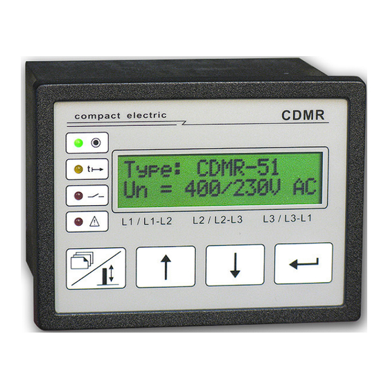
Page 13: Front-Display And Keypad (Abb.6)
Line Monitoring Relay CDMR-51 / User Manual Page 13 Fig. 6: FRONT- DISPLAY AND KEYPAD Mains 1) Standard-Display: configuration = star-type Menue ID. = delta LINE MEASURING VALUES measuring If any tripping is active values the tripping function- = star voltage... -
Page 14: Parameterlist And Settings (Tab.1)
Line Monitoring Relay CDMR-51 / User Manual Page 14 Table 1: Type: CDMR- 51 Serial-No: U(rated): ... V AC Plant: Cubicle: Date: Factory Factory Param Setting Customers Funct. Parameter Setting Setting No. *) Range Setting Value 230 / 400 V... - Page 15 Line Monitoring Relay CDMR-51 / User Manual Page 15 Factory Factory Param Setting Customers Funct. Parameter Setting Setting No. *) Range Setting Value 230 / 400 V 57 / 100 V Setting Value f< [45 -65] Hz 47,50 Hz 49,80 Hz Trip Delay f<...
Need help?
Do you have a question about the CDMR-51 and is the answer not in the manual?
Questions and answers