Table of Contents
Advertisement
Quick Links
D I G I TA L L I N E M O N I TO R I N G R E L AY
Specifications ..................................................... 2-3
Terminals and Wiring-Diagram (Fig.1) ............... 3
Change of setting values ................................... 6
Assignment and negation of output relays ......... 6
Security code ..................................................... 6
Realtime clock.................................................... 7
CDMR-61
User Manual
Event history buffer..................................................
Self-monitoring .........................................................
4-5
Serial interface .........................................................
Menue diagram (Fig.3) ............................................ 10
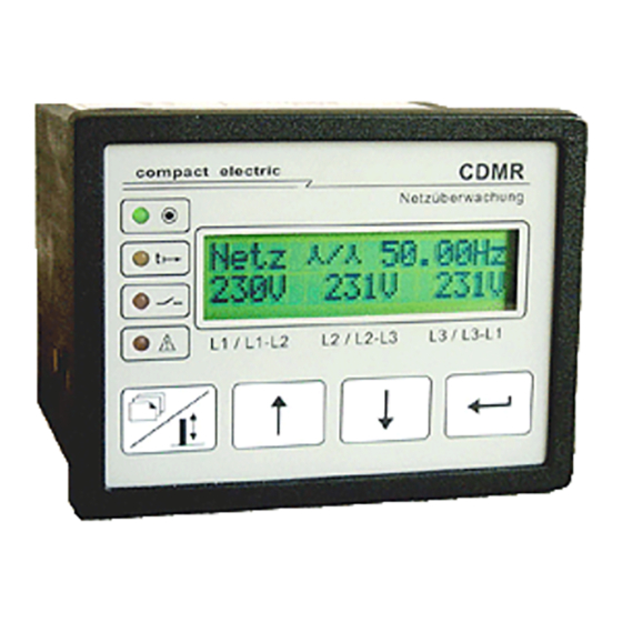
Front panel (Fig.4) ................................................... 11
Table 1: Parameter listing (including setting
ranges and values) .............................................. 12-13
1 1 0 0 W i e n , D O E R E N K A M P G A S S E 7
TEL.: + 43 / 1 / 815-12-71-0 od. ++ 43 / 1 / 815-51-74-0
FAX.: + 43 / 1 / 813-64-21-21
h t t p : / / w w w . c o mp a c t e l e c t r i c . a t
h o m e p a g e :
7
7
8
8
Advertisement
Table of Contents

Related Manuals for Compact Electric CDMR-61


Summary of Contents for Compact Electric CDMR-61
-
Page 1: Table Of Contents
User Manual Specifications ............. 2-3 Event history buffer..........Terminals and Wiring-Diagram (Fig.1) ....3 External blocking input "B" ........Configuration of the CDMR-61 and Self-monitoring ............information about monitoring function details ..Serial interface ............Change of setting values ........6 Menue diagram (Fig.3) .......... -
Page 2: Specifications
Line Monitoring Relay CDMR-61 / User Manual Page 2 Specifications (other specifications on request) Line Voltage Inputs: Rated voltage U ....a) 3x 400V/230VAC b) 3x 100-110V / 58-64VAC Measuring range ...... : 1,3 Un Overload capability ....2 Un (100% duty cycle) Input resistance .... -
Page 3: Terminals And Wiring-Diagram (Fig.1)
Line Monitoring Relay CDMR-61 / User Manual Page 3 Fig.1 Terminals and Wiring Diagram CDMR-61 Line Voltage U Serial Interface Supply. U AC: (P) DC: ( ) Star-type system (4-wire mains) connecting diagram Delta system (3-wire mains) connecting diagram L1 L2 L3 N... -
Page 4: Configuration Of The Cdmr-61 And Information About Monitoring Function Details
Line Monitoring Relay CDMR-61 / User Manual Page 4 Introduction: The CDMR-61 is a digital line monitoring relay based on a new generation microcontroller. It provides 13 monitoring functions listed below with identification symbols. U< ... undervoltage stage 1 f< ... - Page 5 Line Monitoring Relay CDMR-61 / User Manual Page 5 Attention: Operating in parallel with system requires undervoltage limits >= 70% Un (rated voltage) of at least one undervoltage function, because frequency and vector surge functions are inhibited, if all 3 voltages drop below 70% of Un.
-
Page 6: Change Of Setting Values
Line Monitoring Relay CDMR-61 / User Manual Page 6 Refer to fig.3 and fig.4 for additional information. 1. Starting from the standard line measuring values menue step through the main-menue Undervoltage U< level with the keys ↓ ↑ to the main menue of the desired function (e.g. U<). -
Page 7: Realtime Clock
Realtime clock The CDMR-61 is equipped with a realtime clock with a supply-buffer of 60 hours minimum. The time resolution is 1s. Date and time of the internal clock are displayed in a menue of the "General Settings" menue chain. The clock settings may be changed in this menue as well as by the PC program. -
Page 8: Self-Monitoring
Line Monitoring Relay CDMR-61 / User Manual Page 8 2 .... Blocking of all 13 monitoring functions. If blocking is released and a line fault present, tripping is performed after the time delay programmed for the corresponding monitoring function. Self-monitoring... - Page 9 Line Monitoring Relay CDMR-61 / User Manual Page 9 or b) from a file „Datei“ / „öffnen“ (File-Extender: ".par") 2. Enter the parameter setting values and send to the relay ( “Relais” / “Parameter senden“) Data transfer does not disturb relay operation with one exception: If the configuration star-type / delta mains is changed a short undervoltage tripping may occur.
-
Page 10: Menue Diagram (Fig.3)
Line Monitoring Relay CDMR-61 / User Manual Page 10 Fig. 3: CDMR-61 MENUE-DIAGRAM file: menue1e.cdr CDMR61e_man_A1.doc... -
Page 11: Front Panel (Fig.4)
Line Monitoring Relay CDMR-61 / User Manual Page 11 CDMR61e_man_A1.doc... - Page 12 Line Monitoring Relay CDMR-61 / User Manual Page 12 Tab.1: Type: CDMR-61 Serial-Nr: U(rated): ... V AC Plant: Cubicle: Date: Note: The voltage setting ranges and values are listed below in % of the rated voltage. The CDMR displays these values in [Volt].
- Page 13 Line Monitoring Relay CDMR-61 / User Manual Page 13 Par. Setting Default Customers Funct. Parameter range setting setting value f< Trip Frequ [45 -65] Hz 49.80 Hz f< Trip Delay [0.06 - 60] s 0.12s f< Return Delay [0.06 - 60] s 0.12s...
Need help?
Do you have a question about the CDMR-61 and is the answer not in the manual?
Questions and answers