ACU-RITE 300S Reference Manual
Readout
Hide thumbs
Also See for 300S:
- Step-by-step instructions (16 pages) ,
- Step-by-step instructions (16 pages)

Subscribe to Our Youtube Channel
Related Manuals for ACU-RITE 300S

Summary of Contents for ACU-RITE 300S
- Page 1 300S R EADOUTS REFERENCE MANUAL SALES & SERVICE: A Tech Authority, Inc. 13745 Stockton Ave. Chino CA 91710 909-614-4522 sales@atechauthority.com...
-
Page 3: 300S Soft Keys
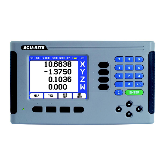
300S Key Layout Display Area Soft keys Power Indicator light Arrow Keys: Use the UP/DOWN keys to adjust the screen contrast. Axis Keys Numeric Keypad ENTER key CLEAR key 300S Soft keys There are multiple pages of soft key functions to select from the operating modes. - Page 4 Soft Key function (Page 2a) Soft key Press to select the Circle Pattern, Linear Pattern, page 38 Incline Mill, or Arc Mill table ( This soft key toggles between radius and diameter displays. This function is for Turning applications only page 56 Soft Key function (Page 2b) Soft key...
-
Page 5: Readout Parameter Access Code
The readout is now ready for machine parameter setting operations. IMPORTANT! To prevent setup parameters from being changed, remove this page from the Reference Manual after initially setting up the readout system. Retain this information in a safe place for future use. 300S... -
Page 7: Introduction
300S DRO axis availability. The 300S Color DRO is available in two, three, and four axis form. The 4 axis 300S DRO is used through out this manual for illustration, and description of function keys. Symbols within Notes Every note is marked with a symbol on the left indicating to the operator the type, and/or potential severity of the note. -
Page 9: Warranty
Warranty Go to www.acu-rite.com for warranty information. 300S... - Page 10 viii...
-
Page 11: Table Of Contents
Incremental workpiece positions ................3 Zero Angle Reference Axis ..................4 Reading head position ..................... 4 Encoder Reference Marks ..................5 I - 2 General Operations for 300S Screen Layout ......................6 General Navigation....................7 General Overview ....................7 Graphic Positioning Aid ..................7 Help Screen ...................... - Page 12 Job Setup Parameters ................... 13 Units ......................... 13 Scale Factor ...................... 13 Mirror ........................ 14 Edge Finder (milling applications only) .............. 14 Diameter Axes ....................14 Measured Value Output..................15 Near Zero Warning.................... 15 Status Bar Settings ................... 15 Job Clock ......................15 Skew Compensation (Milling applications only)..........
- Page 13 Disabling Z0, and Z Coupling................58 Thread Cycle ......................59 Soft Key Functions.................... 59 Running the Thread Cycle Program ..............64 I - 5 Programming 300S Overview ....................... 66 Program Mode Soft key functions ..............67 View Soft Key ....................68 Feature Soft Key functions ................
- Page 14 Non-Linear Error Compensation ............... 83 Setup procedure for Non-linear Error ..............83 ............. 84 Starting a Non-Linear Error Compensation Table Configuring the Compensation Table ............... 85 Automatic Non Linear error compensation ............85 Backlash Compensation ..................87 Counter Settings....................87 Diagnostics ......................
- Page 15 Operating Instructions 300S...
-
Page 16: I - 1 Fundamentals Of Positioning
I - 1 Fundamentals of Positioning Datums The workpiece drawing identifies a certain point on the workpiece (example: “a corner”) as the absolute datum, and perhaps one, or more other points as relative datums. The datum setting procedure establishes these points as the origin of the absolute, or relative coordinate systems. -
Page 17: Absolute Workpiece Positions
Incremental coordinates of position 3: IX = 10 mm IY = 5 mm IZ = 20 mm If you are drilling, or milling a workpiece according to a drawing with incremental coordinates, you are moving the tool by the value of the coordinates. 300S... -
Page 18: Zero Angle Reference Axis
- 270° ... positive Y axis Reading head position The reading head position provides feed back to the 300S that converts the movement of the machine axes into electrical signals. The 300S constantly evaluates these signals, and calculates the actual positions of the machine axes, which it displays as a numerical value on the screen. -
Page 19: Encoder Reference Marks
Position Trac (Distance-coded reference marks): Encoders that have marks separated by a specific encryption pattern allows the 300S to use any two pair of marks along the length of the encoder to re- establish the prior datums. -
Page 20: I - 2 General Operations For 300S
I - 2 General Operations for 300S Screen Layout Datum Tool Feed Rate Job Clock Unit of Measure Operating Modes Page Indicator Set/Zero Axis Labels 10 Ref Symbol 11 Soft key Labels 12 Display Area 13 Near Zero Warning (In Distance-To-Go mode only) -
Page 21: General Navigation
When traversing to display value zero (in the Distance-To-Go mode), 300S displays a graphic positioning aid. 300S displays the graphic positioning aid in a narrow rectangle underneath the currently active axis. Two triangular marks in the center of the rectangle symbolize the nominal position. -
Page 22: Help Screen
Help Screen The integrated operating instructions provide information and assistance in any situation. To call the operating instructions: Press the HELP soft key. Information relevant to the current operation will be displayed. Use the UP/DOWN arrow keys if the explanation is spread over more than one screen page. -
Page 23: Data Input Forms
Error Messages If an error occurs while working with the 300S, the message will appear on the display, and provide an explanation of what caused the error. See "Error Messages" on page 101. -
Page 24: Power Up
If necessary, you can change the application later in Installation Setup under Counter Settings. The 300S is now ready for the remaining setup requirements. It is now in the operating mode “Absolute”. Each active axis will have a flashing “REF” sign next to it. The following section, “Reference Mark Evaluation”, describes setting up this feature. -
Page 25: Enable/Disable Ref Function
The 300S can still cross over reference marks at a later time. Such as if it becomes necessary to define a datum that can be re-established after a power interruption. Press the ENABLE REF soft key to activate the position recovery routine. -
Page 26: Operating Modes
3 axis system. For more information, see "Z Coupling" on page 57. Setup 300S offers two categories for setting up operating parameters. These categories are: Installation Setup and Job Setup. The Job Setup parameters are used to accommodate specific machining requirements for each job. -
Page 27: Job Setup Parameters
The scale factor settings will be retained on a power cycle. When the scale factor is a value other than 1, the scaling symbol is shown on the axis display. The ON/OFF soft key is used to disable the current scale factors. 300S... -
Page 28: Mirror
Mirror A scale factor of -1.00 will produce a mirror image of the part. You can both mirror and scale a part at the same time. Edge Finder (milling applications only) The diameter, length offset and units of the edge finder are set in this form. -
Page 29: Measured Value Output
With the measured value output feature, probe measurement values can be sent over the serial port. Also output of the current display positions is activated via a command (Ctrl B), sent to the 300S over the serial port. The Measured Value Output form is used to set data output during probing operations. -
Page 30: Skew Compensation (Milling Applications Only)
Press RESET to reset the elapsed time. Resetting will stop the clock if it is running. Pressing the Decimal key while in operating mode, will also stop and start the clock. Pressing the Zero key will reset the clock. Skew Compensation (Milling applications only) Skew compensation allows the user to drill holes on a workpiece without aligning the workpiece on the machine. -
Page 31: Remote Switch
DRO View Settings The 300S has the ability to define up to two DRO display configurations (views). Each view defines which axes displays appear on the screen when the view is selected. - Page 32 DRO 1, and all axes are off for DRO 2. The 300S requires that at least one axis must be turned on at all times. Axis view settings are remembered when power is cycled.
-
Page 33: Console Adjustment
30 to 120 minutes. The display saver can be disabled during the current power cycle. Language The 300S supports multiple languages. To change the language selection: Press the LANGUAGE soft key until the desired language selection appears on the soft key, and the form. -
Page 34: Set/Zero Soft Key Details
If you were to enter 3 + 1 ÷ 8, 300S will divide one by eight, then add three for an answer of 3.125. Trig functions contain all trig operators as well as, square and square root. -
Page 35: Rpm Calculator
The table may be consulted for a recommended range of surface speeds for the material being machined. Press the UNITS soft key to show the units as inch or millimeter. The RPM Calculator form is closed by pressing the C key saving current data. 300S... -
Page 36: I - 3 Milling Specific Operations
This soft key opens the tool table and provides access to the Tool form for entering a tool’s parameters (a soft key is used on a one axis readout). The 300S can store up to 99 tools within the tool table. Tool Table... -
Page 37: Import/Export
IMPORT, and EXPORT soft keys are available in the Tool Table screen. Press IMPORT to download a Tool Table from a PC. Press EXPORT to upload the Tool Table to a PC. To exit, press the C key. 300S... -
Page 38: Tool Radius Compensation Feature
R+, or shortened R- by the value of the tool radius. For more information see "Presets" on page 33. The length offset may be entered as a known value or the 300S may determine the offset automatically. The tool length is the difference in length ΔL between the tool and the reference tool. -
Page 39: Entering Tool Data
Tool length: 20.000 Tool unit: mm Tool type: flat end mill It is also possible to have 300S determine the length of an offset. See - ALTERNATIVE METHOD -. Spindle Speed Control information is only required when CSS I/O option box is installed. Refer to the CSS I/O User Manual if this has been installed. - Page 40 Press the DOWN ARROW key. -ALTERNATIVE METHOD - It is also possible to have 300S determine an offset. This method involves touching the tip of each tool to a common reference surface. This allows 300S to determine the difference between the length of each tool.
- Page 41 Touch the tool to a reference surface and set the datum to 0 TOOL UNIT Enter the tool unit (inch/mm). Cursor to the Tool Type field. TOOL TYPE Press TOOL TYPES soft key. Press ENTER. 300S...
-
Page 42: Calling The Tool From The Tool Table
Calling the Tool from the Tool Table Before you start machining, select the tool you are using from the tool table. 300S then takes into account the stored tool data when working with tool compensation. Tool call To call a tool, press the TOOL soft key. - Page 43 The position of the centerline M is determined by probing the edges 1, and 2. The centerline is parallel to the Y axis. Desired coordinate of the centerline: X = 0.0 Spacing between edges is displayed on the message box when using the probe centerline feature. 300S...
- Page 44 Press the DATUM soft key. Press the DOWN arrow key to select the item you need. Press the PROBE soft key. Probe the 1st edge X Move the edge finder toward workpiece edge 1 until the LEDs in the edge finder light up. Probe the 2nd edge in X Move the edge finder toward workpiece edge 2 until the LEDs in the edge finder light up.
-
Page 45: Probing With A Tool
Probing with a Tool If using a tool, or non-electrical edge finder to set datum points, the 300S probing functions can still be used. Datum points can be set by touching the edges of a workpiece, one after the other with a tool, and then manually entering the tool’s position as datum points. - Page 46 Example: Probe workpiece edge and set edge as datum Preparation: Set the active tool to the tool that will be used to set the datum. An end mill is shown in this example, along with the Set Datum screen. Datum axis: X =0 Tool diameter D = 0.25”...
-
Page 47: Presets
Corner 2: X = 1.50 / Y = 1 Corner 3: X = 1.50 / Y = 2.50 Corner 4: X = 3.00 / Y = 2.50 Press the PRESET soft key, then an axis key to recall the last entered preset value for that axis. 300S... - Page 48 Preparation: Select the tool with the appropriate tool data. Pre-position the tool to an appropriate location (such as X = Y = -1”). Move the tool to milling depth. Press the PRESET soft key. Press the Y axis key -ALTERNATIVE METHOD - Press the SET/ZERO soft key so that you are in Set mode.
-
Page 49: Incremental Distance Preset
Enter the nominal position value for the hole depth: Z = -0.5”. Press ENTER hard key. Drill hole 1: Traverse the X, Y and Z axis until the display value is zero. The square in the near zero warning is now centered between the two triangular marks. Retract the drill. 300S... -
Page 50: 1/2 Soft Key
To preset the location for Hole 2: Press the PRESET soft key. Press the X axis key. Enter nominal position value for hole 2: X = 1.5”, mark your input as an incremental dimension, press the I soft key. Press the Y axis key. Enter nominal position value for hole 2: Y = 1.5”, mark your input as an incremental dimension, press the I soft key. -
Page 51: Features (Milling)
Pressing the FEATURES soft key will provide access to the Circle Pattern, Linear Pattern, Incline Mill, and Arc Mill milling features. The 300S provides one user definable pattern each of these features. They can be recalled, and executed from the DRO anytime during operation. -
Page 52: Circle, And Linear Patterns
Circle, and Linear Patterns This section describes the Circle, and Linear pattern tables, and capabilities. The 300S provides storage of 10 user definable patterns each for Circle, and Linear. Once patterns are defined, they are remembered when power is cycled. They can be recalled, and executed from the DRO, or from a program. -
Page 53: Circle, And Linear Pattern Table Entry
To delete a pattern from the table press the CLEAR soft key. Press YES to confirm deletion from the table. The pattern table, and its entries are saved to memory. They will stay in memory until deleted, or changed, and are not affected by a power cycle. 300S... -
Page 54: Circle, And Linear Pattern Soft Keys
Circle, and Linear Pattern Soft keys The following additional soft keys are available while in the Circle, and Linear Pattern Milling feature. Function Soft key Press to execute the circle or linear pattern. Press to use the current absolute position. Press to open the Calculator for standard math, and trigonometry functions. -
Page 55: Circle, Or Linear Pattern Execution
Press the RUN soft key. The 300S then calculates the positions of the holes. It can also provide a graphical view of the hole pattern. The following soft keys are available while running a Circle, or... -
Page 56: Example: Enter Data And Execute A Circle Pattern
Example: Enter data and execute a circle pattern. 1st step: Enter data Press FEATURES soft key. Press CIRCLE PATTERN soft key. Press UP/DOWN hard keys to select pattern 1. Press ENTER hard key. Press FULL/SEGMENT soft key until FULL is selected. Press DOWN ARROW hard key to move to the next field. - Page 57 Drill (Z depth): If a depth was entered into the pattern, move Z until it’s display value shows 0.0. Otherwise, drill to the desired depth. Press the NEXT HOLE soft key. Continue to drill the remaining holes in the same manner. When the pattern is complete, press the END soft key. 300S...
-
Page 58: Incline, And Arc Milling
(incline milling) or a rounded surface (arc milling) using a manual machine. The 300S provides storage of up to 10 user definable Incline Mill features, and 10 Arc Mill features. Once the features are defined, they are stored in memory and can be recalled at anytime. They can be executed from the DRO, or from the operating program. -
Page 59: Incline, And Arc Milling Table Entry
To execute a milling feature: Highlight the table entry, and press the RUN soft key. See “Incline, & Arc Mill Execution” for more information. To delete an existing feature: Highlight the table entry. Press the CLEAR soft key. Press YES to confirm deletion. 300S... -
Page 60: Incline, And Arc Milling Table Entry
Incline, and Arc Milling Table Entry The following soft keys are available while in the entry form. Function Soft key Press to select a plane ([XY], [YZ], or [XZ] Press to execute the milling operation Press to use the current absolute position Press to open the Calculator for standard math, and trigonometry functions. -
Page 61: Arc Milling
Step: Enter the step size. When milling, this is the distance along the circumference of the arc between each pass, or step along the arc’s contour. The Step size is optional. If the value is zero, the operator decides at run-time how far to move between each step. 300S... -
Page 62: Incline, And Arc Mill Execution
Press the ENTER key to close the form and save the feature to the table. Press the RUN soft key to execute the surface milling operation. Press C hard key to exit the form without saving the feature. Incline, and Arc Mill Execution To execute a milling operation, select the feature from the table to open the entry form. - Page 63 Press END to exit the milling operation. The tool offset direction (R+ or R-) is applied based on the tool position. The operator must approach the contour surface from the appropriate direction for tool compensation to be correct. 300S...
-
Page 64: Z/W Coupling
Z/W Coupling (4 axes Milling) Z/W Coupling The 300S Milling application provides a quick method for coupling the Z and W axes positions on a 4 axis system. The display can be coupled in either the Z or W displays. -
Page 65: I - 4 Turning Specific Operations
No icon visible indicates that the display is a radius value. Tool Table The 300S can store the dimensional offsets for up to 99 tools (see sample screen). When you change a workpiece and establish a new datum, all tools are automatically referenced from the new datum. -
Page 66: Import/Export
Select the axis (X) key. Enter the position of the tool tip, for example, X=.100. Remember to ensure the 300S is in diameter display mode ( Ø) if the input is a diameter value. Touch the workpiece face with the tool. -
Page 67: Calling A Tool From The Tool Table
Enter the datum number, and press the DOWN arrow key to go to the X-axis field. Touch the workpiece at point 1. Enter the radius or diameter of the workpiece at that point. Remember to ensure the 300S is in diameter display mode Ø if you input a diameter value. 300S... - Page 68 Press the DOWN arrow key to advance to the Z axis. Touch the workpiece surface at point 2. Enter the position of the tool tip (Z= 0) for the Z coordinate of the datum. Press ENTER. Setting Datums using LOCK AXIS Function The LOCK AXIS function is useful for setting a datum when a tool is under load and the diameter of the workpiece is not known.
-
Page 69: Taper Calculator Soft Key
To calculate angles using the ratio of the diameter, change to length, and press the taper: RATIO soft key. Using the numeric keys, enter data into the ENTRY 1, and ENTRY 2 fields. Press ENTER after each selection: The calculated ratio, and the angle will appear in their respective fields. 300S... -
Page 70: Presets
(available in both operating modes). Radius/Diameter Soft Key Drawings for lathe parts usually give diameter values. 300S can display either the radius or the diameter for you. When the diameter is being displayed, the diameter symbol Ø is shown next to the position value. -
Page 71: Vectoring
Press ENTER. Z Coupling The 300S Turning application provides a quick method for coupling the , and Z axes positions on a 3, or 4 axis system. The display can be coupled in either the Z , and Z displays. -
Page 72: Disabling Z0, And Z Coupling
Enabling Z , and Z Coupling To couple the Z , and Z axes and have the result displayed on the Z display, press and hold the Z key approximately 2 seconds. The sum of the Z positions will be displayed on the Z display and the Z display will be blanked. -
Page 73: Thread Cycle
Thread Cycle The Thread Cycle feature allows for data to be input into the 300S to ease, and enhance thread cutting features on a lathe. The Thread Cycle feature requires a rotary encoder be installed to the lathe thread cutting lead screw. The DRO requires this encoder to be set up on the third axis. - Page 74 Function Soft key Press FIRST PASS soft key to begin the thread cycle feature. Press NEXT PASS soft key to continue the thread cycle features next cut. Press START PASS soft key to begin the thread cycle features next cut. Press PREVIOUS PASS soft key if a cut is aborted during the thread cycle feature, and needs to be started again.
- Page 75 ID for an inside thread on the part. The location for the Z axis is at the start of the cut. Press the THREAD CYCLE soft key to open the form, and enter data. The axes will be in the same mode as what the relative axis is set to; radius, or diameter 300S...
- Page 76 Start Point X: Enter the coordinates for the start point as previously defined (0.0). Typically 0.0 is the normal starting position. Press the DOWN arrow key. Zo: Enter the coordinates for the start point as previously defined (0.0). Typically 0.0 is the normal starting position. Press the DOWN arrow key.
- Page 77 Select either INCH, or MM by toggling the soft key. Enter the number of threads per inch, or pitch in MM. The Thread Cycle parameters are now entered. Press ENTER to run the program. Press the C key to exit the program, and return to the normal display. 300S...
-
Page 78: Running The Thread Cycle Program
Running the Thread Cycle Program The following messages will appear on the screen while running the thread cycle program. Move X, and Z to 0.0. Ready to engage thread lever. Disengage when X,Z = 0. Press FIRST PASS. Press START PASS. Press NEXT PASS. - Page 79 Bar Indicator”1 and engage the lever when it reaches the center mark. Repeat this procedure until all normal passes are completed. If a finish pass step was created, the FINISH PASS soft key will appear. Press the FINISH PASS soft key, and execute the same as the previous passes. 300S...
-
Page 80: I - 5 Programming 300S
I - 5 Programming 300S Overview The basic machining operations available in the DRO mode (i.e. tool selection, preset, hole patterns) can also be used to create a program. A program is a sequence of one or more machining operations. -
Page 81: Program Mode Soft Key Functions
Press to display help relating to the program mode. Press to show the available program functions: LOAD, SAVE, DELETE, CLEAR, IMPORT, and EXPORT. Press to show the available step functions: CLEAR STEP, and EXPLODE STEP (milling only). 300S... -
Page 82: View Soft Key
View Soft Key The VIEW soft key is used to toggle between the program listing with the DRO (ABS) positions, and graphical view of the part program. When Program Mode is selected, the view defaults to the program listing view. Press the VIEW soft key to show a graphical view of the part program. -
Page 83: Feature Soft Key Functions
See "Circle, and Linear Patterns" on page 38.. Press to enter an Incline Mill step (mill only). See "Incline, and Arc Milling Table Entry" on page 45.. Press to enter an Arc Mill step (mill only). See "Arc Milling" on page 47. 300S... - Page 84 Tool Soft Key The Tool step is used to select the tool (from the Tool Table) that will be used by the subsequent steps in the program. Open the Tool Table by pressing the TOOL soft key. Select the desired tool, then press the USE TOOL soft key.
- Page 85 USE. The step that was highlighted in the program will become an Arc Mill step. To modify the selected pattern, press ENTER, or the EDIT soft key. In the form; enter the new pattern parameters, then press ENTER. 300S...
-
Page 86: Program Function Soft Keys
Program Function Soft keys The following Program Function soft keys are available while in Program Mode Function Soft key Press to load a previously saved program into current program. Press to save and name the current program. Press to delete a saved program permanently. Press to clear current program memory. -
Page 87: Editing, And Moving Through A Program
When a step is deleted from the program listing all of the steps following the deleted step are shifted up one step in the program listing To run the current program, press the RUN soft key. The program will be executed from the current step that is highlighted. 300S... -
Page 88: I - 6 Executing A Program
I - 6 Executing a Program To run a program, use the UP/DOWN arrow keys, or use numeric keys to select the program step to begin running. Press RUN. The distance-to-go view is displayed, and the soft keys VIEW, PREVIOUS STEP, NEXT STEP, and END, are shown. - Page 89 (or arc’s) contour. When the last pass of the milling operation is executed, the NEXT PASS soft key changes to NEXT STEP. Pressing END or executing a blank step in the program completes the run mode operation and returns to the Program Mode. 300S...
- Page 91 Technical Information 300S...
-
Page 92: Ii - 1 Installation Setup
II - 1 Installation Setup Installation Setup Parameters To locate the Installation Setup screen from the normal operating display: Press the RIGHT, or LEFT arrow key until the SETUP soft key is displayed Press the SETUP soft key. The Job Setup screen is now displayed, and the INSTALL. SETUP soft key is displayed. -
Page 93: Encoder Setup
Toggle the REF MARK soft key. Select NONE for no reference signal, SINGLE for single reference mark, or POSITION TRAC for an encoder with the Position- Trac™ feature. Select NONE for the third axes if it is being setup for the THREAD CYCLE feature. 300S... -
Page 94: Thread Cycle Setup
Arrow down to the COUNT DIRECTION field. In the COUNT DIRECTION field, select the count direction by pressing the POSITIVE/NEGATIVE soft key. When the encoder’s count direction matches the operators count direction, select positive. When they do not match, select negative. The encoder resolution and count direction can also be established by just moving each axis. -
Page 95: Display Configuration
From an analysis of the error, it can be determined which form of compensation is required, linear, or non-linear error. The 300S provides the opportunity to compensate for these errors, and each axis can be programmed separately with the appropriate compensation. -
Page 96: Linear Error Compensation
Linear Error Compensation Linear error compensation can be applied, if the results of the comparison with a reference standard show a linear deviation over the whole measuring length. In this case the error can be compensated by the calculation of a single correction factor. To calculate the linear error compensation use this formula: Correction factor LEC = ((S –... -
Page 97: Non-Linear Error Compensation
The required correction values are calculated, and entered in a table. The 300S supports up to 200 points per axis. The error value between two entered adjacent correction points is calculated with linear interpolation. -
Page 98: Starting A Non-Linear Error Compensation Table
Starting a Non-Linear Error Compensation Table Select Non-linear by pressing the TYPE soft key. To start a new error compensation table, first press the EDIT TABLE soft key. All correction points (up to 200) are equally spaced from the start point. -
Page 99: Configuring The Compensation Table
Move the cursor to any entry within the table (000-199), and press ENTER. In the Standard Field, enter the length of the standard plus any tool offset (tool or edge finder diameter), which is not required when measuring from the same direction. 300S... - Page 100 To measure the standard using an edge finder, touch one end of the block. The Measured Field shows 0. Move to the second edge, and touch the other end of the gauge block. The measured size, plus any tool offset appears in the field. To measure the standard using a tool, touch one end of the block, and press teach.
-
Page 101: Backlash Compensation
The Number of Axes field sets the number of axes needed. A 1, 2, OR 3 soft key will appear to choose between either 1, 2 or 3 axes. 300S... -
Page 102: Diagnostics
The Position Recall feature, when it is “ON”, will store the last position of each axis when power was turned off, and then redisplay that position once power is turned back on. Note that any movement that occurs while power is off will be lost. -
Page 103: Ii - 2 Data Interface
All data transferred between the 300S, and the PC is in ASCII text format. To export data from the 300S to a PC, the PC must first be made ready to receive the data to save it to a file. Setup the terminal communication program to capture ASCII text data from the COM port to a file on the PC. -
Page 104: Serial Port
Serial Port The RS-232-C / V.24 data interface serial port is located on the rear panel. The following devices can be connected to this port: Printer with serial data interface. Personal computer with serial data interface. A printer, or computer may be connected to the serial port. Part programs, and configuration files may be sent to a printer, or computer. -
Page 105: Installation And Electrical Connections
It is necessary to connect the protective conductor terminal on the rear panel to the star point of machine ground as shown in figure to the right. Preventative maintenance No special preventative maintenance is necessary. For cleaning, wipe lightly with a dry lint-free cloth. 300S... -
Page 106: Ii - 4 I/O Connections
II - 4 I/O Connections Encoders are plugged into connectors marked Inputs 1, 2, 3, & 4. Pin layout for Electronic Edge Finder Assignment 0V (Inner shield) Stand By 15 Pin receptacle connector for Edge Finder. Switch Signal Grounding Edge Finder / Remote Switch Housing External Shield... -
Page 107: Wiring The Serial Communication Cable
= “inactive” TXD, RXD -3 V to - 15 V +3 V to + 15 V RTS, CTS +3 V to + 15 V -3 V to - 15 V DSR, DTR Pin connection for serial port without handshaking. 300S... -
Page 108: External Operations Via Rs-232 Data Interface
External Operations via RS-232 Data Interface The display unit can be operated over the RS-232 data interface using an external device. Special commands available: <Ctrl>B ‘Send Current Position’, <Ctrl>P ‘Send Screen Capture’. The following key commands are available: Format <ESC>TXXXX<CR> Key is pressed <ESC>AXXXX<CR>... - Page 109 Sequence of commands Function <ESC>A0000<CR> Send device identification <ESC>A0200<CR> Send actual position <ESC>S0000<CR> Reset device <ESC>S0001<CR> Lock keyboard <ESC>S0002<CR> Release keyboard 300S...
-
Page 110: Ii - 5 Remote Switch Data Output
II - 5 Remote Switch Data Output The remote switch (pendant or footswitch), or Ctrl B (sent over serial interface), will transmit the currently displayed values in either Actual Value or Distance-To-Go mode, whichever is currently visible. Data output using external signals Example 1: Linear axis with radius display X = + 41.29 mm <CR>... - Page 111 <LF> Coordinate axis Equal sign +/– sign 3 to 8 places degrees Colon 0 to 2 places minutes Colon 0 to 2 places seconds Blank space W for angle (in distance-to-go display: w Carriage return Blank line (Line Feed) 300S...
-
Page 112: Data Output Using Edge Finder
Data output using Edge Finder In the next three examples, measured value output is started with a switching signal from the edge finder. Printing capability can be turned on, or off in the Job Setup parameter Measured Value Output. Information from here is transmitted from the selected axis. Example 4: Probing function Edge Y = –3674.4498 mm 3 6 7 4 4 4 9 8... - Page 113 2 to 7 places before the decimal point Decimal point 1 to 6 places after the decimal point Unit: blank space for mm, “ for inches R for Radius, D for Diameter display Carriage return Blank line (Line Feed) 300S...
- Page 114 Example 6: Probing function Circle Center First center point coordinate, e.g. CCX = –1616.3429 mm. Second center point coordinate, e.g. CCY = +4362.9876 mm, (Circle Center X axis, Circle Center Y axis; coordinates depend on working plane). Circle diameter DIA = 1250.0500 mm 1 6 1 6 3 4 2 9 <CR>...
-
Page 115: Ii - 6 Error Messages
II - 6 Error Messages The following table provides a complete list of error messages that may be received from the 300S DRO. An explanation of each error message is provided in the following table. Error DRO Error Message Explanation Power was off. - Page 116 Error DRO Error Message Explanation Error: The ARCSIN function can only Range error on the value to fetch the arcsin of. operate on values from - 1to 1. Error: The TAN function is undefined Range error on the value to fetch the tangent of. at 90, and -90 degrees.
- Page 117 There is not enough memory available to add additional programs, or steps to existing programs. Error: Not enough available steps to Exploding the current step into individual move steps will generate more total explode. steps than allowed per program. 300S...
-
Page 118: Ii - 7 Dimensions
II - 7 Dimensions DRO Dimensions Dimensions in inches/mm Top view with Dimensions Front view with Dimensions Back view Bottom view with Dimensions... - Page 119 Encoder Reference Marks 5 Power Up 10 Encoder Setup 79 Preset 33 Environmental Specifications 91 Preventative Maintenance 91 Z Coupling 57 Error Compensation 81 Probing Functions 28 Z/W Coupling 50 Error Messages 9, 101 Programming 66 Zero Angle Reference Axis 4 300S...
- Page 122 HEIDENHAIN CORPORATION 333 East State Parkway Schaumburg, IL 60173-5337 USA +1 (847) 490-1191 +1 (847) 490-3931 E-Mail: info@heidenhain.com www.heidenhain.com SALES & SERVICE: A Tech Authority, Inc. 13745 Stockton Ave. Chino CA 91710 909-614-4522 sales@atechauthority.com 658632-22 Ver 02 6/2010...
Need help?
Do you have a question about the 300S and is the answer not in the manual?
Questions and answers