Makita MAKSTAR BJR141 Series Technical Information
Cordless recipro saw
Hide thumbs
Also See for MAKSTAR BJR141 Series:
- Instruction manual (25 pages) ,
- Instruction manual (12 pages) ,
- Instruction manual (25 pages)
Advertisement
Quick Links
T
ECHNICAL INFORMATION
Models No.
Description
C
ONCEPT AND MAIN APPLICATIONS
Model BJR141 has been developed as the successor model to
the current Model JR140D 14.4V cordless recipro saw.
While having the same basic construction as Model JR140D,
features the following additional advantages;
Lightweight design achieved by using Li-ion battery
as a power unit instead of Ni-cd battery.
More work amount on a single full battery charge
Non-skid handle angled and contoured ergonomically for
best-fitting to reciprocating cutting
This product is available in the following variations.
Model No.
Charger
BJR141Z
BJR141RF
DC18RA
BJR181RFE
S
pecification
Voltage: V
Battery
Capacity: Ah
Cell
Max output (W)
Length of stroke: mm (")
No load speed: min-
Max cutting capacities: mm (")
[when cutting with a 160mm blade]
Variable speed
Electric brake
Net weight*: kg (lbs)
*Includes battery BL1430
S
tandard equipment
Recipro saw blade for metal ............................................................... 1
Recipro saw blade for composite material (wood plus metal) ........... 1
Plastic carrying case ........................................................................... 1
Note: The standard equipment for the tool shown above may differ from country to country.
O
ptional accessories
Charger DC18RA
Charger DC24RC
Charger DC24SC
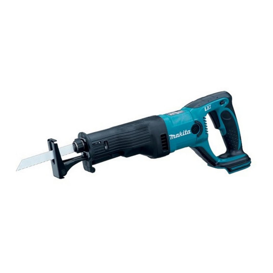
BJR141
Cordless Recipro Saw
Battery
type
quantity
No
No
No
1
BL1430
2
=spm
1
wood
pipe
Li-ion battery BL1430
Assorted recipro saw blades
Plastic
carrying case
No
Yes
14.4
3.0
Li-ion
280
23 (7/8)
0 - 2,700
90 (3-1/2)
90 (3-1/2)
Yes
Yes
3.1 (6.8)
PRODUCT
P 1 /10
W
L
Dimensions: mm (")
Length (L)
466 (18-3/8)
Width (W)
79 (3-1/8)
Height (H)
226 (8-7/8)
H
Advertisement

Related Manuals for Makita MAKSTAR BJR141 Series


Summary of Contents for Makita MAKSTAR BJR141 Series
- Page 1 ECHNICAL INFORMATION PRODUCT P 1 /10 Models No. BJR141 Description Cordless Recipro Saw ONCEPT AND MAIN APPLICATIONS Model BJR141 has been developed as the successor model to the current Model JR140D 14.4V cordless recipro saw. While having the same basic construction as Model JR140D, features the following additional advantages;...
- Page 2 Assembling Pin 3 to Blade clamp section [2] LUBRICATION and ADHESIVE Lubrication: Apply Makita grease FA No.2 to the following portions designated with the black triangle to protect parts and product from unusual abrasion. (Fig. 1) Adhesive: When reusing threadlocker coated screws, be sure to apply adhesive before tightening.
- Page 3 P 3 /10 epair [3] DISASSEMBLY/ASSEMBLY [3] -1. Blade Clamp Section DISASSEMBLING 1) Remove Shoe as illustrated in Fig. 2. Note: If the Blade clamp section is positioned inside Gear housing, pull it out of Gear housing. Fig. 2 Turn Lever 60 in the direction of the arrow. By unscrewing Hex bolt M8x25, Shoe can now Remove Pan head screw M4x10.
- Page 4 P 4 /10 epair [3] -1. Blade Clamp Section (cont.) 4) While putting your finger on the top of Slider to close the slit of Slider, remove Pin 3 (of 19.8mm length) by pushing with a thin bar. (Fig. 5) Note: Be sure to put your finger on the top of Slider or Push plate will pop out from the slit of Slider.
- Page 5 P 5 /10 epair [3] -1. Blade Clamp Section (cont.) 3) Install Guide sleeve on Sleeve provisionally. Put Push plate into the slit of Slider as illustrated in Fig. 9. Note: 1. Push plate is not reversible when installed. 2. Guide sleeve is used as a jig in this step. Do not assemble to Slider yet. 4) Insert Push plate straight into Slider using recipro saw blade until the hole of Push plate is aligned with the hole of Slider.
-
Page 6: Slider Section
P 6 /10 epair [3] -2. Slider Section DISASSEMBLING 1) Remove Shoe. (See Fig. 2 in page 3.) 2) Remove Blade clamp section. (See [3] -1. Blade Clamp Section in pages 3 and 4.) 3) Remove Insulation cover; If replacing with new one, cut away using cutter knife. If reusing removed Insulation cover, remove as illustrated in Fig. - Page 7 (Recommended adhesives: Threebond 1342, Loctite 242) (Fig. 20) Note 4: Do not to forget to apply Makita grease FA No.2 to the crank portion of Slider. (Fig. 20) Note 5: When assembling Gear housing cover complete to Gear housing, tighten four M5x18 Pan head screws while pushing Gear housing cover complete against Motor housing (Fig.
-
Page 8: Motor Section
P 8/10 epair [3] -3. Spiral Bevel Gear Section (cont.) DISASSEMBLING 2) Fix Spiral bevel gear section in vise by clamping the flats of Gear shaft, then remove Torx socket head bolt M6x15 using Torx screwdriver applicable to T20 Torx socket. (Fig. 23) Note: Securely fit Torx driver in the socket of Torx socket head bolt M6x15 because Threadlocker is applied to the bolt. - Page 9 P 9/10 epair [3] -4. Motor Section (cont.) ASSEMBLING Do the reverse of the disassembling steps. Note: When inserting Armature into Motor housing, Armature will be pulled strong towards Motor housing by the magnet force of Yoke unit. Be careful not to damage the copper wire of Armature or not to pinch your fingers.
- Page 10 P 10/10 iring diagram 1) Motor Housing Route two Lead wires (black, red) from Brush holder as illustrated in Fig. 30. Fig. 30 black Motor housing Fix with the lead wire holder lead wire holder on Motor housing. on Motor housing Do not route over the rib rib on Motor housing on Motor housing.
Need help?
Do you have a question about the MAKSTAR BJR141 Series and is the answer not in the manual?
Questions and answers