Advertisement
产品介绍 Introduction
FS-iBS01 是一款采用 i-BUS2 协议适配富斯 AFHDS 3 增强版接收
机的光感转速传感器。设计小巧,易安装,PPX6 级别防水,实
时回传转速数据,转速测量精度 10RPM,适配多种模型使用。
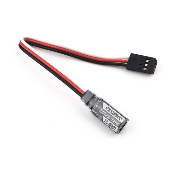
概览 Overview
[1]
[2]
[3]
舵机接口 /Interface
尺寸 /Dimensions:
产品规格 Product Specifications
• 产品型号:FS-iBS01
• 适配设备:支持 i-BUS2 协议系列接收机(如 FTr8B、
FTr12B、INr6-HS 等富斯 AFHDS 3 增强版接收机)
• 适配机型:车、船、飞机等
• 协议类型:i-BUS2
• 测量精度:10RPM
• 测量范围:60 ~ 300000RPM
• 输入电源:3.5~9V/DC
• 工作电流:20mA(5 V)
• 在线更新:不支持
• 防水等级:PPX6
• 外形尺寸:155mm(长度)
• 机身重量:4.0g
• 温度范围:-20℃ ~ +85℃
• 湿度范围:20% ~ 95%
• 安规认证:CE,FCC, UKCA
安装说明 Installation
光感转速传感器安装说明
安装步骤如下:
1. 使用 3M 贴将本传感器固定在模型合适
位置处 ( 如图),使光感探头与马达转
子反光面垂直,注意固定的面需平整。
也可使用扎带将其捆绑在模型上,注意
力度,避免扎带勒坏产品;
2. 如图所示,将舵机接口连接至接收机
Newport 接口,在与此接收机对码的发
射机端,将接收机对应的 Newport 接口
协议设置为 i-BUS2,即可在发射机端查
看相关信息。
注:
1. 将本传感器安装在靠近桨叶或马达转子
的位置,且光感探头与与桨叶或转子间距
离不超过 50mm 或 30mm(带遮光罩);
2. 不同应用对线材长度要求不同,如需加延
长线, 请注意 FS-iBS01 接口为舵机接口,
针脚定义参考前面【概览】描述。
3. 适配支持 i-BUS2 协议的发射机:Noble
(固件版本 V2.0.93 及以上) 、 Noble Lite ( 固
件版本 V1.0.10 及以上)、Noble pro、
PL18(固件版本 1.0.55 及以上)和 PL18
Lite(固件版本 1.0.65 及以上);
4. 光感转速传感器正常工作时, LED 灯常亮 ;
5. 若光感转速传感器已连接电源但未检测到
i-BUS2 信号,此时 LED 灯慢闪。
遮光罩使用说明
若在室外强光下使用本传感器,强烈的光线
会导致本传感器测量出现误差, 在此情况下,
Http://www.flysky-cn.com
Copyright ©2022 Flysky Technology co., ltd.
FS-iBS01
[4]
155mm
155mm
25mm
25mm
12mm
12mm
5mm
5mm
(厚度)
(厚度)
• Product Type: FS-iBS01
• Compatible Devices: The receivers with i-BUS2 protocol (such as FTr8B, FTr12B, INr6-
HS and other Flysky AFHDS 3 enhanced version receivers)
• Compatible Models: Cars, boats, airplanes, etc.
• Protocol: i-BUS2
• Measurement Accuracy: 10RPM
• Measurement Range: 60 ~ 300000RPM
• Input Power: 3.5 ~ 9V/DC
• Working Current: 20mA (5 V)
• Online Update: No
• Water Proof: PPX6
• Dimensions: 155mm (Length)
• Weight: 4.0g
• Temperature Range: -20℃ ~ + 85℃
• Humidity Range: 20% ~ 95%
• Certifications: CE, FCC, UKCA
Mounting Instruction
Follow the steps below to install:
1. Use 3M stickers to fix the optical perception sensor
at the appropriate location of the model as shown
in the figure. And make the optical perception
detection elementper pendicular to the reflective
surface of the motor rotor. It should be noted that
the fixed surface should be flat. You can also use
a cable tie to tie it to the model. In this case, you
should control the force.
2. Connect the servo interface to the Newport
interface of the receiver as shown. Set the protocol
of the corresponding Newport interface of the
receiver to i-BUS2 at the transmitter side that has
bound with this receiver. As a result, you can view
the relevant information at the transmitter side.
Notes:
1. Install this sensor close to the blade or motor rotor. The distance between the optical perception
detection element and the propeller or rotor is not more than 50 mm or 30 mm (with a light
shield).
2. The cable length may vary to different applications. If you need to add an extension cable,
please note that the FS-iBS01 interface is a servo interface, and for the pin definition, refer to the
description in the previous Overview section.
3. The transmitters that support i-BUS2 protocol: Noble (firmware version V2.0.93 or later), Noble
Lite (firmware version V1.0.10 or later), Noble pro, PL18 (firmware version 1.0.55 or later) and PL18
Lite (firmware version 1.0.65 or later).
4. If the optical perception sensor is working properly, the LED is solid on at this time.
5. If the optical perception sensor is connected to power supply but no i-BUS2 signal is detected, the
LED flashes slowly at this time.
Instructions for Use of the Light Shield
If the sensor is used under strong outdoor light, the strong light will cause measurement errors of
FS-iBS01 is an optical perception sensor that adapts to Flysky AFHDS 3 enhanced
version receiver in compliance with i-BUS2 protocol. It features compact design,
easy installation, PPX6 waterproof, real time rotate speed data return, rotate
speed measurement accuracy (10RPM), and adaption to a variety of models.
[1] S( 信号脚)
[5]
[2] + ( 电源正极)
[3] -( 电源负极 )
[4] LED 灯
[5] 光感探头
RPM sensor
(Optical perception)
[1] Signal pin
[2] + (Power anode)
[3] - (Power cathode)
[4] LED
[5] Optical perception detection element
安装示意图 /Installation Diagram
桨叶 /Propeller
传感器 /RPM Sensor
接收机 /Receiver
与接收机连接示意图 /Connection Diagram
Newport 接口 /Newport Interface
接收机 /Receiver
FS-iBS01
Advertisement
Table of Contents

Subscribe to Our Youtube Channel
Related Manuals for FlySky FS-iBS01


Summary of Contents for FlySky FS-iBS01
- Page 1 2. The cable length may vary to different applications. If you need to add an extension cable, 3. 适配支持 i-BUS2 协议的发射机:Noble please note that the FS-iBS01 interface is a servo interface, and for the pin definition, refer to the (固件版本 V2.0.93 及以上) 、 Noble Lite ( 固...
- Page 2 -- Consult the dealer or an experienced radio/TV technician for help. EU DoC Declaration Hereby, [Flysky Technology co., ltd] declares that the Radio Equipment [FS-iBS01] is in compliance with RED 2014/53/EU. The full text of the EU DoC is available at the following internet www.flyskytech.com/info_detail/10.html.
Need help?
Do you have a question about the FS-iBS01 and is the answer not in the manual?
Questions and answers