Table of Contents
Advertisement
Quick Links
U S E R ' S G U I D E
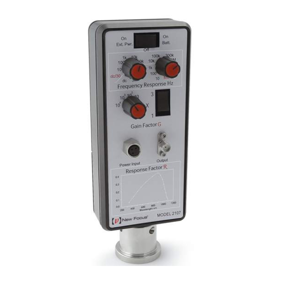
10-MHz Adjustable
Balanced Photoreceivers
Models 2107 & 2117
These photoreceivers are sensitive to electrostatic
discharges and could be permanently damaged if
subjected even to small discharges. Ground your-
self adequately prior to handling these detectors or
making connections. A ground strap provides the
most effective grounding and minimizes the
likelihood of electrostatic damage
e-mail: tech@newport.com • www.newport.com
phone: (877) 835-9620
Advertisement
Table of Contents

Subscribe to Our Youtube Channel
Related Manuals for Newport 2107


Summary of Contents for Newport 2107
- Page 1 U S E R ’ S G U I D E 10-MHz Adjustable Balanced Photoreceivers Models 2107 & 2117 These photoreceivers are sensitive to electrostatic discharges and could be permanently damaged if subjected even to small discharges. Ground your- self adequately prior to handling these detectors or making connections.
- Page 2 Warranty Newport Corporation guarantees its products to be free of defects for one year from the date of shipment. This is in lieu of all other guarantees, expressed or implied, and does not cover incidental or consequential loss. Information in this document is subject to change without notice.
-
Page 3: Table Of Contents
Physical Specifications ....... . . 21 Model 2107 Specifications ......22 Model 2117 Specifications . - Page 4 This page has been intentionally left blank 4 • Contents...
-
Page 5: Operation
2117-FS 900–1700 nm InGaAs 0.08 mm Complete specifications begin on page 21. Note: Note: The 10-MHz three-stage transimpedance amplifier includes selectable gain and selectable low- or high- pass filters for easy signal optimization. Models 2107 & 2117 Operation • 5... - Page 6 Figure 1: Typical 2117 responsivities of the Model 2107 & 2117 photodiodes 2107 1200 1600 Wavelength (nm) To obtain the value of the “response factor” in V/mW, Note: Note: divide the photodiode responsivity by 1.5. For more information on frequency response and noise, see page...
-
Page 7: Using The Photoreceiver
2. Supply power. Power the Model 21X7 using either two 9-volt alkaline batteries or a ±15-V low- noise linear power supply (such as the Newport Model 0901). 3. Connect the receiver output. Connect your voltmeter, oscilloscope, or other instrument to the Output SMA connector on the receiver. -
Page 8: Checking The Battery
Newport Model 0901. 1. Turn off the receiver using the power switch. 2. Use a Phillips-head screwdriver to remove the two screws on the back panel of the photoreceiver. -
Page 9: General Features & Principles
-9 V the Model 21X7 circuitry BATT -9 V REG -15 V ADJUSTABLE-GAIN STAGE +9 V INDEPENDENTLY ADJUSTABLE-GAIN ADJUSTABLE 6-dB/OCTAVE STAGE HIGH- AND LOW-PASS FILTERS DETECTOR HOUSING IS -9 V GROUNDED Models 2107 & 2117 General Features & Principles • 9... -
Page 10: Optical Power And Output Voltage
1x settings, and significantly decreases at the highest gain settings. There is little difference in frequency response between the visible (Model 2107) and IR (Model 2117) models. The plots of Figure 3 show the frequency-response details for each gain setting. - Page 11 We can calculate the saturation power at 900 nm for the Model 2107 at its ± maximum output voltage of 7 V with fresh batteries or operating from an external ±15 VDC power supply.
- Page 12 This page has been intentionally left blank 12 • General Features & Principles...
-
Page 13: Frequency Response And Noise
Minimum Optical Power = NEP · where BW is the bandwidth. Note that NEP is a wavelength-dependent quantity that changes with the photodetector’s responsivity. Models 2107 & 2117 Frequency Response and Noise • 13... - Page 14 235 kHz. This gives an optical noise equivalent power of about 390 pW, so the minimum detectable optical signal at 900 nm (with a signal-to- noise ratio of 1) for the Model 2107 on the highest gain 14 • Frequency Response and Noise...
- Page 15 G is the gain (V/V), R is the photodiode response factor (V/mW), NEP is the average noise equivalent power, and BW is the bandwidth. This gives an output noise voltage for the Model 2107 on the high gain setting of (3x10 V/V) ·...
-
Page 16: Performance Data For Frequency Response
The 3-dB frequency bandwidth is defined as the frequency where the photoreceiver’s transimpedance gain has decreased by a factor of . The typical frequency responses for the Model 2107 and Model 2117 are shown in the following figures. Figure 3: Gain Setting=1... - Page 17 Gain Setting=10 0.01 Frequency (MHz) Gain Setting=10 0.01 Frequency (MHz) Gain Setting=10 0.01 Frequency (MHz) Models 2107 & 2117 Frequency Response and Noise • 17...
-
Page 18: Performance Data For Noise
Performance Data for Noise Figure 4 shows the typical noise spectrum expressed as photocurrent noise for Model 21X7 photoreceivers on the highest gain setting. To derive the receiver’s Noise Equivalent Power (NEP), divide the photocurrent noise by the photodiode responsivity. To convert to output voltage noise (RMS), multiply the photocurrent noise by the gain setting from the 21X7 front label, then by 630 V/A (the scaling factor between the gain setting labels and the actual... -
Page 19: Common Mode Rejection
Thus, as seen in the following figures, the CMRR for higher gain settings is relatively flat to frequencies well beyond the useful frequency response of the gain setting. Models 2107 & 2117 Frequency Response and Noise • 19... - Page 20 Figure 5: Typical CMRR 1x10 - 3x10 Model 2107 in each gain 1 - 3x10 setting 1x10 - 3x10 0.01 Frequency (MHz) Figure 6: Typical CMRR Model 2117 in 1 - 3x10 each gain setting 1x10 - 3x10 1x10 - 3x10 0.01...
-
Page 21: Characteristics
Model 21X7 knob adjust knob casing photo- gain detectors gain knob multiplier 5.17" switch (131.2) external power 2.50" output input (63.5) connector (±15VDC) 8-32 (M4) 1.24" 2.31" (58.6) (31.5) Models 2107 & 2117 Characteristics • 21... -
Page 22: Model 2107 Specifications
Model 2107 Specifications Model 2107 Wavelength Range 300–1070 nm 3-dB Bandwidth 10 MHz, 5 MHz, 150 kHz Typical Common-Mode Rejection 25 dB Rise Time 80 ns Peak Conversion Gain 9.4 x 10 Typical Max. Responsivity 0.5 A/W Max. Transimpedance Gain 18.8 x 10... -
Page 23: Model 2117 Specifications
Detector Material/Type InGaAs/PIN Detector Active Area 0.3-mm diam. (FS) 0.1-mm diam. (FC) Optical Input FC or Free Space Electrical Output Power Requirements ±15 VDC <150 mA External Power Supply or Two 9-V Batteries Models 2107 & 2117 Characteristics • 23... -
Page 24: Customer Service
Customer Service Technical Support Information and advice about the operation of any Newport product is available from our applications engineers. For quickest response, ask for “Technical Support” and know the model number and serial number for your product. Hours: 8:00–5:00 PST, Monday through Friday (excluding holidays).
Need help?
Do you have a question about the 2107 and is the answer not in the manual?
Questions and answers