Table of Contents
Advertisement
Quick Links
U S E R ' S G U I D E
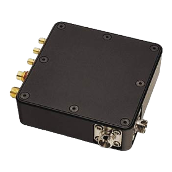
Balanced Photoreceivers
Models 1607-AC & 1617-AC
These photoreceivers are sensitive to electrostatic
discharges and could be permanently damaged if
subjected even to small discharges. Ground your-
self adequately prior to handling these detectors
or making connections. A ground strap provides
the most effective grounding and minimizes the
likelihood of electrostatic damage
e-mail: tech@newport.com • www.newport.com
phone: (877) 835-9620
Advertisement
Table of Contents

Subscribe to Our Youtube Channel
Related Manuals for Newport 1607-AC


Summary of Contents for Newport 1607-AC
- Page 1 U S E R ’ S G U I D E Balanced Photoreceivers Models 1607-AC & 1617-AC These photoreceivers are sensitive to electrostatic discharges and could be permanently damaged if subjected even to small discharges. Ground your- self adequately prior to handling these detectors or making connections.
- Page 2 Warranty Newport Corporation guarantees its products to be free of defects for one year from the date of shipment. This is in lieu of all other guarantees, expressed or implied, and does not cover incidental or consequential loss. Information in this document is subject to change without notice.
-
Page 3: Table Of Contents
Contents Introduction Overview ........5 Quick Start ....... . . 5 General Principles . - Page 4 This page has been intentionally left blank 4 • Contents...
-
Page 5: Introduction
Introduction Overview The Newport Model 16X7-AC balanced photoreceiver consists of two matched photodiodes and an RF amplifier that generates an output voltage proportional to I , the difference between the photocurrents in the two photodiodes. The Quick Start and General Principles sections... - Page 6 1. Use one of the supplied power cables to connect the photoreceiver to a ±15-volt power source that can supply 200 mA. (Page 11.) For the Newport Model 0901 power supply, use the 0923 power cable. For other power supplies, use the 0924 banana plug power cable.
-
Page 7: General Principles
General Principles The Newport Model 16X7-AC balanced photoreceiver consists of two matched photodiodes and an RF amplifier that generates an output voltage proportional to I , the difference between the photo-currents in the two photodiodes. A functional block diagram of the balanced photoreceiver is shown in Figure 1, and a mechanical drawing is given in Figure 2. - Page 8 DC to 100 kHz. Responsivity and Input Power The Model 1607-AC uses a matched pair of silicon photodiodes, and the Model 1617-AC uses a matched pair of InGaAs photodiodes. Figure 3 shows the typical responsivity of the photodiodes.
- Page 9 From the bandwidths, we estimate rise times of 0.8 ns for the 1607-AC and 0.6 ns for the 1617-AC. Figures 4 and 5 also show the typical noise spectrum. Since the RF amplifier is the dominant source of noise, the noise spectrum is the same for both the 1607-AC and 1617-AC.
- Page 10 3 µW for the Model 1607-AC and 1.5 µW for the Model 1617- AC. This input optical noise level is the approximate minimum optical signal that can be detected with these photoreceivers.
-
Page 11: Operation
Use the Model 0924 Pico (m8) male to banana plug power cable when working with a power supply other than the Newport Model 0901. Be sure to hook up the banana plugs correctly, or the photoreceiver can be damaged. The convention for the three banana plugs Balanced Photoreceivers Operation •... -
Page 12: Mounting The Photoreceiver
If the current draw is greater than 150 mA, then the cable could be shorted or there may be an internal problem with the photo- receiver. Contact Newport for support and, if necessary, instructions on returning the unit. Mounting the Photoreceiver The bottom of the photoreceiver has two pairs of holes for mounting it to a post or pedestal. -
Page 13: Connecting The Electrical Output
Overfilling the photodiode can cause a decrease in the photoreceiver’s frequency bandwidth. To avoid this, you may need to focus the beam onto the photodiode. The 1607-AC has a 0.4-mm diameter photodiode, and the 1617-AC has a 0.1-mm diameter photodiode. Using the FC Fiber-Coupled Model For fiber-optic input, connect the fiber-optic cable... -
Page 14: Testing The Photoreceiver
5. Connect the high-frequency RF Out SMA connector to the desired load or instrument via a 50-W coaxial cable. This output has a 50-W impedance and is AC-coupled with a 40-kHz low-frequency roll-off. Testing the Photoreceiver To quickly test whether the photoreceiver is working, you can perform a simple DC optical test. -
Page 15: Customer Service
Customer Service Technical Support Information and advice about the operation of any Newport product is available from our applications engineers. For quickest response, ask for “Technical Support” and know the model number and serial number for your product. Hours: 8:00–5:00 PST, Monday through Friday (excluding holidays). -
Page 16: Specifications
Specifications Model 1607-AC Model 1617-AC Wavelength Range 320–1000 nm 900–1700 nm 3-dB Bandwidth 40 kHz–650 MHz 40 kHz–800 MHz Rise Time (estimated) 0.8 ns 0.6 ns Typical Max. Responsivity 0.5 A/W 1.0 A/W Transimpedance Gain 700 V/A 700 V/A Max. Conversion Gain...
Need help?
Do you have a question about the 1607-AC and is the answer not in the manual?
Questions and answers