Bubble BOAT B1 Installer's Instructions
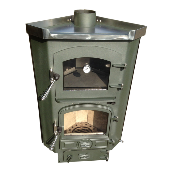
Corner oven oil appliance
Hide thumbs
Also See for BOAT B1:
- Installation instructions and owner's manual (12 pages) ,
- User instructions (17 pages)

Related Manuals for Bubble BOAT B1


Summary of Contents for Bubble BOAT B1
- Page 1 CORNER OVEN OIL APPLIANCE INSTALLER INSTRUCTIONS ISSUE 1 – 05-02-17 www.harworthheating.co.uk...
- Page 2 INDEX 1. BEFORE STARTING THE JOB............5 ABOUT THE APPLIANCE............................... 5 CONTROLS....................................6 2. SAFETY..................6 FUMES ......................................6 FIRE......................................6 BURNS......................................7 CLEARANCES FROM COMBUSTIBLES (APPLIANCE) ....................7 CLEARANCES FROM COMBUSTIBLES (FLUE) ........................ 7 VENTILATION.
-
Page 3: Table Of Contents
RUN OIL LINE. FIG 4 ................................9 TRIAL FIREPLACE ASSEMBLY............................9 TRY APPLIANCE IN POSTION............................9 ESTABLISH FLUE POSITION............................. 9 MARK OUT AND CUT THE ROOF PLATE........................10 FIT DECK FLANGE................................10 FIT FIRESTOP SPACER............................... 10 FIT CEILING PLATE. - Page 4 FLOW OF WATER THROUGH THE RADIATORS......................14 THE SYSTEM IS NOT OVER PUMPING.......................... 14 LACK OF PRESSURE RELEASE SAFETY VALVES......................14 FEED AND EXPANSION..............................14 9. FAULT FINDING COMBUSTION............14 1. RACING....................................14 2. FLUE VACUUM................................... 14 3.
- Page 5 disconnecting at the descaling device and then undo the straight compression joint and then remove the oil feed pipe from the valve. ABOUT THE APPLIANCE. Undo the single locking screw, disconnect the oil flow The corner oven appliance is a simple development of control rod and the thermostat control rod from the the corner oil appliance incorporating a small oven built oil control valve and the valve and plate should then...
- Page 6 it is vaporised and burned at a steady and controlled valve, should the stat trip. rate via gravity flow, metered by the OIL CONTROL The Toby valve has to be tripped into action by lifting VALVE. the trip button at the left hand side of the control The oil flow can be controlled from minimum to panel.
- Page 7 The rear of the upper oven is insulated and the Two fixing brackets are provided; these should be insulation is covered by a metal heat shield type plate. fitted over the oil drip tray up stand and fastened Do not remove the heat shields under any down through the hole provided.
- Page 8 If the bubble appliance is fitted up to the first bulkhead it will be necessary to fit the isolation valve There are several problems relating to diesel fuel outside the cabin or saloon of the boat.
-
Page 9: Run Oil Line. Fig 4
Two isolation valves are required, one fitted directly TRIAL FIREPLACE ASSEMBLY. into the oil control valve to allow you or the service TRY APPLIANCE IN POSTION. man to turn the oil off should the need arise, and one ESTABLISH FLUE POSITION. on the oil tank fitted before the filter. -
Page 10: Mark Out And Cut The Roof Plate
10mm at the top of the joint and pack remember that the whole essence of the Corner the gap with the flexible fire cement which will form a Bubble is to make the finished job look like a piece of seal. integrated design. -
Page 11: Calorifiers. Fig 5
If you are not suitably qualified, arrange for a heating Hep 2o with 15mm stabs to radiators. engineer to do the design and fitting work for you. Where additional radiators are fitted as heat leaks, See FIG 5 for schematic layout. the pipe work must be kept as short as possible, rise on feed and fall on return. -
Page 12: Fire Valve. Fig 4
Is it fitted-check for function and leaks? Make sure that adequate ventilation is provided in line Oil line- check for function, positioning, material with boat safety scheme. suitability and leaks. HYDRAULIC SYSTEMS. SEE FIG 5 Water systems should be pre-checked for leaks and tests must be made to make sure that water will flow freely through the boiler and that the boiler and pump is vented and free from trapped air. -
Page 13: Commissioning The High And Low Fire
let it stabilize. After stabilization there should be a dull red glow in the catalyser with wispy blue flames flickering just over the top of it, approximately level with the top of the pot. If the flame falls into a dirty rolling yellow flame and the catalyser is not dull red then the low fire will need to be increased until the burner can support the required blue flame combustion. -
Page 14: Air Locked System Pipework. Fig 5
AIR LOCKED SYSTEM PIPEWORK. FIG 5 Check that the chimney is working correctly. (This means pulling enough air into the burner to allow INADEQUATE SYSTEM PRESSURE HEAD. correct blue flame combustion to occur. INOPERATIVE CIRCULATING PUMP. FIG 5 Check that the fuel is the correct type and quality. Check that the flow rates are correct. -
Page 15: Routine Maintenance
OIL Flow rates in cc per minute. Section through corner appliance pot minus catalyser. 10cc Oil Flow Rates In litres per hour. .24 litres .6 litres Oil Flow Rates In litres per 24 hours. 5.76 litres 14.4 litres OUTER SKIN Oil Flow Rates In litres per 7 x 24 hours. -
Page 16: Warranty Items Not Covered
The warranty covers PARTS ONLY for a period of ONE YEAR and is conditional upon all the requirements Appliance ABOVE BELOW SIDES. BACK FRONT HEARTH Type BOAT B1 150 FROM HEAT 25 THICK X SHIELD BOAT B2 150 FROM HEAT... -
Page 18: Plumbing Layout Options
Each of the stoves has a different output to water and the installing engineer should first of all establish the boiler output to water and then design the heat losses accordingly. Note that some of the boilers can only provide heat for a calorifyer and towel rail. ©... - Page 19 CORNER OVEN OIL APPLIANCE INSTALLER INSTRUCTIONS ISSUE 1 – 05-02-17 www.harworthheating.co.uk...
- Page 20 INDEX 1. BEFORE STARTING THE JOB............5 ABOUT THE APPLIANCE............................... 5 CONTROLS....................................6 2. SAFETY..................6 FUMES ......................................6 FIRE......................................6 BURNS......................................7 CLEARANCES FROM COMBUSTIBLES (APPLIANCE) ....................7 CLEARANCES FROM COMBUSTIBLES (FLUE) ........................ 7 VENTILATION.
- Page 21 RUN OIL LINE. FIG 4 ................................9 TRIAL FIREPLACE ASSEMBLY............................9 TRY APPLIANCE IN POSTION............................9 ESTABLISH FLUE POSITION............................. 9 MARK OUT AND CUT THE ROOF PLATE........................10 FIT DECK FLANGE................................10 FIT FIRESTOP SPACER............................... 10 FIT CEILING PLATE.
- Page 22 FLOW OF WATER THROUGH THE RADIATORS......................14 THE SYSTEM IS NOT OVER PUMPING.......................... 14 LACK OF PRESSURE RELEASE SAFETY VALVES......................14 FEED AND EXPANSION..............................14 9. FAULT FINDING COMBUSTION............14 1. RACING....................................14 2. FLUE VACUUM................................... 14 3.
- Page 23 disconnecting at the descaling device and then undo the straight compression joint and then remove the oil feed pipe from the valve. ABOUT THE APPLIANCE. Undo the single locking screw, disconnect the oil flow The corner oven appliance is a simple development of control rod and the thermostat control rod from the the corner oil appliance incorporating a small oven built oil control valve and the valve and plate should then...
- Page 24 it is vaporised and burned at a steady and controlled valve, should the stat trip. rate via gravity flow, metered by the OIL CONTROL The Toby valve has to be tripped into action by lifting VALVE. the trip button at the left hand side of the control The oil flow can be controlled from minimum to panel.
- Page 25 The rear of the upper oven is insulated and the Two fixing brackets are provided; these should be insulation is covered by a metal heat shield type plate. fitted over the oil drip tray up stand and fastened Do not remove the heat shields under any down through the hole provided.
- Page 26 If the bubble appliance is fitted up to the first bulkhead it will be necessary to fit the isolation valve There are several problems relating to diesel fuel outside the cabin or saloon of the boat.
- Page 27 Two isolation valves are required, one fitted directly TRIAL FIREPLACE ASSEMBLY. into the oil control valve to allow you or the service TRY APPLIANCE IN POSTION. man to turn the oil off should the need arise, and one ESTABLISH FLUE POSITION. on the oil tank fitted before the filter.
- Page 28 10mm at the top of the joint and pack remember that the whole essence of the Corner the gap with the flexible fire cement which will form a Bubble is to make the finished job look like a piece of seal. integrated design.
- Page 29 If you are not suitably qualified, arrange for a heating Hep 2o with 15mm stabs to radiators. engineer to do the design and fitting work for you. Where additional radiators are fitted as heat leaks, See FIG 5 for schematic layout. the pipe work must be kept as short as possible, rise on feed and fall on return.
- Page 30 Is it fitted-check for function and leaks? Make sure that adequate ventilation is provided in line Oil line- check for function, positioning, material with boat safety scheme. suitability and leaks. HYDRAULIC SYSTEMS. SEE FIG 5 Water systems should be pre-checked for leaks and tests must be made to make sure that water will flow freely through the boiler and that the boiler and pump is vented and free from trapped air.
- Page 31 let it stabilize. After stabilization there should be a dull red glow in the catalyser with wispy blue flames flickering just over the top of it, approximately level with the top of the pot. If the flame falls into a dirty rolling yellow flame and the catalyser is not dull red then the low fire will need to be increased until the burner can support the required blue flame combustion.
- Page 32 AIR LOCKED SYSTEM PIPEWORK. FIG 5 Check that the chimney is working correctly. (This means pulling enough air into the burner to allow INADEQUATE SYSTEM PRESSURE HEAD. correct blue flame combustion to occur. INOPERATIVE CIRCULATING PUMP. FIG 5 Check that the fuel is the correct type and quality. Check that the flow rates are correct.
- Page 33 OIL Flow rates in cc per minute. Section through corner appliance pot minus catalyser. 10cc Oil Flow Rates In litres per hour. .24 litres .6 litres Oil Flow Rates In litres per 24 hours. 5.76 litres 14.4 litres OUTER SKIN Oil Flow Rates In litres per 7 x 24 hours.
- Page 34 The warranty covers PARTS ONLY for a period of ONE YEAR and is conditional upon all the requirements Appliance ABOVE BELOW SIDES. BACK FRONT HEARTH Type BOAT B1 150 FROM HEAT 25 THICK X SHIELD BOAT B2 150 FROM HEAT...
- Page 36 Each of the stoves has a different output to water and the installing engineer should first of all establish the boiler output to water and then design the heat losses accordingly. Note that some of the boilers can only provide heat for a calorifyer and towel rail. ©...
- Page 37 CORNER OVEN OIL APPLIANCE INSTALLER INSTRUCTIONS ISSUE 1 – 05-02-17 www.harworthheating.co.uk...
- Page 38 INDEX 1. BEFORE STARTING THE JOB............5 ABOUT THE APPLIANCE............................... 5 CONTROLS....................................6 2. SAFETY..................6 FUMES ......................................6 FIRE......................................6 BURNS......................................7 CLEARANCES FROM COMBUSTIBLES (APPLIANCE) ....................7 CLEARANCES FROM COMBUSTIBLES (FLUE) ........................ 7 VENTILATION.
- Page 39 RUN OIL LINE. FIG 4 ................................9 TRIAL FIREPLACE ASSEMBLY............................9 TRY APPLIANCE IN POSTION............................9 ESTABLISH FLUE POSITION............................. 9 MARK OUT AND CUT THE ROOF PLATE........................10 FIT DECK FLANGE................................10 FIT FIRESTOP SPACER............................... 10 FIT CEILING PLATE.
- Page 40 FLOW OF WATER THROUGH THE RADIATORS......................14 THE SYSTEM IS NOT OVER PUMPING.......................... 14 LACK OF PRESSURE RELEASE SAFETY VALVES......................14 FEED AND EXPANSION..............................14 9. FAULT FINDING COMBUSTION............14 1. RACING....................................14 2. FLUE VACUUM................................... 14 3.
- Page 41 disconnecting at the descaling device and then undo the straight compression joint and then remove the oil feed pipe from the valve. ABOUT THE APPLIANCE. Undo the single locking screw, disconnect the oil flow The corner oven appliance is a simple development of control rod and the thermostat control rod from the the corner oil appliance incorporating a small oven built oil control valve and the valve and plate should then...
- Page 42 it is vaporised and burned at a steady and controlled valve, should the stat trip. rate via gravity flow, metered by the OIL CONTROL The Toby valve has to be tripped into action by lifting VALVE. the trip button at the left hand side of the control The oil flow can be controlled from minimum to panel.
- Page 43 The rear of the upper oven is insulated and the Two fixing brackets are provided; these should be insulation is covered by a metal heat shield type plate. fitted over the oil drip tray up stand and fastened Do not remove the heat shields under any down through the hole provided.
- Page 44 If the bubble appliance is fitted up to the first bulkhead it will be necessary to fit the isolation valve There are several problems relating to diesel fuel outside the cabin or saloon of the boat.
- Page 45 Two isolation valves are required, one fitted directly TRIAL FIREPLACE ASSEMBLY. into the oil control valve to allow you or the service TRY APPLIANCE IN POSTION. man to turn the oil off should the need arise, and one ESTABLISH FLUE POSITION. on the oil tank fitted before the filter.
- Page 46 10mm at the top of the joint and pack remember that the whole essence of the Corner the gap with the flexible fire cement which will form a Bubble is to make the finished job look like a piece of seal. integrated design.
- Page 47 If you are not suitably qualified, arrange for a heating Hep 2o with 15mm stabs to radiators. engineer to do the design and fitting work for you. Where additional radiators are fitted as heat leaks, See FIG 5 for schematic layout. the pipe work must be kept as short as possible, rise on feed and fall on return.
- Page 48 Is it fitted-check for function and leaks? Make sure that adequate ventilation is provided in line Oil line- check for function, positioning, material with boat safety scheme. suitability and leaks. HYDRAULIC SYSTEMS. SEE FIG 5 Water systems should be pre-checked for leaks and tests must be made to make sure that water will flow freely through the boiler and that the boiler and pump is vented and free from trapped air.
- Page 49 let it stabilize. After stabilization there should be a dull red glow in the catalyser with wispy blue flames flickering just over the top of it, approximately level with the top of the pot. If the flame falls into a dirty rolling yellow flame and the catalyser is not dull red then the low fire will need to be increased until the burner can support the required blue flame combustion.
- Page 50 AIR LOCKED SYSTEM PIPEWORK. FIG 5 Check that the chimney is working correctly. (This means pulling enough air into the burner to allow INADEQUATE SYSTEM PRESSURE HEAD. correct blue flame combustion to occur. INOPERATIVE CIRCULATING PUMP. FIG 5 Check that the fuel is the correct type and quality. Check that the flow rates are correct.
- Page 51 OIL Flow rates in cc per minute. Section through corner appliance pot minus catalyser. 10cc Oil Flow Rates In litres per hour. .24 litres .6 litres Oil Flow Rates In litres per 24 hours. 5.76 litres 14.4 litres OUTER SKIN Oil Flow Rates In litres per 7 x 24 hours.
- Page 52 The warranty covers PARTS ONLY for a period of ONE YEAR and is conditional upon all the requirements Appliance ABOVE BELOW SIDES. BACK FRONT HEARTH Type BOAT B1 150 FROM HEAT 25 THICK X SHIELD BOAT B2 150 FROM HEAT...
- Page 54 Each of the stoves has a different output to water and the installing engineer should first of all establish the boiler output to water and then design the heat losses accordingly. Note that some of the boilers can only provide heat for a calorifyer and towel rail. ©...
- Page 55 CORNER OVEN OIL APPLIANCE INSTALLER INSTRUCTIONS ISSUE 1 – 05-02-17 www.harworthheating.co.uk...
- Page 56 INDEX 1. BEFORE STARTING THE JOB............5 ABOUT THE APPLIANCE............................... 5 CONTROLS....................................6 2. SAFETY..................6 FUMES ......................................6 FIRE......................................6 BURNS......................................7 CLEARANCES FROM COMBUSTIBLES (APPLIANCE) ....................7 CLEARANCES FROM COMBUSTIBLES (FLUE) ........................ 7 VENTILATION.
- Page 57 RUN OIL LINE. FIG 4 ................................9 TRIAL FIREPLACE ASSEMBLY............................9 TRY APPLIANCE IN POSTION............................9 ESTABLISH FLUE POSITION............................. 9 MARK OUT AND CUT THE ROOF PLATE........................10 FIT DECK FLANGE................................10 FIT FIRESTOP SPACER............................... 10 FIT CEILING PLATE.
- Page 58 FLOW OF WATER THROUGH THE RADIATORS......................14 THE SYSTEM IS NOT OVER PUMPING.......................... 14 LACK OF PRESSURE RELEASE SAFETY VALVES......................14 FEED AND EXPANSION..............................14 9. FAULT FINDING COMBUSTION............14 1. RACING....................................14 2. FLUE VACUUM................................... 14 3.
- Page 59 disconnecting at the descaling device and then undo the straight compression joint and then remove the oil feed pipe from the valve. ABOUT THE APPLIANCE. Undo the single locking screw, disconnect the oil flow The corner oven appliance is a simple development of control rod and the thermostat control rod from the the corner oil appliance incorporating a small oven built oil control valve and the valve and plate should then...
- Page 60 it is vaporised and burned at a steady and controlled valve, should the stat trip. rate via gravity flow, metered by the OIL CONTROL The Toby valve has to be tripped into action by lifting VALVE. the trip button at the left hand side of the control The oil flow can be controlled from minimum to panel.
- Page 61 The rear of the upper oven is insulated and the Two fixing brackets are provided; these should be insulation is covered by a metal heat shield type plate. fitted over the oil drip tray up stand and fastened Do not remove the heat shields under any down through the hole provided.
- Page 62 If the bubble appliance is fitted up to the first bulkhead it will be necessary to fit the isolation valve There are several problems relating to diesel fuel outside the cabin or saloon of the boat.
- Page 63 Two isolation valves are required, one fitted directly TRIAL FIREPLACE ASSEMBLY. into the oil control valve to allow you or the service TRY APPLIANCE IN POSTION. man to turn the oil off should the need arise, and one ESTABLISH FLUE POSITION. on the oil tank fitted before the filter.
- Page 64 10mm at the top of the joint and pack remember that the whole essence of the Corner the gap with the flexible fire cement which will form a Bubble is to make the finished job look like a piece of seal. integrated design.
- Page 65 If you are not suitably qualified, arrange for a heating Hep 2o with 15mm stabs to radiators. engineer to do the design and fitting work for you. Where additional radiators are fitted as heat leaks, See FIG 5 for schematic layout. the pipe work must be kept as short as possible, rise on feed and fall on return.
- Page 66 Is it fitted-check for function and leaks? Make sure that adequate ventilation is provided in line Oil line- check for function, positioning, material with boat safety scheme. suitability and leaks. HYDRAULIC SYSTEMS. SEE FIG 5 Water systems should be pre-checked for leaks and tests must be made to make sure that water will flow freely through the boiler and that the boiler and pump is vented and free from trapped air.
- Page 67 let it stabilize. After stabilization there should be a dull red glow in the catalyser with wispy blue flames flickering just over the top of it, approximately level with the top of the pot. If the flame falls into a dirty rolling yellow flame and the catalyser is not dull red then the low fire will need to be increased until the burner can support the required blue flame combustion.
- Page 68 AIR LOCKED SYSTEM PIPEWORK. FIG 5 Check that the chimney is working correctly. (This means pulling enough air into the burner to allow INADEQUATE SYSTEM PRESSURE HEAD. correct blue flame combustion to occur. INOPERATIVE CIRCULATING PUMP. FIG 5 Check that the fuel is the correct type and quality. Check that the flow rates are correct.
- Page 69 OIL Flow rates in cc per minute. Section through corner appliance pot minus catalyser. 10cc Oil Flow Rates In litres per hour. .24 litres .6 litres Oil Flow Rates In litres per 24 hours. 5.76 litres 14.4 litres OUTER SKIN Oil Flow Rates In litres per 7 x 24 hours.
- Page 70 The warranty covers PARTS ONLY for a period of ONE YEAR and is conditional upon all the requirements Appliance ABOVE BELOW SIDES. BACK FRONT HEARTH Type BOAT B1 150 FROM HEAT 25 THICK X SHIELD BOAT B2 150 FROM HEAT...
- Page 72 Each of the stoves has a different output to water and the installing engineer should first of all establish the boiler output to water and then design the heat losses accordingly. Note that some of the boilers can only provide heat for a calorifyer and towel rail. ©...
- Page 73 CORNER OVEN OIL APPLIANCE INSTALLER INSTRUCTIONS ISSUE 1 – 05-02-17 www.harworthheating.co.uk...
- Page 74 INDEX 1. BEFORE STARTING THE JOB............5 ABOUT THE APPLIANCE............................... 5 CONTROLS....................................6 2. SAFETY..................6 FUMES ......................................6 FIRE......................................6 BURNS......................................7 CLEARANCES FROM COMBUSTIBLES (APPLIANCE) ....................7 CLEARANCES FROM COMBUSTIBLES (FLUE) ........................ 7 VENTILATION.
- Page 75 RUN OIL LINE. FIG 4 ................................9 TRIAL FIREPLACE ASSEMBLY............................9 TRY APPLIANCE IN POSTION............................9 ESTABLISH FLUE POSITION............................. 9 MARK OUT AND CUT THE ROOF PLATE........................10 FIT DECK FLANGE................................10 FIT FIRESTOP SPACER............................... 10 FIT CEILING PLATE.
- Page 76 FLOW OF WATER THROUGH THE RADIATORS......................14 THE SYSTEM IS NOT OVER PUMPING.......................... 14 LACK OF PRESSURE RELEASE SAFETY VALVES......................14 FEED AND EXPANSION..............................14 9. FAULT FINDING COMBUSTION............14 1. RACING....................................14 2. FLUE VACUUM................................... 14 3.
- Page 77 disconnecting at the descaling device and then undo the straight compression joint and then remove the oil feed pipe from the valve. ABOUT THE APPLIANCE. Undo the single locking screw, disconnect the oil flow The corner oven appliance is a simple development of control rod and the thermostat control rod from the the corner oil appliance incorporating a small oven built oil control valve and the valve and plate should then...
- Page 78 it is vaporised and burned at a steady and controlled valve, should the stat trip. rate via gravity flow, metered by the OIL CONTROL The Toby valve has to be tripped into action by lifting VALVE. the trip button at the left hand side of the control The oil flow can be controlled from minimum to panel.
- Page 79 The rear of the upper oven is insulated and the Two fixing brackets are provided; these should be insulation is covered by a metal heat shield type plate. fitted over the oil drip tray up stand and fastened Do not remove the heat shields under any down through the hole provided.
- Page 80 If the bubble appliance is fitted up to the first bulkhead it will be necessary to fit the isolation valve There are several problems relating to diesel fuel outside the cabin or saloon of the boat.
- Page 81 Two isolation valves are required, one fitted directly TRIAL FIREPLACE ASSEMBLY. into the oil control valve to allow you or the service TRY APPLIANCE IN POSTION. man to turn the oil off should the need arise, and one ESTABLISH FLUE POSITION. on the oil tank fitted before the filter.
- Page 82 10mm at the top of the joint and pack remember that the whole essence of the Corner the gap with the flexible fire cement which will form a Bubble is to make the finished job look like a piece of seal. integrated design.
- Page 83 If you are not suitably qualified, arrange for a heating Hep 2o with 15mm stabs to radiators. engineer to do the design and fitting work for you. Where additional radiators are fitted as heat leaks, See FIG 5 for schematic layout. the pipe work must be kept as short as possible, rise on feed and fall on return.
- Page 84 Is it fitted-check for function and leaks? Make sure that adequate ventilation is provided in line Oil line- check for function, positioning, material with boat safety scheme. suitability and leaks. HYDRAULIC SYSTEMS. SEE FIG 5 Water systems should be pre-checked for leaks and tests must be made to make sure that water will flow freely through the boiler and that the boiler and pump is vented and free from trapped air.
- Page 85 let it stabilize. After stabilization there should be a dull red glow in the catalyser with wispy blue flames flickering just over the top of it, approximately level with the top of the pot. If the flame falls into a dirty rolling yellow flame and the catalyser is not dull red then the low fire will need to be increased until the burner can support the required blue flame combustion.
- Page 86 AIR LOCKED SYSTEM PIPEWORK. FIG 5 Check that the chimney is working correctly. (This means pulling enough air into the burner to allow INADEQUATE SYSTEM PRESSURE HEAD. correct blue flame combustion to occur. INOPERATIVE CIRCULATING PUMP. FIG 5 Check that the fuel is the correct type and quality. Check that the flow rates are correct.
- Page 87 OIL Flow rates in cc per minute. Section through corner appliance pot minus catalyser. 10cc Oil Flow Rates In litres per hour. .24 litres .6 litres Oil Flow Rates In litres per 24 hours. 5.76 litres 14.4 litres OUTER SKIN Oil Flow Rates In litres per 7 x 24 hours.
- Page 88 The warranty covers PARTS ONLY for a period of ONE YEAR and is conditional upon all the requirements Appliance ABOVE BELOW SIDES. BACK FRONT HEARTH Type BOAT B1 150 FROM HEAT 25 THICK X SHIELD BOAT B2 150 FROM HEAT...
- Page 90 Each of the stoves has a different output to water and the installing engineer should first of all establish the boiler output to water and then design the heat losses accordingly. Note that some of the boilers can only provide heat for a calorifyer and towel rail. ©...
Need help?
Do you have a question about the BOAT B1 and is the answer not in the manual?
Questions and answers