
Related Manuals for HEINKEL TOURIST 103 A-2 1965

Summary of Contents for HEINKEL TOURIST 103 A-2 1965
- Page 4 Should you, at any time, require additional technical information, please contact your local HEINKEL Dealer, who will be glad to assist you. It is our aim to make sure that your HEINKEL Scooter gives you entire satisfaction January 1965...
- Page 5 Scooter will readily give you the personal ser- vice which goes with it. Wherever you see the "HEINKEL SERVICE" Sign, your Tourist Scooter will get care- ful attention. At these Service Stations, trained and skilled mechanics with Special tools take...
- Page 6 (brown) Service Booklet. The life and trouble-free Service given by your HEINKEL TOURIST depends to a large extent upon the Running-in and Service Instructions being closely followed.
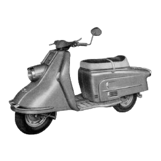
- Page 7 1. manufacturers' plate, 2. chassis number, 3. engine number, 4. oil dip stick.
- Page 8 chassis number engine number Number of steering lock key (i. e. number indicated on key head) NOTE! The key for steering lock and luggage compartment can only be replaced if you quote the key number. Therefore enter your key number in this booklet.
- Page 9 At Sports Meetings and Endurance Trials held in Europe and against fierce motor- cycle competition HEINKEL TOURIST Scooters always gain an impressive share of awards. Thus from 1958 through 1961 HEINKEL TOURIST riders received the following awards in 151 INTERNATIONAL and NATIONAL meetings: 414 GOLD MEDALS...
- Page 10 Mode of Operation 4-stroke o. h. v. 407 A-1 Output 9.5 h. p. at 5750 r. p. m. Number of cylinders Arrangement of cylinder vertical Bore 60 mm (2.36") diam. 61.5 mm (2.42") Stroke Swept capacity 174 cc Compression ratio 1:7.4 Valve arrangement overhead valves...
- Page 11 ignition 0.6 to 0.8 mm (0.0236" to 0.0315") before t. d. c. (using timing tool 404/W 10) 10° before t.d.c. Thermal coefficient of spark plug Spark gap 0.5 to 0.6 mm (0.02" to 0.024") Contact breaker gap 0.40 to 0.45 mm (0.0157" to 0.0177") Spark plug thread M 14x1.25 BING-Type 1/20/55...
- Page 12 4-speed type Gear Operation by twist-grip control on left handlebar Gear reduction 1st gear 3.51 :1 2nd gear 2.07 :1 3rd gear 1.38:1 4th gear 1 Reduction: Engine-Gearbox 1.88:1 Reduction: Gearbox-Rear wheel 2.73:1 3.10:1 Total reduction: gear 18.05:1 20.50:1 2nd gear 10.60:1 12.02:1 3rd gear...
- Page 13 torsion-free tubular steel Frame elastic three-point rubber Suspension Engine Suspension swing fork with two hydraulic telescopic Front wheel Suspension shock absorbers swinging arm with fully enclosed chain Rear wheel Suspension running in oil-bath; spring leg with hydraulic telescopic shock absorber shell handlebar unit with incorporated Handlebars speedometer...
- Page 14 Overall length 2020 mm (79.53") without luggage carrier Overall handlebar width 710 mm (27.95") without mirror 1000 mm (39.37") without mirror Overall height 750 mm (29.53") Saddle height 145 mm (5.70") Ground clearance Wheel base 1380 mm (54.33") Unladen weight, ready for travelling solo 148 kg (approx.
- Page 15 Fuel branded fuel, at least 82 octane (ROZ) Lubricant branded oil, SA 40 in summer SAE 30 in winter or Multigrade oil all the year round Fuel tank 12 litres (2.65 Imp. gals.) of which approx. 1.7 litres (0.38 Imp. gals.) form a reserve (latter sufficient for approx.
- Page 16 12 Volt Electrical equipment 2; each 6V10/11 Ah. flat batteries 140 mm ø with Bilux bulb 35/35 Watts built-in headlamp 4 Watts parking light 5 Watts tail light with licence plate light 18 Watts braking light 18 Watts blinking light blinking tell-tale light 2 Watts charging tell-tale light...
- Page 17 Performance and torque (1 PS = 1 DIN hp) (1 mkg = 7.233 ft Ib) (1 U/min = 1 r.p.m.) Number of engine revolutions when driving in the individual gears (1 U/min = 1 r.p.m.) (1 km/h = 0.621 mph)
- Page 18 Climbing power in the individuell gears (with a total weight of 250 kg) (1 km/h = 0.621 mph) (Steigung = gradient in %) Fuel consumption x Standard consumption (1 l/100 km = 282 m. p. Imp. gals. = 235 m. p. US. gals.) (1 km/h = 0.621 mph)
- Page 19 Maximum axle loading (approx. 275 Ibs.) admissible total weight 350 kg (approx. 528 Ibs.) (approx. 778 Ibs.)
- Page 20 1. Twist-grip throttle control 2. Front brake lever 3. Blinking light switch 4. Wide-scale speedometer 5. Charging tell-tale light 6. Tell-tale light (e. g. for headlight or oil temperature and the like) 7. Dipper switch 8. Overtaking light signal switch 9.
- Page 21 At fairly high engine speed, the red light goes out, thus indicating that the dynamo is charging the batteries. If red light fails to go out, either dynamo or governor switch is defective. Have them checked at a BOSCH or a HEINKEL Service Station.
- Page 22 indicates that blinkers are flashing (blue) on left side of handlebar Turn downwards for dipped beam Turn upwards for main beam (red) on left side of handlebar. Same is operated by alternately pushing and releasing red button. Operative only when ignition on. (green) on left side of handlebar.
- Page 23 engaged in ignition on, control starter operates engine (start all electric power consu- Iight on only with gears in 0-position., middle position mers switched i. e. in neutral) turn key to the parking Iight, ignition switched on; starter operates engine (gears in control light, parking neutral!) parking light, rear rear light and...
- Page 24 The running-in period is of vital importance to the future Service life and the reliability of your scooter. Even parts, which have been machined with utmost care, need a certain time for bedding down, and this can only be achieved by a very careful running-in of your scooter.
- Page 25 of at least 82 octane rating (ROZ). Fuel tank capacity approx. 12 litres (2.65 Imp. gals.), 1.7 litres (0.38 Imp. gals.) are reserve. Use only branded oil; SAE 40 in summer, SAE 30 in winter or multigrade all over the year. Oil should come up to top mark of dipstick.
- Page 26 1.0 atü (15 psi) 1.8 atü (26 psi) with pillion passenger 1.0 atü (15 psi) 2.0 atü (29 psi) driver solo with occupied sidecar 1.0 atü (15 psi) 2.5 atü (36 psi) 1.5 atü (22 psi) driver with pillion passenger, occupied sidecar and luggage 1.2 atü...
- Page 27 Main beam, dipper beam, parking light, tail light, braking light, blinking lights and horn should work. Open the inspection lid on the right- hand side of the rear cowling giving access to the fuel tap. Open the fuel tap. Before starting the engine make sure that gear control...
- Page 28 Open and dose the throttle twist-grip a few times briefly. Then push in the ignition key (red light comes on) beyond resistance to operafe Starter, at the same time slightly opening the throttle until engine Starts. After starting, release ignition key.
- Page 29 Place one foot in front of stand to avoid move- ment of same. Then grip the handlebars and roll scooter easily off its stand. Seat yourself com- fortably on the scooter. When the engine has been started (neutral gear), at Iow number of engine revolutions pull clutch lever and shift to first gear.
- Page 30 Disengage clutch in same manner as when changing into a higher gear, but open throttle briefly (according to speed) and then shift down into Iower gear and let in clutch gently. Before changing down to a Iower gear it is absolutely necessary to open the throttle briefly (with the clutch disengaged) in order to synchro- nize the speeds of the individual gear pinions...
- Page 31 Avoid locking of wheels because locked wheels have less braking power. Try always to use both brakes at the same time. Do not brake while negotiating curves, but when approaching them. Always shiftdown to Iower gear on steep slopes and, if necessary, use front and rear wheel brake alternately, so as to avoid overheating of brakes.
- Page 32 For parking the scooter, both legs of cen- tral stand should touch the ground simultaneously so as to distribute the weight of the scooter evenly and thus avoid damage to stand. Driving properly is a decisive factor also for the life span and operating costs of your scooter.
- Page 34 The crankshaft is suspended by two ball bearings. The chain wheel for driving the clutch (and thus the gears) is located on the left-hand side of the crankshaft. Starter- ignition-generating unit, ignition regulator and fan wheel are mounted on the right-hand side of the crankshaft.
- Page 35 The multiple-disc clutch, oil-bath immersed, is mounted on the clutch spindle. The engine output is transmitted from engine to clutch by a pitch chain. The clutch is operated from the clutch lever on the handlebar by an adjustable Bowden cable, fitted to the clutch worm.
- Page 37 Pump piston Air regulating screw Carburettor housing Valve plate Spring Evaporator air bore Cover plate Spring Clamp ring Clamp screw Cover thread G Pump jet needle Adjusting screw Float chamber Clamp bracket Float chamber cover H Main jet Gas piston W Float Cover screw Float needle...
- Page 38 The carburettor transforms the liquid fuel into a fuel-air mixture. The fuel is con- veyed to the float chamber of the carburettor through the banjo connection and hollow screw. The float, with float needle, keeps fuel in float chamber at a constant level;...
- Page 39 From time to time have this equip- ment checked by a specialist. Removal and reassembly of this unit should be carried out only at a HEINKEL- or BOSCH-service Workshop so as to avoid damage to crankshaft and dynamo.
- Page 40 The reliability of Operation and the service life of the scooter depend to a great extent on cleaning, care and maintenance. Very offen trouble and annoyance can be traced back to lack of proper care. Prior to washing of scooter remove paper air filter.
- Page 41 After washing, grease brake joints, centre stand and all moving parts. Use a propriet- ary chromium polish for the chromium-plated parts. To clean engine, remove rear body cowling as follows: 1. open the seat. 2. disconnect plugs for brake light, tail light and blinking light cables. 3.
- Page 42 Lubrication is of particular importance with a four-stroke engine and the instructions for oil-changing must therefore be strictly adhered to. Use only the recommended branded oils, i. e. multigrade for the whole year round or SAE 40 in summer and SAE 30 in winter.
- Page 43 Screw out the oil drain plug at the bottom of the crankcase (figure No. 7) and drain engine oil. Clean the thread of both plug and bore (in order to avoid seizing); then screw the drain plug loosely in again. For flushing fill up with 1.0 litres (1.75 Imp.
- Page 44 For technical reasons the engine is bound to consume some oil. When refilling for oil changes always use again the same oil brand that had been filled up before. Oil already containing chemical additives (added already by the oil companies) and oil lacking same are not to be mixed, as otherwise engine damage might develop.
- Page 45 Tilt scooter to left side, until foot- board touches ground, unscrew swing-arm cover. Drain oil by suc- tion. Check the links of the chain. To fill up, use branded oil SAE 40. Total oil filling approx. 150 to 200 c. c. When oil level is correct, oil reaches Iower edge of opening when scooter Stands almost up- right.
- Page 46 Readjust needle position and air regulating screw in accordance with factory instructions. If you should have any difficulty with the carburettor setting, do not hesitate to call on your HEINKEL-Service Sta- tion. Special Paper Air Filter 1. Filter insert 2. Bell-shaped filter housing 3.
- Page 47 If filter shows an unusually high amount of dust it should of course be replaced earlier. In town traffic and on tarred roads the filter insert will last about 5000 miles; on very dusty country roads a drop in per- formance and an increase in fuel consumption may well be noticed after a considerably shorter distan-...
- Page 48 Adjust valves, gap to be 0.15 mm (0.0059") for inlet and 0.20 mm (0.0079 )for exhaust valve. After setting valves, tighten locking nuts on adjusting screws. 1. inlet valve 2. exhaust valve Before starting work on the electrical equipment, always disconnect earthing cable from battery (to avoid danger of shortcircuiting).
- Page 49 Have this unit periodically checked by a BOSCH or HEINKEL-Service- Station. This Service check should include the following operations: 1. Readjust contact breaker; gap to be 0.4 to 0.45 mm (0.016" to 0.018") with contact breaker open. 2. Check ignition. Ignition timing to be 0.6 to 0.8 mm (0.0236"...
- Page 50 30 h magneto lead DF magneto cable B + 30 battery lead D + 61 50 Starter lead magneto cable 1. Leads for condensor and contact breaker 4. ignition lead 15. ignition switch lead...
- Page 51 Ignition coil and governor switch need no servicing. Periodically, however, check the lead connections on same and, if necessary, tighten them again. Check spark plug gap every 4000-8000 km (2.400 to 4.800 miles). It should be 0.5 to 0.6 mm (0.020" to 0.024"). The spark plug is accessible from the luggage boot;...
- Page 52 2 flat batteries of 6 V 11 Ah each. Check acid level every two weeks (in summer every week). Top up with distilled water, if necessary. Acid level should always be kept at 3 mm (0.12") above top edge of plates. Use only accumulator acid (sp. gr. 1.28) - Figure 25. See battery cover for battery maintenance and charging instructions.
- Page 53 At regular intervals, the setting of the headlamp should be checked and, if neces- sary, re-adjusted. This will ensure proper lighting of the road, increase your driving saftey and avoid endangering yourself and other road users. Check tyre pressure (front tyre 1.0 atü — 15 psi —, rear tyre 2.0 atü — 30 psi —). Set up scooter on its wheels on level ground and put on a load of either two persons or of 70 kg (155 Ibs) on each seat.
- Page 54 Switch over to main beam and check if headlamp is correctly set so that cross on the wall is in centre of lighted area. For correction proceed as explained for dimmed beam. Cross check with adjustment of dimmed beam.
- Page 55 Fuses 8 Amp. lead clamp screws clamp for lead to charging tell- tale light, blinking light switch and blinkinq light tell-tale lamp clamp for lead to brake light switch, handlebar switch 30 and horn clamp for lead to tail light, speed- ometer light and parking light clamp for lead to handlebar switch 56, for main beam and dipped...
- Page 56 1. lock nut 2. adjuster screw 3. lock nut 4. clutch cable adjuster screw 1. lock nut 2. adjuster screws for Bowden cable 3. shift lever 4. rubber tube...
- Page 57 The fuse-box is located at the right-hand top side of the leg shield. Undo screw, remove lid and the fuses are accessible. The engine Output is transmitted to the gearbox by means of a multiple-disc clutch and then on to the rear wheel. Clutch lever on handlebar should have 2-3 mm (0.08"...
- Page 58 "Upward" shifting (1-0-2-3-4) is transmitted by the Bowden cable, "downward" shifting (4-3-2-0-1) is transmitted by the Bowden cable. 1. Set twist-grip to "1"-position; gear lever on crank case must point towards clutch worm and 1st gear must be engaged. Turn twist-grip slowly to "0"-position (neutral), at the same time moving rear wheel forward and backwards.
- Page 59 1. Adjuster nut for Bowden cable of front wheel brake 2. Bolt 3. Brake lever nut 4. Brake lever 5. Rim nuts (SW 10) If handbrake lever produces no brake response after having cover- ed one fourth of its overall path, readjust front wheel brake (figure 22).
- Page 60 1. Lock nut 2. Adjusting screw for rear brake Bowden cable 3. Brake lever The adjuster screw for the rear brake is located on swinging arm (Figure 30). For readjustment, loosen lock nut and adjust screw. Tighten lock nut again. After adjust- ment the rear wheel should turn smoothly and without any uneven noise from brake shoes.
- Page 61 For more complicated operations such as brake repairs etc. please call on your HEINKEL-Service Station. Disconnect return spring, turn spring plate as indicated by arrow on figure No. 24, remove pedal pivot...
- Page 62 bolt. Disconnect foot brake Bowden cable both on brake lever and brake pedal. Remove pedal. For reassembly of pedal, reverse above procedure. Disconnect Bowden cable for front wheel brake and screw out speedometer spiral; loosen both axle nuts until the washers come off the recesses on front fork. Tilt scooter to right side until the footboard rests on the ground.
- Page 63 Wheel nuts (SW 14) 2. Rim screws (weldea-in) Tilt the scooter fo the right and rest it on the footplate. Unscrew the 5 wheel nuts with a box spanner (SW 14) and lift the wheel off the hub. For reas- sembly, reverse above procedure.
- Page 64 Tyre changing is very easy, as the wheel is composed of two split rims, held together by bolts and nuts. When removing tyre and tube never use sharp tools (screwdriver etc.) Never undo rim nuts, when tyres are still inflated as otherwise tyres likely to blow off.
- Page 65 Reassemble without play. The above operations can best be carried out by HEINKEL agents who are equipped to ensure that the reassembly is carried out properly. 1. Greasing nipple for swing fork 2.
- Page 66 The speedometer drive should be lubricated its greasing nipple every 4.000 km (approx. 2.400 miles). For lubricating, use ball-bearing grease. Prior greasing, unscrew clamp screw for speedometer spiral and dis- connect spiral and drive; refit same after lubricating. 1. Greasing nipple 2.
- Page 67 1. Fixing screw 2. Clamp screw for exhaust silencer If you drive your scooter during the winter, take care to drive accord- ing to road conditions and apply brakes very cautiously. If the average temperature drops below + 5° C. (40° F) the engine must be filled up with winter oil SAE 30 (provided no multigrade oil is used all year).
- Page 68 When driving in very hot weather or in tropical countries, both the inspection lid on right side of rear cowling - which gives access to carburettor and fuel tap - and the seat should be opened after every stop to provide Ventilation and cooling. Acid level in the batteries should be checked every week, and, if necessary, batteries should be topped up with distilled water.
- Page 69 3. Unscrew spark plug. Through the spark plug bore spray in approx. 20-30 cc. of anti-corrosion oil. Operate Starter briefly, so that the engine turns over a few times; then place piston at top dead centre with the valves closed and screw spark plug in.
- Page 70 refill tank 1. Fuel tank empty 2. Fuel tap closed or not set for open fuel tap or set for reserve reserve 3. Fuel system blocked clear system by blowing through it with compressed air 4. Jets blocked clear jets by blowing through (do dis- mantle accelerator pump) close fuel tap, open throttle fully, depress...
- Page 71 2. Battery leads corroded clean, tighten and grease battery leads 3. Short-circuit in wiring System have wiring checked at a Service Station 4. Magneto coil in regulator Have magneto coil and wiring checked by disconnected BOSCH or HEINKEL service Station.
- Page 72 1. fuel tank empty fill up with fuel 2. fuel in tank down to reserve put fuel tap at reserve position level 3. fuel pipe clogged clean fuel pipe by blowing through 4. jets clogged blow through jets (do not dismantle accelerator pump!) 5.
- Page 73 1. Wrong sparking plug fit correct plug (225) 2. Wrong ignition timing check and adjust (retarded ignition 0.6 to 0.8 mm (0.0236" to 0.0315") before t. d. c. measured by timing tool 404/W 10) 3. Engine needs oil check oil level in engine and fill up, if necessary 4.
- Page 74 miles every 1400 1. Change engine oil 2000 2. Test run with the following functional checks a) clutch (check for play and correct engaging) b) switching (check left-hand handlebar twist grip for easy engaging of gears and easy operating) 2000 1400 c) brakes (efficiency) 3.
- Page 75 every miles 13. Clean spark plug, adjust electrodes, check ignition timing 4000 2800 14. Check contact breaker gap; if necessary, readjust, check ignition timing 4000 2800 15. Grease lubricating felt on contact breaker cam 4000 2800 16. Retighten engine fixation bolts 4000 2800 17.
- Page 76 Preface Carburettor Service Starter-ignition-generating unit Location of chassis and engine Scooter cleaning, care and numbers maintenance Technical data Engine maintenance Diagrams Checking the engine oil level Loading schedule Changing of oil in swinging arm 44 Controls Carburettor cleaning Running-in and driving instructions 23 Special Paper Air Filter Starting preparations Adjusting the Valves...
- Page 77 Adjusting front wheel brake Speedometer drive Adjusting rear wheel brake Exhaust assy Removing foot brake pedal Winter Driving and Operation Changing front wheel Summer Driving and Operation Changing rear wheel Storing of scooter Changing tyres Taking the scooter out of storage Removing tyres Breakdowns Fitting tyres...
Need help?
Do you have a question about the TOURIST 103 A-2 1965 and is the answer not in the manual?
Questions and answers