
Related Manuals for Digital Systems Tytan SAT DS520

Summary of Contents for Digital Systems Tytan SAT DS520
- Page 1 Technical documentation Tytan®SAT DS520 Tytan®SAT DS520B GSM/GPS/GLONASS device for telemonitoring and supervision of vehicles and technical appliances Digital Systems DS520.IM.EN.0205.008...
- Page 2 - Corrected diagram of DS18B20 thermometer connection DS520.IM.EN.0017.006 2017.06.12 - Additional analogue input mode (2.3, 6.4.1, 8.4.2, 8.4.3) DS520.IM.EN.0202.007 2018.06.04 - Description of battery version added DS520.IM.EN.0205.008 2018.08.21 - Corrected description of UPGRADE, GETCONFIG and SETCONFIG commands Digital Systems DS520.IM.EN.0205.008...
-
Page 3: Table Of Contents
Installation/changing of SIM card in DS520 ................23 Connection/disconnection of internal battery (DS520B only) ..........24 Mounting of DS520 unit in the vehicle .................. 26 Mounting of GSM antenna ....................27 Mounting of GPS/GLONASS antenna ..................29 Digital Systems DS520.IM.EN.0205.008... - Page 4 NC (normally closed) pushbutton switched to power supply voltage ......44 Software for DS520 configuration and testing ................45 Configuration management ....................46 Signal monitor ........................47 Measurement data monitor ....................49 7.3.1 GPS/GSM/other ......................49 7.3.2 Voltage measurement ....................51 Digital Systems DS520.IM.EN.0205.008...
- Page 5 GSM/ignition/power saving settings ................73 9.2.2 Digital inputs ........................73 9.2.3 Analogue inputs ......................74 9.2.4 Driver’s identification with iButton DS1990A/immobiliser ........... 74 9.2.5 Temperature measurement by DS18B20 temperature sensors ........74 9.2.6 Change of report generation parameters ..............75 Digital Systems DS520.IM.EN.0205.008...
- Page 6 Sending the file with current DS520 configuration to FTP server ......... 90 12.2.1 Command ........................90 12.2.2 Example ......................... 91 12.3 DS520 firmware update via firmware file downloaded from FTP server ......92 12.3.1 Command ........................92 12.3.2 Example ......................... 93 Digital Systems DS520.IM.EN.0205.008...
-
Page 7: General Characteristics
• Quad-band GSM/GPRS modem Simcomm SIM800C. • External GSM antenna. • Built-in GPS/GLONASS receiver Tytan Digital Systems GPS/GLONASS 1537 with simultaneous observation of GPS and GLONASS satellites. • External GPS/GLONASS antenna. • 32-bit Microchip MX7 microcontroller, 512kB Flash ROM, 128kB RAM. -
Page 8: Package Contents
A complete set of DS520 includes: • DS520 unit • dedicated 11-wire harness (loom) • GSM antenna • active GPS/GLONASS antenna SIM card of miniSIM type is not included in the set. The picture shows it only to specify the card size. Digital Systems DS520.IM.EN.0205.008... -
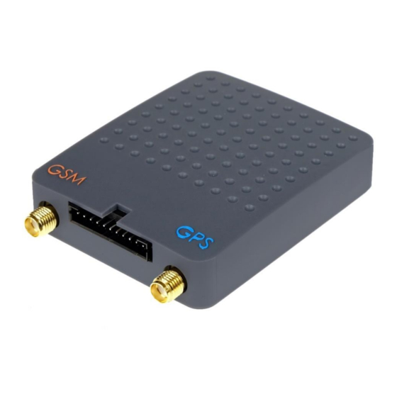
Page 9: View And Dimensions
1.4 View and dimensions Digital Systems DS520.IM.EN.0205.008... -
Page 10: Functionality
Device Advanced diagnostic tools for PC use, improving device installation and start-up. diagnostics Internal battery Device emergency operation in case of power supply lost. Depending on configuration and conditions: from several minutes up to 24h. Digital Systems DS520.IM.EN.0205.008... -
Page 11: Technical Data
Maximum output current (ON state) Electronic switch resistance(ON state) mΩ Protections Reverse polarity protection reversable, electronic Device overcurrent protection non-reversable, internal fuse 3A Output short-circuit protection electronic 1.7A 1-wire line overcurrent protection electronic, reversable, fuse50mA 1-wire overvoltage protection electronic, 5.6V Digital Systems DS520.IM.EN.0205.008... -
Page 12: Mechanical Features
Weight (DS520B) Material Poliamid PA66 + Fiber Glass Connectors & cables GPS connector GSM connector Cable loom connector JST PHR-11 Wires in cable loom UL1007 26AWG 12/0.12CU+PVC1.3 USB connector mini USB SIM card connector mini SIM, foldable Digital Systems DS520.IM.EN.0205.008... -
Page 13: Led Signals
- GPRS data transmission to the server possible. LED flashes rarely (every two seconds) WARNING! - In normal operation both LEDs should flash infrequently (every 2 seconds). - After power supply is connected (after restart) both LEDs light up continuously for 15 seconds. Digital Systems DS520.IM.EN.0205.008... -
Page 14: Device Description
4mA. WARNING! (a) Waking up the device from deepsleep mode causes opening a new GPRS session and, depending on GPRS service provider tariff charging system, can cause data transfer rounding to full tariff units. Therefore entering Digital Systems DS520.IM.EN.0205.008... -
Page 15: Modem / Gps/Glonass Receiver
Complied with GSM phase 2/2+: Class 4, Class 1 • SMS and GPRS handling GPS/GLONASS receiver The device is also supplied with GPS/GLONASS receiver manufactured on Digital Systems’ request: • designation: Tytan Digital Systems GPS/GLONASS 1537 • handles systems of GPS, Glonass, Galileo, QZSS •... -
Page 16: Analogue And Digital Inputs
Digital input value is transmitted to the server provided that data transmission from digital inputs has been enabled and operation mode for digital input has been configured. DI5 input is by default designed to operate as ignition input. Digital Systems DS520.IM.EN.0205.008... -
Page 17: Digital Outputs
USB interface USB interface enables device configuration and firmware upgrades. It allows monitoring real time values of measured data, using dedicated PC software. Digital Systems DS520.IM.EN.0205.008... -
Page 18: Power Supply From Internal Battery (Only Ds520B)
While keeping full tracker functionality, the device operation time is several dozens of minutes.. When power saving modes are used and report generation criteria are power-saving optimised it allows reaching 24h of device battery operation in standby mode. Digital Systems DS520.IM.EN.0205.008... - Page 19 (point 3.2.5). If external power supply is present, every start and finish of battery charging process also generates a report. If the device is in deepsleep mode, these events wake up the device in order to send these reports to the server. Digital Systems DS520.IM.EN.0205.008...
-
Page 20: Data Transmission To The Server
Otherwise, one packet (one transmission to the server) contains one report. The criteria described above (distance/angle/time when IGN ON/time when IGN OFF) are configured separately for 2 roaming situations: - local network (no roaming), - roaming – the device is outside the local network. Digital Systems DS520.IM.EN.0205.008... -
Page 21: Additional Reports Generation And Transmission When Special Events Appear
ID is saved. Turning ignition off for more than 30 seconds causes that iButton ID is removed from iButton memory and not sent to the server any more. This solution applies when iButton is used for driver’s identification during the Digital Systems DS520.IM.EN.0205.008... -
Page 22: Reports Concerning Internal Battery (Ds520B Only)
5 minutes delay as for the state when ignition is off. This solution reduces server connection timeout to a reasonable value when waiting for significant events data, with no need for immediate transmission (which would increase data transfer). On request the manufacturer may switch this function off. Digital Systems DS520.IM.EN.0205.008... -
Page 23: Installation Procedure
- remove the lower lid of the case, - shift SIM card holder in the direction marked by the "OPEN >" sign, - open the SIM card holder, - insert SIM card as shown in the picture, Digital Systems DS520.IM.EN.0205.008... -
Page 24: Connection/Disconnection Of Internal Battery (Ds520B Only)
DS520B is equipped with internal battery to maintain device operation when power supply is lost. Battery circuit has a jumper that connects and breaks battery circuit. For transport purposes, battery is disconnected from the tracker. During installation the battery must be connected to the device by use of the jumper. Digital Systems DS520.IM.EN.0205.008... - Page 25 LEDs!). The goldpin connector with the jumper should be above the case edge. - move the jumper to position A (battery disconnected) or position B (battery connected), - press the circuit board to its place in the case. Make sure the hooks clicked. Digital Systems DS520.IM.EN.0205.008...
-
Page 26: Mounting Of Ds520 Unit In The Vehicle
- It is advised to mount the unit inside the vehicle, in a well-hidden place, not accessible for the unauthorised person, e.g. under dashboard, behind the glove box, in the front or rear centre console, in the trunk etc. Digital Systems DS520.IM.EN.0205.008... -
Page 27: Mounting Of Gsm Antenna
- The GSM antenna should be installed inside the vehicle and should not be visible by any unauthorised person. - The GSM antenna must not be covered by any metal elements of the dashboard. It must not be glued to the metal elements of the vehicle. Digital Systems DS520.IM.EN.0205.008... - Page 28 - The GSM antenna cable must be laid and secured using cable ties or isolation tape. - The GSM antenna cable must be connected by the nut to the "GSM" marked metal connector of DS520 unit. Digital Systems DS520.IM.EN.0205.008...
-
Page 29: Mounting Of Gps/Glonass Antenna
The upper halfsphere over the antenna must not be covered with metal elements. - It is advised to install the GPS/GLONASS antenna in the middle of the dashboard, to have the windshield in the sphere above the antenna. Digital Systems DS520.IM.EN.0205.008... - Page 30 - The GPS/GLONASS antenna cable must be laid and secured using cable ties or isolation tape. - The GPS/GLONASS antenna cable must be connected by the nut to the "GPS" marked metal connector of DS520 unit. Digital Systems DS520.IM.EN.0205.008...
-
Page 31: Driver's Identification/Immobiliser Function
WARNING! If the iButton is taken out of the reader while the ignition is on, the vehicle is not stopped. The vehicle will be immobilised after the ignition is switched off and on again. Digital Systems DS520.IM.EN.0205.008... -
Page 32: Scenario No.4 - Authorisation Only By Authorised Ibutton / Id Sent Only If Ibutton Is In The Reader
WARNING! Please use a relay adapted to vehicle power supply voltage - this is essential for 24V vehicles! –and also adapted to the current flowing in the vehicle immobilised circuit. Digital Systems DS520.IM.EN.0205.008... -
Page 33: Use Of Immobiliser Function For Ibutton Scenario No.1 And No.3
- In order to disable output OUT0 send SMS command to DS520 or send GPRS command from the server to DS520. The immobiliser relay is disabled - the vehicle can be started. WARNING! Switching ignition off and on again causes re-immobilisation of the vehicle and requires immobiliser function bypass procedure to be repeated. Digital Systems DS520.IM.EN.0205.008... -
Page 34: Sound Signalisation Of Ibutton/Immobiliser Operation
- switching ignition on when the immobiliser is not authorised. WARNING! Please use a buzzer adapted to vehicle power supply voltage. When LED is connected, please use an appropriate LED current-limiting resistor. This is essential for 24V vehicles! Digital Systems DS520.IM.EN.0205.008... -
Page 35: Ds520 Connection Diagrams
6. DS520 connection diagrams 6.1 General diagram Digital Systems DS520.IM.EN.0205.008... -
Page 36: Ds520 Diagram Connector Description
1-wire bus high current polarisation required for 2-wire connection of DS18B20 temperature sensors. Ground Power supply Vehicle’s main power supply. 8V <U <40V, I =200mA, = 33mA (with GPS/GLONASS receiver) av 12v = 18mA (with GPS/GLONASS receiver) av 12v Digital Systems DS520.IM.EN.0205.008... -
Page 37: Connection Of 1-Wire Devices/Immobiliser Function
Scenarios of iButton operation (driver’s identification or immobiliser function) are described in chapter Rules of iButton ID transmission to the server is described in point 3.2.3. Wiring diagrams of iButtons and temperature probes are shown in points 6.3.1-6.3.3. Digital Systems DS520.IM.EN.0205.008... -
Page 38: Connection Of Ds18B20 Temperature Sensors
6.3.1 Connection of DS18B20 temperature sensors Digital Systems DS520.IM.EN.0205.008... -
Page 39: Connections For Immobiliser Operation (Ibutton Reader, Immobiliser Relay, Buzzer)
6.3.2 Connections for immobiliser operation (iButton reader, immobiliser relay, buzzer) Description of typical relay terminals: Digital Systems DS520.IM.EN.0205.008... -
Page 40: Connection Of Ds18B20 Temperature Sensors And Ibutton Reader
6.3.3 Connection of DS18B20 temperature sensors and iButton reader Digital Systems DS520.IM.EN.0205.008... -
Page 41: Connection Of Analogue Signals (Voltage Measurement)
– the square wave signal can be seen on the oscilloscope connected to AIx input. In this case, the option Peak voltage detector has to be enabled in the input configuration window. WARNING! Peak voltage detector can be enabled simultaneously only for one of the inputs. Digital Systems DS520.IM.EN.0205.008... -
Page 42: Connection Of Digital Fuel Level Sensor (Fls) With Analogue Output 0-10V
Most of the fuel level sensors on the market operate according to their own fuel level averaging algorithms. For this reason, in DS520 programmer the minimal signal averaging time has to be set to 10 seconds and peak voltage detector should not be enabled. Digital Systems DS520.IM.EN.0205.008... -
Page 43: Connection Of Digital Signals (On/Off)
- in Signal monitor Dlx input lamp does not light up, - in Signal monitor Dlx input lamp lights up, - „0” input state is transmitted to the server. - „1” input state is transmitted to the server. Digital Systems DS520.IM.EN.0205.008... -
Page 44: Nc (Normally Closed) Pushbutton Switched To Ground
WARNING! For NC switches in standby mode the input state marked with “1” is transmitted to the server. When the pushbutton is pressed the input state marked with “0” is sent. Please keep it in mind when report generation and immediate data transmission are configured for the digital input. Digital Systems DS520.IM.EN.0205.008... -
Page 45: Software For Ds520 Configuration And Testing
- Data monitor - displays numeric data: power supply voltage, signal level, etc. - 1-wire monitor - displays the list of 1-wire devices connected in a given moment. WARNING! Particular parameters of DS520 configuration are described in chapter 8. Digital Systems DS520.IM.EN.0205.008... -
Page 46: Configuration Management
(without displaying in The option allows writing directly on the computer disk the programmer and possibility of the configuration read from the device without the modification) possibility of modification in the programmer window. Used for service and diagnostic purposes. Digital Systems DS520.IM.EN.0205.008... -
Page 47: Signal Monitor
--> save copy of configuration file to the disk --> write configuration file to the device 7.2 Signal monitor When Signal monitor button is pressed a panel that allows to check the presence of input signals and the state of outputs is displayed. Digital Systems DS520.IM.EN.0205.008... - Page 48 Control lamp indicates that DI2/DI3/DI4/DI5 digital input detects active state (input trigger). The lamp signals: - positive voltage for input in mode INPUT+ and other (+), - connection to ground in mode INPUT- and other (-). Digital Systems DS520.IM.EN.0205.008...
-
Page 49: Measurement Data Monitor
When Data monitor button is pressed a panel that allows to preview live data and operation parameters is displayed. The panel is divided into separate tabs for the clarity. 7.3.1 GPS/GSM/other The tab presents GSM data, GPRS connection status and GPS/GLONASS signal. Digital Systems DS520.IM.EN.0205.008... - Page 50 Ok - data transmission to the server has been correct and acknowledged by the server. Wait - the device waits for the acknowledge of data reception from the server. Fail - the data transmission to the server has not been correct. Digital Systems DS520.IM.EN.0205.008...
-
Page 51: Voltage Measurement
Due to the way the inputs are polarized (described in sections 2.3 and 6.4), voltage for disabled digital inputs is equal to half of the measured power supply voltage. 7.4 iButton/1-wire monitor When iButton/1-wire monitor button is pressed a control panel for iButtons and 1-wire temperature sensors is displayed. Digital Systems DS520.IM.EN.0205.008... - Page 52 WARNING! iButton/1-wire monitor "captures" the signals read from 1-wire bus; as long as it is opened, the data read from iButton/1-wire devices are not transmitted to DS520 main application. For further checking of DS520 operation, the panel must be closed. Digital Systems DS520.IM.EN.0205.008...
-
Page 53: Parameters Of Ds520 Configuration
If SIM card requests a PIN code other than 6789, it can be inserted into DS520 only after writing the configuration and disconnecting both wire harness and USB cable! Value of this field depends on SIM card provider: tracking platform provider or GSM network operator. Digital Systems DS520.IM.EN.0205.008... -
Page 54: Reports/Data
The parameters are set separately for: - device operation in home network with external power supply, - device operation in home network from internal battery, - device operation in roaming with external power supply, - device operation in roaming from internal battery. Digital Systems DS520.IM.EN.0205.008... -
Page 55: Data Transmission
GLOBAL_IGNITION in the signal monitor (section 7.2) is on. every (3s-1000000s) Default value: 60 seconds. 8.2.5 Data transmission The tab collects settings related to the data transfer format and the operation of some DS520 functions. Digital Systems DS520.IM.EN.0205.008... - Page 56 These data are statistically significant and allow the (MCC+MNC, e.g. server to response to change of e.g. a country where the vehicle is in a given 26001) moment. As regular solutions these data are not needed. no – default setting Digital Systems DS520.IM.EN.0205.008...
-
Page 57: Power Supply/Ignition
This parameter activates power saving modes in the device, when operating on external (main power) power supply. disabled – default setting The device operates in the normal mode; it does not fall asleep; GPS receiver is enabled constantly. Power consumption reaches approx. 36 mA. GPS sleep mode enabled Digital Systems DS520.IM.EN.0205.008... - Page 58 – default setting The exact time of switching ignition on is known. The exact time of switching ignition on is not known – the ignition state is sent with the nearest report. Digital Systems DS520.IM.EN.0205.008...
- Page 59 Data on switching ignition off is sent to the server when time since last report reaches configured threshold (as described in section 8.2 – by default time between transmissions is up to 5 minutes). Digital Systems DS520.IM.EN.0205.008...
-
Page 60: Inputs
... as per TytanSAT protocol specification is sent to the server for unconfigured inputs. yes – default setting Voltage measured by inputDI2/DI3/DI4/DI5 is sent to the server if the input is configured for voltage measurement. Data from inputs DI2/DI3/DI4/DI5 are not sent to the server. Digital Systems DS520.IM.EN.0205.008... -
Page 61: Ai0 (Pin3, White/Black)
Peak voltage detector should be enabled in the following cases: - when analogue input momentary voltage is unstable (jumps) in the data monitor and has random values, - when square wave signal can be seen on the oscilloscope connected to analogue input. Digital Systems DS520.IM.EN.0205.008... -
Page 62: Di2 (Pin5, Light Blue)
The input detects “1”if voltage is greater than power supply voltage (short circuit to power supply voltage). The input detects “0” if voltage is lower than power supply voltage. Input signal is sent to the server as data [C5] in TytanSAT protocol. Digital Systems DS520.IM.EN.0205.008... - Page 63 - disconnect to power supply in private trip+ mode. no – default setting The exact time of input deactivation is not known – new input state is sent with the nearest report. The exact time of input deactivation is known. Digital Systems DS520.IM.EN.0205.008...
-
Page 64: Outputs/Immobiliser
(e.g. immobiliser) or pursuant to currently received remote command. Both outputs can have the same function, e.g. in order to control two immobiliser relays in an independent and tamper-resistant way. Digital Systems DS520.IM.EN.0205.008... -
Page 65: Ibutton/1-Wire
DS1990A identifiers The tab contains two parameters that switch globally data transmission from analogue and digital inputs. Input data are transmitted if parameter "{…} Sending .." has been enabled and the input has been configured in operation mode. Digital Systems DS520.IM.EN.0205.008... - Page 66 - output programmed in buzzer is controlled. {C10} Sending This parameter activates sending ID of authorised iButton that has been touched authorised iButton ID against the reader as the last one to the server. yes – default setting Digital Systems DS520.IM.EN.0205.008...
-
Page 67: Ibutton Drop-Down Menu
Delete a list of authorised iButtons’ IDs from the configuration programmer. Format of text file containing a list of iButton identifiers: 1C000009029FE301<CR><LF> 4C000009005ADE01<CR><LF> D80000089E07D801<CR><LF> F4000008FFA5EA01<CR><LF> FF000009027BFF01<CR><LF> where: <CR> - 13 code ASCII sign <LF> - 10 code ASCII sign Digital Systems DS520.IM.EN.0205.008... -
Page 68: Temperature Sensors Ds18B20
- add automatically in the 1-wire monitor (section 7.4): temperature sensor connect temp. sensor (or temp. sensors) and press Add to configuration button in the 1-wire monitor – IDs of temp. sensors connected to DS520 are added to configuration programmer. Digital Systems DS520.IM.EN.0205.008... -
Page 69: Configuration Procedure And Device Start-Up
(c) Read from the computer disk the file *.cfg with default settings for specified tracking platform (server) read from the computer disk the universal file with DS520 configuration. (d) Check in the GSM/GPRS settings tab (section 8.1): Digital Systems DS520.IM.EN.0205.008... - Page 70 - if vehicle vibrations and movements are supposed to be detected as switching ignition on: enable Ignition signal detected by accelerometer. WARNING! If there is no ignition signal wire, it is recommended to enable both below parameters: Ignition signal detected by accelerometer, Ignition signal detected by power supply voltage change. Digital Systems DS520.IM.EN.0205.008...
-
Page 71: Checking Device Operation For Basic Configuration (With Use Of Either Pc Or Leds)
–acc. to point 9.1.1 (f), start the engine and check if DS520 detects ignition signal in a few seconds (control lamps GLOBAL_IGNITION, IGN_(ACCELEROMETER) and IGN_(POWER SUPPLY) light up: Switch ignition off. Check if control lamps turn off in over a dozen of seconds. Digital Systems DS520.IM.EN.0205.008... - Page 72 DS520, that signals GSM connection, flashes rarely then (one flash in every 2 seconds). (k) Switch ignition on/switch ignition off. DS520 should generate and send a report to the server. Control lamp Connection Status should indicate „Waiting” and then „Ok”. Digital Systems DS520.IM.EN.0205.008...
-
Page 73: Advanced Configuration
→ on and on → off. For pushbuttons (returning to the initial state when released), it is sufficient to react only to the state change that is a result from pressing the pushbuttons. Digital Systems DS520.IM.EN.0205.008... -
Page 74: Analogue Inputs
OUT0 output as buzzer (iButton) acc. to section 8.5 and connect buzzer as shown in the diagram in point 6.3.2. 9.2.5 Temperature measurement by DS18B20 temperature sensors If DS520 is supposed to measure the temperature using DS18B20 temperature sensors, please follow the below steps: Digital Systems DS520.IM.EN.0205.008... -
Page 75: Change Of Report Generation Parameters
8.2.3 makes DS520 operate in the mode with fixed-length reports. Both modes are described in chapter 3. If DS520 is planned to be used in the mode with fixed-length reports, the user is advised to contact Digital Systems’ technical support. Digital Systems... -
Page 76: Sms/Gprs Commands. Remote Configuration And Firmware Upgrades
- In the example GPRS commands the responses are sent from the device with serial no. 5. - In the example command for new firmware downloading the address of actual Digital Systems company server with real firmware file is given. - Page 77 SMS sent to DS520: Message sent to DS520: iButtons and „12345 1wire” „*1wire” temperature SMS received from DS520: Message received from sensors „1WIRE,9E000005FC54A028,D DS520: connected to 1- 80000052DEB3328,32000005 „@00000005,1WIRE,9E00000 wire bus FCD8C728,CC0000052CF8772 5FC54A028,D80000052DEB33 8” 28,32000005FCD8C728,CC000 0052CF87728” Digital Systems DS520.IM.EN.0205.008...
- Page 78 ”*rconfig,192.168.0.11,515,in rconfig,185.17.41.184,50015,i ternet,internet,internet,TCP” nternet,,,udp” Message received from SMS received from DS520: DS520: „RCONFIG: IP=185.17.41.184- „@00000005,RCONFIG:IP=18 >185.17.41.184\nPORT=5001 5.17.41.184- 5->50015\nAPN=internet- >192.168.0.11,PORT=50015- >internet” >515,APN=internet- „RCONFIG:\n Al=->\n Ah=->\n >internet,Al=->internet,Ah=- SockType=UDP” >internet,SockType=TCP” Other possible responses: RCONFIG-recreated-ER {hexadecimal error number} RCONFIG-Error-{hexadecimal error number} Digital Systems DS520.IM.EN.0205.008...
- Page 79 SMS that informs about Message that informs about operation timeout: operation timeout: „GETCONFIG,TIMEOUT” „@00000005,GETCONFIG,TIM EOUT” SMS that informs about Message that informs about successful configuration successful configuration transmission to the server: transmission to the server: „GETCONFIG,COMPLETED” „@00000005,GETCONFIG,CO MPLETED” Digital Systems DS520.IM.EN.0205.008...
- Page 80 „SETCONFIG,DOWNLOAD- „@00000005,SETCONFIG,DO COMPLETED” WNLOAD-COMPLETED” SMS that informs about Message that informs about wrong command: wrong command: „SETCONFIG,ERROR-nr” – „@00000005,SETCONFIG,ERR where nr is an error number OR-nr” – where nr is an error Digital Systems DS520.IM.EN.0205.008...
- Page 81 SMS that informs that Message that informs that downloaded file is incorrect downloaded file is incorrect (improper CRC or signature): (improper CRC or signature): UPGRADE,DOWNLOAD- „@00000005,UPGRADE,DOW „ NLOAD-COMPLETED with COMPLETED with error X ” error X ” Digital Systems DS520.IM.EN.0205.008...
-
Page 82: Remote Configuration And Firmware Upgrade Via Sms
- when the format of transferred command is correct, SETCONFIG,DOWNLOAD-COMPLETED - after configuration file transmission is completed, SETCONFIG,ERROR-NR - when configuration file transmission error occurs, where NR- error number. After sending SMS confirmation, the device resets and restarts with new configuration settings. Digital Systems DS520.IM.EN.0205.008... -
Page 83: Example 1 - Downloading Configuration File With Automatically Generated Name
Then it attempts to download from FTP server the configuration file named myconfigfile.cfg As a confirmation of downloading configuration file from FTP server the device sends SMS with the following contents: SETCONFIG,DOWNLOAD-COMPLETED After sending SMS confirmation, the device resets and restarts with new configuration settings. Digital Systems DS520.IM.EN.0205.008... -
Page 84: Sending The File With Current Ds520 Configuration To Ftp Server
After configuration file transmission is completed successfully, a configuration file named id.cfg, where id is a device serial number shown as 4-byte hexadecimal number, is saved on FTP server. For unit with SN 31983 the file name is 00007CEF.cfg Digital Systems DS520.IM.EN.0205.008... -
Page 85: Example
As a confirmation of writing the configuration file to FTP server the device sends SMS with the following contents: GETCONFIG,COMPLETED The below screenshot taken from Total Commander presents the view of FTP server directory with the configuration file read from the unit with SN 31983. Digital Systems DS520.IM.EN.0205.008... -
Page 86: Ds520 Firmware Update Via Firmware File Downloaded From Ftp Server
11.3 DS520 firmware update via firmware file downloaded from FTP server To demonstrate the process of device firmware update the FTP server of Digital Systems company with the following parameters has been used: FTP server address (host): ftp.tytansat.com User’s login:... -
Page 87: Example
After the second part of DS520 firmware is downloaded properly: UPGRADE,FILE DS520_DS540_0005_CRC-B5BD-2-3.b64 DOWNLOAD-PART-2-OK After the third part of DS520 firmware is downloaded properly: UPGRADE,FILE DS520_DS540_0005_CRC-B5BD-3-3.b64 DOWNLOAD-PART-3-OK and then: UPGRADE,DOWNLOAD-COMPLETED Next, if configuration file has been transmitted correctly, the device resets and restarts with new configuration settings. Digital Systems DS520.IM.EN.0205.008... -
Page 88: Remote Configuration And Firmware Upgrade Via Gprs
- when the format of transferred command is correct, @id,SETCONFIG,DOWNLOAD-COMPLETED - after configuration file download is completed, @id,SETCONFIG,ERROR-NR - when configuration file download error occurs where NR – error number. After sending GPRS confirmations, the device resets and restarts with new configuration settings. Digital Systems DS520.IM.EN.0205.008... -
Page 89: Example 1 - Downloading Configuration File With Automatically Generated Name
Then it attempts to download from FTP server the configuration file named myconfigfile.cfg As a confirmation of downloading configuration file from FTP server the device sends text message to the server: @00007CEF,SETCONFIG,DOWNLOAD-COMPLETED After sending a GPRS confirmation, the device resets and restarts with new configuration settings. Digital Systems DS520.IM.EN.0205.008... -
Page 90: Sending The File With Current Ds520 Configuration To Ftp Server
4-byte hexadecimal number, e.g. for unit with SN 31983 the file name is 00007CEF.cfg NR – error number. After configuration file transmission is completed successfully, a configuration file named id.cfg is saved on FTP server. Digital Systems DS520.IM.EN.0205.008... -
Page 91: Example
As a confirmation of writing the configuration file to FTP server the device sends text message to the server: @00007CEF,GETCONFIG,COMPLETED The below screenshot taken from Total Commander presents the view of FTP server directory with the configuration file read from the unit with SN 31983. Digital Systems DS520.IM.EN.0205.008... -
Page 92: Ds520 Firmware Update Via Firmware File Downloaded From Ftp Server
12.3 DS520 firmware update via firmware file downloaded from FTP server To demonstrate the process of the device firmware update the FTP server of Digital Systems company with the following parameters has been used: FTP server address (host): ftp.tytansat.com User’s login:... -
Page 93: Example
After the second part of DS520 firmware is downloaded properly: @00007CEF,UPGRADE,FILE DS520_DS540_0005_CRC-B5BD-2-3.b64 DOWNLOAD-PART-2-OK After the third part of DS520 firmware is downloaded properly: @00007CEF,UPGRADE,FILE DS520_DS540_0005_CRC-B5BD-3-3.b64 DOWNLOAD-PART-3-OK and then: @00007CEF,UPGRADE,DOWNLOAD-COMPLETED Next, if configuration file has been transmitted correctly, the device resets. Digital Systems DS520.IM.EN.0205.008...
Need help?
Do you have a question about the Tytan SAT DS520 and is the answer not in the manual?
Questions and answers