Table of Contents
Advertisement
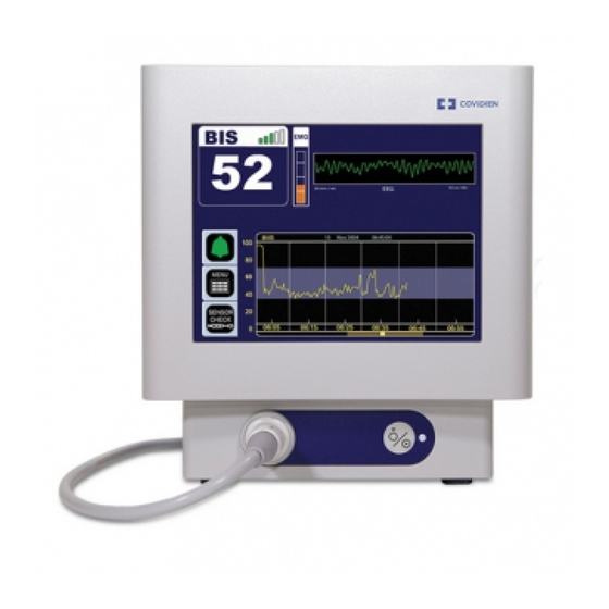
BIS VISTA™ Monitoring System
OPERATING MANUAL
Aspect Medical Systems, Inc.
One Upland Road
Norwood, MA 02062
U.S.A.
(Tel) 617-559-7000
(Tel) 888-BIS INDE(X) (U.S. only)
(Fax) 617-559-7400
bis_info@aspectms.com
www.aspectmedical.com
Rx only
EC REP
Aspect Medical Systems International B.V.
Rijnzathe 7d2
3454 PV De Meern
The Netherlands
Tel: +31.30.662.9140
Fax: +31.30.662.9150
amsint@aspectms.com
0123
070-0069 3.00
Advertisement
Table of Contents

Related Manuals for BIS VISTA

Summary of Contents for BIS VISTA
- Page 1 BIS VISTA™ Monitoring System OPERATING MANUAL Rx only EC REP Aspect Medical Systems, Inc. Aspect Medical Systems International B.V. One Upland Road Rijnzathe 7d2 Norwood, MA 02062 3454 PV De Meern U.S.A. The Netherlands 0123 (Tel) 617-559-7000 Tel: +31.30.662.9140 (Tel) 888-BIS INDE(X) (U.S. only) Fax: +31.30.662.9150...
- Page 3 BIS VISTA is a trademark of Aspect Medical Systems, Inc. Aspect, Bispectral Index, BIS, the BIS logo, BISx, the BISx logo and Zipprep are trademarks of Aspect Medical Systems, Inc. and are registered in the U.S.A., E.U. and other countries.
-
Page 5: Table Of Contents
Site Preparation: Mounting the Monitor ..................... 2-4 2.2.5.1 Mounting the Monitor using the Pole Clamp ................2-4 2.2.5.2 Optional Mounting Accessories ....................2-5 The BIS VISTA Monitoring System – Equipment and Supplies ......2-6 2.3.1 BIS VISTA Monitor ..........................2-7 2.3.1.1 Front Panel............................2-7 2.3.1.2... - Page 6 OPERATING THE BIS VISTA MONITORING SYSTEM....... 3-1 Preparing for Operation ..................... 3-1 Sensor Check........................ 3-3 BIS Trend Data Screen ....................3-6 3.3.1 BIS (Bispectral Index) Value ........................3-6 3.3.2 Signal Quality Indicator ........................... 3-6 3.3.3 Electromyograph (EMG) Indicator ....................... 3-7 3.3.4...
- Page 7 6.2.2 DSC Self Test............................6-3 BIS VISTA System Messages and Corrective Actions ..........6-4 Using the Reset button ..................... 6-11 What to do if the BIS VISTA Monitoring System Requires Service....6-11 APPENDIX I: MENUS, PROCESSED VARIABLES AND GLOSSARY. 7-1...
- Page 8 Menu Map ........................7-1 Menu Listing ......................... 7-2 Processed EEG Variables .................... 7-4 Glossary......................... 7-5 APPENDIX II: SPECIFICATIONS, WARRANTY AND SOFTWARE LICENSE AGREEMENT..................8-1 Specifications........................ 8-1 Electromagnetic Compatibility Specifications ............8-5 8.2.1 Accessories..............................8-5 8.2.2 IEC 60601-1-2:2001 Electromagnetic Compatibility Guidance ............8-6 Warranty ........................
- Page 9 Figure 8 - Sensor Check Graphic Screen with Values Shown........... 3-5 Figure 9 - Screen Features – BIS Trend Data Screen..............3-6 Figure 10 - BIS Trend Data Screen with Battery Icon, Target Range, SR, and Burst Count3-9 Figure 11 - Alarm Touch Keys ....................3-11 Figure 12 - Menu, Home, Sensor Check and Review Mode Touch Keys......
-
Page 10: About This Manual
Keep this Operating Manual with the BIS VISTA monitor for use by the operator. This manual is also intended to be a service information manual for service technicians or biomedical engineering personnel. -
Page 11: Introducing The Bis Vista Monitoring System
EEG signals. The BIS VISTA system processes raw EEG signals to produce a single number, called the Bispectral Index™, or BIS, which correlates with the patient's level of hypnosis. - Page 12 Important Information about Using BIS Monitoring The BIS EEG VISTA Monitor System is intended for use under the direct supervision of a licensed healthcare practitioner or by personnel trained in its proper use. The system, and all its associated parameters, is intended for use on adult and pediatric patients within a hospital or medical facility providing patient care to monitor the state of the brain by data acquisition of EEG signals.
-
Page 13: Safety Precautions
• A NOTE provides useful information regarding a function or procedure. KEY TO SYMBOLS A key to the symbols that may appear on the BIS VISTA system appears at the end of this section. 1.1 Warnings EXPLOSION HAZARD: DO NOT USE THE BIS VISTA SYSTEM IN A FLAMMABLE ATMOSPHERE OR WHERE CONCENTRATIONS OF FLAMMABLE ANESTHETICS MAY OCCUR. - Page 14 SAFETY PRECAUTIONS ______________________________________________________________________ IF THE INTEGRITY OF THE EXTERNAL PROTECTIVE EARTH GROUND IS IN DOUBT, THE BIS VISTA SYSTEM SHALL BE OPERATED FROM ITS INTERNAL BATTERY POWER SOURCE ONLY. BE SURE THE MONITOR IS MOUNTED SECURELY IN PLACE TO AVOID PERSONAL OR PATIENT INJURY.
-
Page 15: Cautions
ENGINEERING TECHNICIAN WHENEVER INSTRUMENT CASE IS OPENED. POWER SUPPLY IS INTERNALLY FUSED. REPLACE POWER SUPPLY ONLY WITH ASPECT MEDICAL SYSTEMS BIS VISTA POWER SUPPLY. Cautions Read this entire manual carefully before using the monitor in a clinical setting. Do not autoclave the BISx or Monitor. Autoclaving will seriously damage both components. - Page 16 SAFETY PRECAUTIONS ______________________________________________________________________ The BIS VISTA system has been designed to operate with a BIS sensor. The sensor is a silver/silver chloride electrode array that utilizes Aspect's patented Zipprep™ technology and uses a proprietary connector. Use of other electrodes is not recommended.
- Page 17 BIS VISTA Monitoring System. The BIS VISTA Monitor should not be used adjacent to or stacked with other equipment. If adjacent or stacked use is necessary, the BIS VISTA Monitor should be observed to verify normal operation in the configuration in which it will be used.
-
Page 18: Key To Symbols
SECTION 1 SAFETY PRECAUTIONS ______________________________________________________________________ 1.3 Key to Symbols Caution: Consult Data I/O, RS-232 Serial Port Accompanying Documents Universal Serial Bus: Universal Serial Bus: USB-A USB-B Type A Type B Caution: Hot Surface Storage Temperature Limits Type BF Equipment Type BF Equipment Defibrillator-proof Alternating Current (A/C) Direct Current (D/C) - Page 19 SECTION 1 SAFETY PRECAUTIONS ______________________________________________________________________ Crossed out wheelie bin indicates Recyclable separate treatment from general waste at end of life * Product marked with a number contains certain toxic or hazardous Product marked with the “e” substances or elements, and does not contain any toxic or can be used safely during its hazardous substances or...
- Page 20 SECTION 1 SAFETY PRECAUTIONS ______________________________________________________________________ Operating on Battery No Battery is Installed in Monitor USB Drive: Data Export is in Progress A Printable File Is Being Transferred to the USB Drive Ringing Bell Icon - High Priority Alarm Sounding Green Bell Icon - Alarms Active Yellow Bell with Countdown Timer - Alarms Paused Red Bell with ‘X’...
-
Page 21: Installation And Preparation For Use
INSTALLATION AND PREPARATION FOR USE ______________________________________________________________________ 2 INSTALLATION AND PREPARATION FOR USE ____________________________________________________ INTRODUCTION This section provides installation instructions for the BIS VISTA Monitor, BISx, and accessories. It includes: • Installation checklist • Proper environment • Required equipment and supplies • Cable connections •... -
Page 22: Environment
Before operation, wipe down all visible condensation and allow the system to reach equilibrium at room temperature. 2.2.2 Operating Environment The BIS VISTA Monitoring System is not designed for use in areas containing flammable gases or vapors. WARNING:... -
Page 23: Power Requirements And System Grounding
POWER SOURCE ONLY. 2.2.4 Electromagnetic Compatibility Requirements The BIS VISTA Monitoring System should be used only with the power cord and accessories recommended and supplied by Aspect Medical Systems, Inc. The system must be installed and put into use according to the specifications described in Section 8.2 “Electromagnetic Compatibility Specifications.”... -
Page 24: Site Preparation: Mounting The Monitor
______________________________________________________________________ 2.2.5 Site Preparation: Mounting the Monitor Aspect Medical Systems, Inc. strongly recommends permanent mounting of the BIS VISTA monitor to the anesthesia machine to enhance safety and facilitate ease-of-use. Please contact your local representative or Aspect to discuss mounting options. -
Page 25: Optional Mounting Accessories
SECTION 2 INSTALLATION AND PREPARATION FOR USE ______________________________________________________________________ The pole clamp may be locked onto the monitor so that the two do not get separated. To do this: 1. Line up the clamp shoe (on back of monitor) with the slot on pole clamp and slide monitor down to fit. -
Page 26: The Bis Vista Monitoring System - Equipment And Supplies
INSTALLATION AND PREPARATION FOR USE ______________________________________________________________________ 2.3 The BIS VISTA Monitoring System – Equipment and Supplies The BIS VISTA Monitoring System consists of the following basic components: • BIS VISTA Monitor (P/N 185-0151) • BISx (P/N 185-0145-AMS) • Patient Interface Cable (PIC) (P/N 186-0107) •... -
Page 27: Bis Vista Monitor
______________________________________________________________________ 2.3.1 BIS VISTA Monitor 2.3.1.1 Front Panel The front panel of the BIS VISTA monitor contains the Touch Screen, BISx port and the ON/Standby button. See Figure 3. 2.3.1.2 Touch Screen The BIS VISTA monitor is designed so that all controls (with the exception of the ON/Standby button) are accessible by touching a designated area on the monitor screen. -
Page 28: Figure 4 - Rear Panel
SECTION 2 INSTALLATION AND PREPARATION FOR USE ______________________________________________________________________ USB Port (Type A) Reset Button USB Port Serial Port (Type B) Power Cord Battery/Power Receptacle Cover Supply Clamp Shoe Figure 4 - Rear Panel There are two USB ports on the rear of the monitor. The Type A port is used to export data to a removable drive. -
Page 29: Integral Battery
Under normal operation, power is cycled through the ON/Standby button. The Reset button can be used to reset the software functions of the BIS monitor (and the BISx if it is attached) in the unlikely case that it is required. See Section 6.4. “Using the Reset Button.”... -
Page 30: Bisx
The BISx is shown in Figure 5. Its long flexible Monitor Interface Cable connects to the front of the monitor. The Patient Interface Cable (PIC) connects the BIS sensor to the BISx. The attachment clip on the BISx is used to secure it in a convenient location near the patient's head. -
Page 31: Patient Interface Cable (Pic)
Attach the gray connector of the Patient Interface Cable to the BISx. Notes: Connect with the BIS logo facing up for proper pin alignment. To disconnect the PIC, grasp the connector housing and pull firmly. DO NOT pull apart by the cable wire. -
Page 32: Start Procedure / Standby Mode
2.6 Initial Menu Settings Before using the BIS VISTA monitor for the first time, you may need to select the proper language and set the current date and time. Other setting options are discussed in detail in Section 3. -
Page 33: Language Selection
Daylight Savings Time. 2.6.3 View/Save Settings The BIS VISTA monitor will always start up configured to settings that have been saved in memory. To save the current configuration settings, 1. - Page 34 SECTION 2 INSTALLATION AND PREPARATION FOR USE ______________________________________________________________________ Settings are set and saved for the current Monitor Mode only. See 3.5.10 “Monitor Mode.” See Section 3.5.6 “View/Save Settings” for instructions on restoring factory default values. 2-14...
-
Page 35: Operating The Bis Vista Monitoring System
The light changes from yellow to green, and the system initiates a self-test to make sure that all equipment is operating properly. 2. Attach BIS Sensor to Patient Prepare sensor site and place the BIS sensor on the patient in accordance with the instructions included on the sensor packaging. Caution: The BIS VISTA Monitoring System has been designed to operate with a BIS sensor. - Page 36 RETURN ELECTRODE. THE SENSOR MUST NOT BE LOCATED BETWEEN DEFIBRILLATOR PADS WHEN A DEFIBRILLATOR IS USED ON A PATIENT CONNECTED TO THE BIS VISTA SYSTEM. TO MINIMIZE THE RISK OF PATIENT STRANGULATION, THE PATIENT INTERFACE CABLE (PIC) MUST BE CAREFULLY PLACED AND SECURED.
-
Page 37: Sensor Check
3.2 Sensor Check The Sensor Check tests the impedance of each electrode on the BIS sensor to verify that it is within an acceptable range for monitoring. A Sensor Check is initiated automatically when the sensor and PIC are connected to the BISx. -
Page 38: Figure 7 - Sensor Check Graphic Screen (Values Not Shown)
SECTION 3 OPERATING THE BIS VISTA MONITORING SYSTEM ______________________________________________________________________ If the sensor does not immediately pass the test, or if the user has manually initiated the test, the Sensor Check Graphic Screen displays. This screen shows the sensor with each electrode numbered. -
Page 39: Figure 8 - Sensor Check Graphic Screen With Values Shown
SECTION 3 OPERATING THE BIS VISTA MONITORING SYSTEM ______________________________________________________________________ Figure 8 - Sensor Check Graphic Screen with Values Shown In this display, the impedance value for each electrode, in kilo ohms, appears on the screen along with its status: PASS - An electrode passes if the impedance for that electrode is less than 7.5 kilo ohms. -
Page 40: Bis Trend Data Screen
It is displayed in the upper left corner of the screen, to the right of the “BIS” label. Signal quality is optimal when all five bars of the SQI icon are green. When signal quality is too low to accurately calculate a BIS value, the BIS value and other trend variables that are adversely affected by artifact will not be displayed on the screen. -
Page 41: Electromyograph (Emg) Indicator
This frequency range contains power from muscle activity (i.e., electromyography or “EMG”) as well as power from other high-frequency artifacts. When the indicator is low, it indicates that EMG activity is low. BIS monitoring conditions are optimal when the bar is empty. -
Page 42: Bis Trend Graph
PIC and passes the Sensor Check. If a target range for BIS has been set, the target area displays as either a colored bar or two horizontal lines showing the upper and lower target ranges (depending on the user setting). -
Page 43: Additional Screen Information
3.3.7 Additional Screen Information 3.3.7.1 Battery Icon The battery icon is displayed below the BIS number when the monitor and BISx are running on battery power. When the battery icon contains four green bars, the battery is fully charged. When the icon turns orange, the battery is nearly depleted. -
Page 44: Print Icon
Suppression ratio can be plotted over time as a secondary trend on the BIS Trend Graph. 3.3.7.6 Burst Count (Bursts/Minute) When a BIS Extend Sensor is in use, the Burst Count is displayed above the EEG waveform display. Burst Count is an alternative method of quantifying suppression, reported as the number of EEG bursts per minute. -
Page 45: Main Screen Touch Keys
SECTION 3 OPERATING THE BIS VISTA MONITORING SYSTEM ______________________________________________________________________ 3.4 Main Screen Touch Keys 3.4.1 Alarm Touch Keys Alarms sound to alert the user to possible problems with the patient or the equipment. Alarm conditions are prioritized so that high priority alarms take precedence over lower priority alarms. -
Page 46: Menu, Home, Sensor Check And Review Touch Keys
SECTION 3 OPERATING THE BIS VISTA MONITORING SYSTEM ______________________________________________________________________ 3.4.2 Menu, Home, Sensor Check and Review Touch Keys The MENU/HOME touch key: The [MENU] touch key is used to enter the Menu system. When a menu displays, the [MENU] touch key becomes the [HOME] touch key. -
Page 47: Menu Selections
______________________________________________________________________ 3.5 Menu Selections Before using the BIS VISTA monitor for the first time, you may want to update the monitor with your desired screen settings and the current date and time. You should also familiarize yourself with the various menu options available. This section describes the menu options available and how they work. - Page 48 3. To activate or deactivate the target alarm, press [Target Alarm]. • A green bell indicates that the Target Alarm is active. Alarms will sound when the BIS value falls outside of the Target Range, unless the alarms have been silenced on the main screen.
-
Page 49: Secondary Variable
• Selecting “Bursts/Minute” will plot the burst count in number of bursts per minute. Note that this is available only when a BIS Extend Sensor is attached to the PIC. If a BIS Extend Sensor is not connected, this menu option does not appear. -
Page 50: Chart Data
To access Chart Data press [MENU]. Figure 15 - Chart Data When selected, this option provides a listing of BIS, SQI and EMG values at a selected interval, so that they can be recorded on the patient chart. The charting interval can be changed by the user. -
Page 51: Alarm Volume
SECTION 3 OPERATING THE BIS VISTA MONITORING SYSTEM ______________________________________________________________________ 3.5.4 Alarm Volume To access Alarm Volume, press [MENU]. Figure 16 - Alarm Volume The alarm volume can be set within a range, from low to high. The user may listen to the loudness of the current alarm by pressing the “Test”... -
Page 52: Bis/Eeg Display Modes
To access BIS/EEG Display Modes, press the [MENU] touch key. Figure 17 - BIS/EEG Display Modes The main display area of the BIS VISTA monitor can display either BIS Trend Graph or the EEG. (Refer to Section 3.7 “EEG Display” for more information.) The [BIS/EEG] touch key displays the current display mode (BIS or EEG) in green letters. -
Page 53: Help
To access Help, press [MENU]. Figure 19 - Help The [Help] touch key allows the user access to information on use of the BIS VISTA Monitoring System including: sensor placement, BIS guidelines, troubleshooting and system features. Press the [Help] key, then follow the on-screen instructions. -
Page 54: Snapshot
To take a data Snapshot, press [Snapshot]. The event is immediately marked with a snapshot marker (a camera icon) on the time scale of the BIS Trend Graph. If a snapshot is already in memory, the message “Warning: Snapshot in memory will be erased. Press ‘Save Snapshot’... -
Page 55: Monitor Mode
1. Press [MENU]. 2. Press [Next]. The BIS VISTA monitor has four preset configurations (I, II, III, and IV) for use in different types of cases. Each mode has its own settings, which are set up during installation. The default settings for each mode are shown in Figure 22, “Monitor Mode Settings.”... -
Page 56: Export Data
SECTION 3 OPERATING THE BIS VISTA MONITORING SYSTEM ______________________________________________________________________ To change the monitor mode: 1. Press [MENU] to access menu options. 2. Press [Monitor Mode]. 3. Press the desired Mode. 4. Press [Return to Previous Menu] or press [HOME] to exit. - Page 57 (See back cover for contact information.) BIS is not processed during History Data or Sensor Data Exports. For all other exports, when a case is in process, the BIS number will continue to update and display during the export process.
-
Page 58: Bis Smoothing Rate
1. Press [MENU]. 2. Press [Next]. Figure 24 - Smoothing Rate The BIS VISTA system offers three choices of smoothing rates over which the BIS value is averaged: • 10 seconds: Provides increased responsiveness to state changes, such as induction or awakening. -
Page 59: Print (Snapshot)
2. Press [MENU], then [Next] to get to the second menu. 3. Press [Print], then press [Snapshot]. 4. A Print icon appears below the BIS number while the data transfer is in process. (See Section 3.3.7.3 “Print Icon.”) 5. When the message “PDF creation completed” appears (or the Print icon disappears from the screen), the drive may be removed from the back of the monitor. -
Page 60: Configuration Information
3. Press [Next] to get to the third menu. Figure 27 - EEG Channels The BIS VISTA monitor has the ability to display one or two channels of filtered EEG. To change the EEG display press the [EEG] touch key until the desired number of channels (1 or 2) is displayed in green. -
Page 61: Date And Time
SECTION 3 OPERATING THE BIS VISTA MONITORING SYSTEM ______________________________________________________________________ 3.5.16 Date and Time To access Date and Time: 1. Press [MENU]. 2. Press [Next] to get to the next menu. 3. Press [Next] to get to the third menu. Figure 28 - Date and Time To set the current date and time: 1. -
Page 62: Language
3. Press [Next] to get to the third menu. Figure 29 - Language Menu The BIS VISTA monitor is designed to support multiple languages. If the screen does not display the desired language, follow these steps: To change the language: 1. -
Page 63: Impedance Checking
OPERATING THE BIS VISTA MONITORING SYSTEM ______________________________________________________________________ The BIS VISTA system uses filters to screen out undesirable interference from the raw EEG signal display. The Notch filter includes filters for both 50 and 60 Hz. Filters ON or OFF does not affect processing of the Trend variables (i.e., BIS, EMG, and SR). Viewing the EEG signal without filters may aid in troubleshooting signal problems. -
Page 64: Maintenance Menu
SECTION 3 OPERATING THE BIS VISTA MONITORING SYSTEM ______________________________________________________________________ 3.5.20 Maintenance Menu The Maintenance Menu includes maintenance functions to test, update and restore settings to the monitor and BISx. To display the Maintenance Menu: 1. Press [MENU] to access the menu options. -
Page 65: Reviewing And Printing Stored Trend Data
______________________________________________________________________ 3.6 Reviewing and Printing Stored Trend Data The BIS VISTA stores up to 72 hours of trend information. This information may be viewed using the monitor’s “Review Mode.” To enter the Review Mode, press the blue [◄] arrow key on the Main Screen display. The screen indicates that you are viewing Trend Review data. -
Page 66: Figure 33 - Review Screen (Cursor Mode)
Cursor Mode may be entered by pressing the [Cursor] touch key. Cursor mode allows the user to view BIS and secondary variable data for specific points on the trend graph. When the user touches the screen in the review display area, a box displays the time corresponding to the area touched, along with the BIS and secondary variable data. -
Page 67: Printing Stored Data
6 hours, an additional file is created in the same directory. The name of each file begins with “BIS” and is followed by: the case ID number, the date of the earliest stored data for this case, and the page range. For example, the file name BIS_AH5F_20070118_pgs1-6.pdf is a file of BIS data from case # AH5F, which started on... -
Page 68: Eeg Display
______________________________________________________________________ 3.7 EEG Display This display is a larger version of the EEG waveform display, shown in place of the BIS Trend Graph. Filtered EEG waveforms are displayed with a sweep rate of 25 millimeters per second and a scale of 25 microvolts per division (one channel display) or 50 µV per division (two channel display). -
Page 69: Data Transfer
Note: The BIS VISTA can remain plugged in to A/C power at all times. 3.9 Data Transfer Three ports on the rear of the BIS VISTA monitor facilitate data transfer. The USB (Type A) port is used to export data to a removable drive and to update monitor and BISx software. -
Page 70: How The Bis Vista Monitoring System Works
Figure 35 - BIS Range Guidelines This chart reflects a general association between clinical state and BIS values. Ranges are based on results from a multi-center study of the BIS involving the administration of specific anesthetic agents. BIS values and ranges assume that the EEG is free of artifacts that can affect its performance. -
Page 71: Bispectral Index (Bis)
“hypnotic” clinical endpoints (sedation, lack of awareness, and memory) and to track changes in the effects of anesthetics on the brain. BIS is displayed as a number in the upper left corner of the screen and is plotted over time on the BIS Trend Graph. When signal quality is too low to accurately calculate a BIS value, the BIS number is not displayed. -
Page 72: Monitor Data Memory
“GROUND CHECK” displays on the screen Diagnostics The BIS VISTA monitor provides diagnostic codes to assist the user in tracing the source of any problems that may occur. Codes are displayed above the Message Region only if the user has requested them in the Diagnostic Menu. -
Page 73: Battery Operation
NOTE: The BIS VISTA monitor may not power up entirely if battery power is low. If that should occur, connect unit to wall power and press the Reset button. (Refer to Section 6.4 “Using the Reset Button.”) - Page 74 SECTION 3 OPERATING THE BIS VISTA MONITORING SYSTEM ______________________________________________________________________ 3-40...
-
Page 75: Quick Reference Guide
Safety Precautions” (Section 1 of this manual). BASIC OPERATION If the BIS VISTA system has already been installed, but has been put into Standby mode (after a previous surgery, for example), proceed as follows: 1. Verify that all power and other cables are connected properly. - Page 76 SECTION 4 QUICK REFERENCE GUIDE ______________________________________________________________________...
-
Page 77: Preventive Maintenance, Care And Cleaning
SECTION 5 PREVENTIVE MAINTENANCE, CARE AND CLEANING ______________________________________________________________________ 5 PREVENTIVE MAINTENANCE, CARE AND CLEANING INTRODUCTION This section describes: • Care and cleaning procedures • Routine maintenance • Technical documentation • Instrument Identification. 5.1 Care and Cleaning WARNING: UNIVERSAL PRECAUTIONS SHALL BE OBSERVED TO PREVENT CONTACT WITH BLOOD OR OTHER POTENTIALLY INFECTIOUS MATERIALS. -
Page 78: Maintenance
5.2 Maintenance The BIS VISTA monitor is designed so that no periodic adjustment or calibration is required. Suggested routine maintenance includes: periodic checking of cable integrity, system checkout, checking the battery, and checking leakage current. Instructions on replacing the battery and power supply are included in this section should replacement be necessary. -
Page 79: Checking Cable Integrity
______________________________________________________________________ 5.2.2 Checking Cable Integrity The BIS VISTA System should be inspected periodically to ensure that all cables are in working order, with no cuts in electrical insulation. Cables can be flexed during the system checkout (See Section 5.2.3) to ensure there are no loose wires. -
Page 80: Checking The Battery
Contact Aspect Medical Systems, Inc. or the local distributor for a replacement battery: Aspect part number 186-0208. NOTE: The BIS VISTA monitor may not power up entirely if battery power is low. If that should occur, connect unit to wall power and press the Reset button. (Refer to Section 6.4 “Using the Reset Button.”) -
Page 81: Replacing The Power Supply
To replace the power supply, you will need a Philips #2 screwdriver. Follow the instructions below: 1. Unplug A/C line cord from the BIS VISTA monitor. 2. Lay the monitor screen-side-down on a scratch-free work surface so that the Battery/Power Supply cover is accessible. -
Page 82: Checking Leakage Current
USB ports) are separated from live parts by double insulation, a ground continuity test does not apply to these parts. The components of the BIS VISTA Monitor that are connected to protective earth are contained within its enclosure and are not accessible to the user of the equipment. -
Page 83: Technical Documentation
Field repair or customer repairs are therefore limited by design to replacement of major component assemblies such as: the Patient Interface Cable (PIC), BISx, the BIS VISTA Monitor itself, the battery, power supply and pole clamp. Periodic software updates are possible via the USB-A port. - Page 84 SECTION 5 PREVENTIVE MAINTENANCE, CARE AND CLEANING ______________________________________________________________________...
-
Page 85: Diagnostics And Troubleshooting
• Resetting the system • What to do if the BIS VISTA system requires service. 6.1 Maintenance Menu The maintenance menu contains functions to test and maintain the BIS VISTA system, including the BISx, PIC, and sensors. To display the Maintenance Menu: 1. -
Page 86: Software Update
Medical Systems for the BIS Monitor Serial Port Technical Specification. (See back cover for contact information.) 6.1.3 Software Update The BIS VISTA system software may be updated by attaching a removable drive containing the update to the USB port on the rear of the monitor. Follow these steps to perform the update: Note: The monitor must be connected to A/C power to perform the update. -
Page 87: Diagnostic Menu
______________________________________________________________________ 6.2 Diagnostic Menu The Diagnostic Menu contains functions to test and maintain the BIS VISTA system. If you should experience a problem with the BIS VISTA system, Aspect’s Technical Service Department will direct you in using these functions. To contact Aspect, please refer to the back cover of this manual. -
Page 88: Bis Vista System Messages And Corrective Actions
It is a good idea to write down the exact status message number when it occurs and have that information available if you should need service. See Section 6.5 “What to do if the BIS VISTA Monitoring System Requires Service.”... - Page 89 SECTION 6 DIAGNOSTICS AND TROUBLESHOOTING ______________________________________________________________________ Status Messages: Possible Causes: Corrective Actions: Last Sensor Check 1. At least one element of 1. Verify Sensor Check Failed / sensor has too high passes. Restart sensor check impedance, and EXIT 2. Read Instructions on or reconnect sensor pressed (before sensor sensor package and re-...
- Page 90 BIS Out of Target The BIS has fallen outside 1. Check patient. Range the target range set by the 2. Take note of BIS at limit Low – [ 29 ] user. set by user. High – [ 30 ]...
- Page 91 SECTION 6 DIAGNOSTICS AND TROUBLESHOOTING ______________________________________________________________________ Status Messages: Possible Causes: Corrective Actions: Isoelectric EEG No discernible EEG activity If unintended: Detected is detected for sixty-three 1. Check patient vital signs, [ 31 ] seconds; SR=100. dosage, etc. 2. Check leads for proper Note: This message connection and possible notifies user of a flatline...
- Page 92 SECTION 6 DIAGNOSTICS AND TROUBLESHOOTING ______________________________________________________________________ Status Messages: Possible Causes: Corrective Actions: No more Uses for this Sensor has been connected Replace the sensor. Sensor and disconnected too many [ 95 ] times. Reinsert sensor firmly 1. Poor or contaminated 1.
- Page 93 SECTION 6 DIAGNOSTICS AND TROUBLESHOOTING ______________________________________________________________________ Status Messages: Possible Causes: Corrective Actions: System error (See Message 2000) [ 533 ] Snapshot corrupted (See Message 6000) [ 537 ] System error (See Message 2000) [ 538 ] Export halted: USB 1. Removable drive is not 1.
- Page 94 SECTION 6 DIAGNOSTICS AND TROUBLESHOOTING ______________________________________________________________________ Status Messages: Possible Causes: Corrective Actions: Possible PIC problem. Defective PIC 1. Test PIC using Sensor Check cable using Simulator or Test Sensor. Sensor Simulator 2. Replace PIC. [ 549 ] Unrecoverable BISx 1. Poor connection 1.
-
Page 95: Using The Reset Button
The Reset button is located on the back panel of the monitor. If necessary, the software can be reset by accessing this button with a ballpoint pen, paper clip or other similar tool. 6.5 What to do if the BIS VISTA Monitoring System Requires Service Contact your local distributor to determine where servicing will occur. - Page 96 SECTION 6 DIAGNOSTICS AND TROUBLESHOOTING ______________________________________________________________________ 6-12...
-
Page 97: Appendix I: Menus, Processed Variables And Glossary
SECTION 7 APPENDIX I: MENUS, PROCESSED VARIABLES AND GLOSSARY _________________________________________________________________ 7 APPENDIX I: MENUS, PROCESSED VARIABLES AND GLOSSARY __________________________________________________________ 7.1 Menu Map Figure 38 - BIS VISTA Menu Map... -
Page 98: Menu Listing
None, Variable Suppression Ratio, EMG, Signal Quality BIS Extend: Bursts/Minute Chart Data Charting Interval 15 minutes* Alarm Volume BIS/EEG BIS or EEG Display Type View/Save Save Active Settings Restore Saved Restore Default Help Snapshot Display SR ON / OFF OFF*... - Page 99 German Italian Spanish Portuguese Polish Swedish Dutch Filters ON / OFF Impedance ON / OFF Checking Maintenance Display BISx Connection History Serial Protocol ASCII ASCII Legacy Binary VISTA Binary Software Update Restore Default Settings for All Modes Calibrate Touch Screen...
-
Page 100: Processed Eeg Variables
Description Range Bispectral Index The output from a multivariate discriminate 0 – 100 (BIS) analysis that quantifies the overall bispectral properties (frequency, power, and phase) throughout the entire frequency range. Signal Quality A measure of the signal quality for the EEG 0 –... -
Page 101: Glossary
BISx The BISx is the small unit that attaches to the BIS VISTA monitor via its own monitor cable, and attaches to a BIS sensor via the Patient Interface Cable (PIC). It acquires and processes EEG information and sends it to the monitor for display. - Page 102 Montage Standardized electrode locations. Patient Interface Cable (PIC) The cable that connects the BIS sensor to the BISx. Signal Quality Indicator (SQI) A measure of the signal quality for the EEG channel source that is calculated based on impedance data, artifact, and other variables.
-
Page 103: Appendix Ii: Specifications, Warranty And Software License Agreement
8 APPENDIX II: SPECIFICATIONS, WARRANTY AND SOFTWARE LICENSE AGREEMENT 8.1 Specifications This section lists specifications for the BIS VISTA Monitoring System. General Specifications: BIS (Bispectral Index) monitoring system for display of • Product Description: processed data and real-time EEG waveforms 3.5 lbs (1.6 kg) - Page 104 Bispectral Index, Suppression Ratio, EMG, Signal • Computed Parameters: Quality Indicator, and Burst Count Trend and real-time EEG waveforms • User-defined Displays: 1 second for BIS number, 10 seconds for Trend • Update Rate: User selected • Event Markers: Auditory and visual, user adjustable limits •...
- Page 105 SECTION 8 APPENDIX II: SPECIFICATIONS, WARRANTY, AND SOFTWARE LICENSE AGREEMENT _________________________________________________________________ BISx Specifications: • BISx: 10.0 oz (0.284 kg) including integral cable Weight: 3.75 in diameter x 2.5 in thick Dimensions: (9.5 cm x 6.3 cm) 9 ft (2.7 m) Integral BISx Cable Cable Length: 4 ½...
- Page 106 1.1 times the highest rated AC supply voltage is applied between the applied part and earth. The circuitry inside the BIS VISTA monitor is isolated from the mains in accordance with IEC 60601-1. Patient isolation is accomplished within the BISx.
-
Page 107: Electromagnetic Compatibility Specifications
BIS VISTA system must be used only with the power cord provided. When using a removable drive to load new versions of software into the BIS VISTA monitor, no cables or other accessories should be connected to the device. The BIS VISTA monitor should be connected to the mains through the appropriate power cord, and the removable drive should be plugged into the USB-A connector on the back of the monitor. - Page 108 Guidance and Manufacturer’s Declaration - Electromagnetic Emissions The BIS VISTA Monitoring System is intended for use in the electromagnetic environment specified below. The customer or user of the BIS VISTA system should assure that it is used in such an environment...
- Page 109 Guidance and Manufacturer’s Declaration - Electromagnetic Immunity The BIS VISTA system is intended for use in the electromagnetic environment specified below. The customer or user of the BIS VISTA system should assure that it is used in such an environment...
- Page 110 Guidance and Manufacturer’s Declaration - Electromagnetic Immunity The BIS VISTA Monitoring System is intended for use in the electromagnetic environment specified below. The customer or user of the BIS VISTA system should assure that it is used in such an environment.
- Page 111 RF transmitters, an electromagnetic site survey should be considered. If the measured field strength in the location in which the BIS VISTA system is used exceeds the applicable RF compliance level above, the BIS VISTA system should be observed to verify normal operation.
- Page 112 Communications Equipment and the BIS VISTA Monitor The BIS VISTA Monitoring System is intended for use in the electromagnetic environment in which radiated RF disturbances are controlled. The customer or user of the BIS VISTA system can help prevent electromagnetic interference by maintaining a minimum distance...
-
Page 113: Warranty
_________________________________________________________________ 8.3 Warranty Aspect warrants to the initial Purchaser that the BIS VISTA monitor and the BISx (“Warranted Product”) will be free from defects in workmanship or materials, when given normal, proper, and intended usage for a period of one year (“Warranty Period”) from the date of its initial shipment to Purchaser. - Page 114 SECTION 8 APPENDIX II: SPECIFICATIONS, WARRANTY, AND SOFTWARE LICENSE AGREEMENT _________________________________________________________________ THIS WARRANTY IS THE SOLE AND EXCLUSIVE WARRANTY FOR ASPECT’S PRODUCTS, EXTENDS ONLY TO THE PURCHASER, AND IS EXPRESSLY IN LIEU OF ANY OTHER EXPRESS OR IMPLIED WARRANTIES INCLUDING WITHOUT LIMITATION ANY WARRANTY AS TO MERCHANTABILITY OR FITNESS FOR A PARTICULAR PURPOSE.
-
Page 115: Software License Agreement
_________________________________________________________________ 8.4 Software License Agreement The computer software (“Licensed Software”) loaded on the BIS VISTA monitor (“System”) is licensed, not sold, to you for use only under the terms of this license. Aspect Medical Systems, Inc. (“Aspect”) reserves any rights not expressly granted to you. You own the System, but Aspect retains all ownership rights and title to the Licensed Software itself. - Page 116 SECTION 8 APPENDIX II: SPECIFICATIONS, WARRANTY, AND SOFTWARE LICENSE AGREEMENT _________________________________________________________________ IN NO EVENT SHALL ASPECT BE LIABLE TO YOU ( I ) FOR ANY INCIDENTAL, CONSEQUENTIAL, OR INDIRECT DAMAGES (INCLUDING DAMAGES FOR LOSS OF BUSINESS PROFITS, BUSINESS INTERRUPTION, LOSS OF BUSINESS INFORMATION, AND THE LIKE) ARISING OUT OF THE USE OF OR INABILITY TO USE ANY LICENSED SOFTWARE EVEN IF ASPECT OR ANY AUTHORIZED ASPECT REPRESENTATIVE HAS BEEN ADVISED OF THE...
- Page 118 Contact Information for: Aspect Medical Systems, Inc. One Upland Road Norwood, MA 02062 U.S.A. Main Business Phone:(617) 559-7000 Main Business Fax: (617) 559-7400 Customer Service: (888) BIS-INDE(X)…press (6), or (800) 442-7688 … press (6) Technical Service: (800) 442-2051 E-mail: bis_info@aspectms.com Web: www.aspectmedical.com Service Information: www.aspectmedical.com/ASRS...
Need help?
Do you have a question about the VISTA and is the answer not in the manual?
Questions and answers