Table of Contents
Advertisement
Quick Links
Advertisement
Table of Contents

Related Manuals for iET SRL Series

Summary of Contents for iET SRL Series
- Page 1 ¨ ¨ PRECISION INSTRUMENTS FOR TEST AND MEASUREMENT SRL Series Resistance Standard Operation Manual Copyright © 2022 IET Labs, Inc. Visit www.ietlabs.com for manual revision updates SRL im/Oct 2022 www.ietlabs.com IET LABS, INC. Email: info@ietlabs.com TEL: (516) 334-5959 • FAX: (516) 334-5988...
- Page 2 ¨ ¨ PRECISION INSTRUMENTS FOR TEST AND MEASUREMENT www.ietlabs.com IET LABS, INC. Email: info@ietlabs.com TEL: (516) 334-5959 • FAX: (516) 334-5988...
- Page 3 IET specifi cations. If within one year after original shipment, it is found not to meet this standard, it will be repaired or, at the option of IET, replaced at no charge when returned to IET. Changes in this product not approved by IET or application of voltages or currents greater than those allowed by the specifi...
- Page 4 SRL Series Safety Symbols General defi nitions of safety symbols used on the instrument or in manuals are listed below. Caution symbol: the product is marked with this symbol when it is necessary for the user to refer to the instruction manual.
- Page 5 To avoid the danger of introducing additional hazards, do not install substitute parts or perform unauthorized modifi cations to the instrument. Return the instrument to an IET Labs for service and repair to ensure that safety features are maintained in operational condition.
- Page 6 WARNING OBSERVE ALL SAFETY RULES WHEN WORKING WITH HIGH VOLTAGES OR LINE VOLTAGES. Dangerous voltages may be present inside this instrument. Do not open the case Refer servicing to qualifi ed personnel HIGH VOLTAGES MAY BE PRESENT AT THE TERMINALS OF THIS INSTRUMENT WHENEVER HAZARDOUS VOLTAGES (>...
-
Page 7: Table Of Contents
Contents Chapter 1 Introduction ................1 1.1 Introduction ......................1 Chapter 2 Specifi cations ................2 Specifi cations ........................ 2 Chapter 3 Operation ..................4 3.1 Initial Inspection and Setup .................. 4 3.2 Connections ......................4 3.2.1 Connections for values ≤190 kΩ ..............4 3.2.2 Connections for values ≥... - Page 8 Figures and Tables Figure 1-1: SRL Series Resistance Standard ..........1 Figure 2-1: OPERATION GUIDE affi xed to unit ...........2 Figure 2-2: Temperature Calibration Chart ..........2 Table 2-1: SRL Specifi cations ..............3 Figure 3-1: Connections for values £190 kW ..........4 Table 3-1: Connections for values £190 kW ..........4 Figure 3-2: Connections for values ³...
-
Page 9: Chapter 1 Introduction
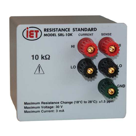
Figure 1-1: SRL Series Resistance Standard The SRL series units are available in values ranging from 1 mΩ to 2 TΩ, with custom values available, to satisfy any need. They are built with precision resistors and use no adjustable resistors of any kind. -
Page 10: Chapter 2 Specifi Cations
SRL Series Chapter 2 SPECIFICATIONS For convenience to the user, the pertinent specifi cations are given in an OPERATION GUIDE, shown in Figures 2-1 and 2-2, affi xed to the case of the instrument. SPECIFICATIONS Accuracy and other specifi cations:... - Page 11 SRL Series Stability per Max Resistance Nominal Model Adjustment to Max Applied Power Typical change year (max Change 18-28°C Terminals Value Number Nominal at 1 kHz change) from 23 °C 0 ppm change* 1 ppm change** 3 ppm change** 1 mΩ...
-
Page 12: Chapter 3 Operation
> 190 kW and <100 MW 3.2 Connections Values > 190 kΩ and <100 MΩ have two insulated, The SRL series has three diff erent types of connec- low thermal emf binding posts for two-terminal mea- tions listed below. surements as shown in Figure 3-2. The third binding 3.2.1 Connections for values... -
Page 13: Connections For Values ≥100 Mω
SRL Series 3.2.3 Connections for values 3.3 Thermal emf Considerations ³100 MW High-quality, gold-plated, tellurium-copper binding posts serve to minimize the thermal emf eff ects which Values ≥100 MΩ have two insulated, low thermal would artifi cially refl ect a change in dc resistance emf binding posts for two-terminal measurements as measurements. -
Page 14: Temperature Coeffi Cient Constants
0°C to 40°C to retain its accuracy within the specifi ed limits. 3.6 Shipping and Handling The SRL Series should not be exposed to any excessive shock or temperature extremes. The option SRC-100, a lightweight transit case capable of storing two SRL units, is recommended for shipping or transporting the models. -
Page 15: Chapter 4 Maintenance
4.1 Maintainability and Reliability 4.3.1 Calibration Interval It is possible to maintain SRL units indefi nitely. They The recommended SRL Series calibration interval is are reliable due to their closed, rugged design and twelve (12) months. sealed resistors. The units are resistant to electro-... -
Page 16: Required Equipment
Not Shown SRL-*-Res SRL resistor assembly for the required values with traceable cali- Replace * with nominal resistance value brations, such as the following standards available from IET Labs Table 4-1: Replaceable Parts List • SR-102 100 Ω • SR-103 1 kΩ...
Need help?
Do you have a question about the SRL Series and is the answer not in the manual?
Questions and answers