Table of Contents
Advertisement
Advertisement
Table of Contents

Related Manuals for Siemens Healthcare MULTIX Impact C


Summary of Contents for Siemens Healthcare MULTIX Impact C
- Page 1 MULTIX Impact C Operator Manual VA21 siemens-healthineers.com...
- Page 2 WARNING consists of the following elements: • Information about the nature of a hazardous situation • Consequences of not avoiding a hazardous situation • Methods of avoiding a hazardous situation Operator Manual MULTIX Impact C | VA21 Print No. XPB2-180G.620.20.03.02...
-
Page 3: Table Of Contents
Equipment safety measures 2.3.1 Protection against electric shock 2.3.2 Electromagnetic compatibility (EMC) 2.3.3 Safety-relevant parts subject to wear 2.3.4 Product service life 2.3.5 Mechanical safety 2.3.6 Combination with other products/components 2.3.7 Disposal Operator Manual MULTIX Impact C | VA21 Print No. XPB2-180G.620.20.03.02... - Page 4 Directions for moving and rotating the tube 4.3.2 Directions for moving 4.3.3 Directions for rotating 4.3.4 Rotating the collimator 4.3.5 Positioning the 3D overhead support with tube unit 4.3.6 Tube tracking Operator Manual MULTIX Impact C | VA21 Print No. XPB2-180G.620.20.03.02...
- Page 5 Positioning very heavy patients 5.2.6 Tube unit position 5.2.7 Manual SID 5.2.8 Detector pulled-out Positioning the patient at the wall stand 5.3.1 Hygiene 5.3.2 Radiation protection 5.3.3 Wireless detector 5.3.4 Grid Operator Manual MULTIX Impact C | VA21 Print No. XPB2-180G.620.20.03.02...
- Page 6 Equipment with accessories 6.1.2 Proper use of the product 6.1.3 Safety 6.1.4 Orientation Description 6.2.1 Trolley UM mobile patient table 6.2.2 Patient positioning mattress 6.2.3 Paper roll holder 6.2.4 Hand grip strip Operator Manual MULTIX Impact C | VA21 Print No. XPB2-180G.620.20.03.02...
- Page 7 Guidance and manufacturer's declaration - electromagnetic emissions 7.3.2 Guidelines and manufacturer's declaration - electromagnetic immunity 7.3.3 Recommended separation distance between portable and mobile RF communications equipment and the system 7.3.4 RF transmitters Glossary Index Operator Manual MULTIX Impact C | VA21 Print No. XPB2-180G.620.20.03.02...
-
Page 8: Introduction
MULTIX Impact C is not intended for mammography. MULTIX Impact C uses digital detectors for generating diagnostic images by converting X- rays into image signals. MULTIX Impact C is also designed to be used with conventional film/screen or Computed Radiography (CR) cassettes. -
Page 9: Side Effects
1.1.10 Minimum requirements concerning hardware The MULTIX Impact C system is being delivered, installed, and connected to the IT environment as a complete and functioning system by our service organization. Operator Manual MULTIX Impact C | VA21... -
Page 10: Network Characteristics
1 Introduction 1.1.11 IT network characteristics MULTIX Impact C may only be run in an environment approved or authorized by the manufacturer. The system may not be operated in public networks without firewalls or isolation. Refer to the “MULTIX Impact C Security White Paper and MDS Form”. -
Page 11: Information About This Operator Manual
To improve readability, your complete Operator Manual has been broken down into several individual Operator Manuals with thematically distinct content: • Operator Manual - MULTIX Impact C system • Operator Manual - MULTIX Impact C imaging system 1.3.1 Area of application This Operator Manual is valid for the following product: •... -
Page 12: Operator Manuals On The Internet
Any resemblance to names of real persons and institutions is entirely coincidental. All parameters and images shown in this Operator Manual are examples. Only the parameters displayed on your system are relevant. The MULTIX Impact C may be shown with expanded equipment or with optional accessories in some figures. Operator Manual MULTIX Impact C | VA21 Print No. -
Page 13: Gender Inclusivity
Values in pictures of the software user interface, have no clinical meaning. Only set the values preset in the exam sets provided or the values recommended by experienced application specialists. Operator Manual MULTIX Impact C | VA21 Print No. XPB2-180G.620.20.03.02... -
Page 14: System Safety
Operator Manual. It must be read carefully prior to starting up the MULTIX Impact C system. Application training is supplied with the equipment according to the hand-over contract. - Page 15 • Safety check for technical construction at least every two years Regulations in the USA and Canada Corresponding to the Medical Device Directive in the EU, MULTIX Impact C complies in the U.S.A. and Canada with the applicable standards. Federal law stipulates that this system may only be sold to a physician or by order of a physician.
-
Page 16: Explosion Protection
In the event of a fire, shut down the entire system immediately, that is, disconnect the system from the main power supply. 1 Press the emergency SHUTDOWN button or actuate the main or disconnecting switch. 2 Use a CO fire extinguisher. use water! Operator Manual MULTIX Impact C | VA21 Print No. XPB2-180G.620.20.03.02... -
Page 17: Information About The Software
• Devices shall be secured with physical locking cables or securely locked away; • The system shall lock down automatically or terminate the session after exceeding a reasonable defined idle time limit; Operator Manual MULTIX Impact C | VA21 Print No. XPB2-180G.620.20.03.02... - Page 18 Healthineers SVM service to monitor security vulnerabilities that may be found in future; • Siemens Healthineers will analyze vulnerability notifications from SVM in a timely manner and take appropriate measures according to their severity; Operator Manual MULTIX Impact C | VA21 Print No. XPB2-180G.620.20.03.02...
- Page 19 Public License (GPL), GNU Lesser General Public License (LGPL), or another open source license that requires source code, the corresponding code is available in the system. Warranty regarding the further use of software from third-party providers: Operator Manual MULTIX Impact C | VA21 Print No. XPB2-180G.620.20.03.02...
-
Page 20: Security Statement
Before the system is used for examinations, the user must ensure that all safety-relevant devices function correctly and that the system is ready for operation. Important functional tests and checks must be made at certain time intervals. ( Page 88 Daily checks) Operator Manual MULTIX Impact C | VA21 Print No. XPB2-180G.620.20.03.02... -
Page 21: Maintenance Plan
Prior to the first system startup, we recommend that you name a staff member who will be responsible for ensuring that routine checks and preventive inspection and maintenance work are performed. This employee has to archive all certificates. Operator Manual MULTIX Impact C | VA21 Print No. XPB2-180G.620.20.03.02... - Page 22 Protection of patient and • Measurement of ground wire resistance personnel against elec‐ • Device leakage current measurement tric shocks • Patient leakage current measurement of the complete system per national regulations Operator Manual MULTIX Impact C | VA21 Print No. XPB2-180G.620.20.03.02...
- Page 23 The purpose of preventive maintenance is to reduce unforeseen failures to a minimum. Thus the prerequisites for the system to meet the assured characteristics in the long term are created. Operator Manual MULTIX Impact C | VA21 Print No. XPB2-180G.620.20.03.02...
- Page 24 If there are differences, preventive measures must be taken or repairs performed, whenever is appropriate. Maintenance interval: 24 months for the entire system Listing of work steps to be performed: Operator Manual MULTIX Impact C | VA21 Print No. XPB2-180G.620.20.03.02...
- Page 25 * DHHS and country-specific regulations must be observed † Depending on the system configuration Replacement of safety- Safety-relevant parts which are subject to wear must be replaced in periodic intervals relevant parts subject to wear Operator Manual MULTIX Impact C | VA21 Print No. XPB2-180G.620.20.03.02...
-
Page 26: Installation, Repair Or Modifications
If you require additional information, please contact the qualified people specified by the manufacturer. Replacement You can replace the following parts if necessary once the system has been switched off: Operator Manual MULTIX Impact C | VA21 Print No. XPB2-180G.620.20.03.02... -
Page 27: Error Messages And Status Indicators
◆ Use the provided hand grips to move ceiling-suspended parts. ◆ Whenever this is not possible, pay special attention to all crush zones on the column especially those involving the hands or fingers. Operator Manual MULTIX Impact C | VA21 Print No. XPB2-180G.620.20.03.02... - Page 28 • Shut down your system and call Siemens Healthineers Service. Collision protection The MULTIX Impact C has a collision control device comprising all motor driven moving components like patient table and wall stand. Operator Manual MULTIX Impact C | VA21...
- Page 29 All system motor drives are shut down and movements are stopped immediately. Motorized movement can only be continued when STOP is canceled. Radiation is not interrupted, and can be released again even without canceling STOP. Operator Manual MULTIX Impact C | VA21 Print No. XPB2-180G.620.20.03.02...
- Page 30 In case of a system failure, press the emergency STOP button and unlock it again. The system is reinitialized. Where are the emergency STOP buttons? You find the emergency STOP buttons in the following locations: STOP On the table Operator Manual MULTIX Impact C | VA21 Print No. XPB2-180G.620.20.03.02...
- Page 31 Consequences: • All unit movements are interrupted. • Radiation is turned off. • The current system program is interrupted. Operator Manual MULTIX Impact C | VA21 Print No. XPB2-180G.620.20.03.02...
- Page 32 2 If the stop function does not respond normally, immediately activate an emergency shutdown to turn off the entire system. If this happens, you may not continue to use the system. Contact the Siemens Healthineers Customer Service. Operator Manual MULTIX Impact C | VA21 Print No. XPB2-180G.620.20.03.02...
-
Page 33: Danger Zones / Danger Points
4 If it was not possible to switch on the system or if the patient has collapsed, remove the patient immediately. For more details on the UPS, refer to ( Page 83 UPS (for the imaging system)) 2.2.2 Danger zones / danger points Danger points Operator Manual MULTIX Impact C | VA21 Print No. XPB2-180G.620.20.03.02... - Page 34 Above figure on the right shows a particular patient positioning that is not allowed because of the potential hazards when lowering the patient table. Please pay more attention to this warning sign placed on the foot end and head end of the table. Operator Manual MULTIX Impact C | VA21 Print No. XPB2-180G.620.20.03.02...
- Page 35 ◆ Do not move the table while a patient is seated near the table. System will stop when collision is detected, but there is still a risk of injury for the patient! ◆ Move the patient away from the table first. X-ray tube support Operator Manual MULTIX Impact C | VA21 Print No. XPB2-180G.620.20.03.02...
- Page 36 2 System Safety Wall stand Wallstand with pulled out detector tray Operator Manual MULTIX Impact C | VA21 Print No. XPB2-180G.620.20.03.02...
- Page 37 Pay special attention to the mentioned possibilities of crushing between moving parts and their guide openings. Make sure during the examination that the patient does not hold on to the edges of the patient table under any circumstances. Operator Manual MULTIX Impact C | VA21 Print No. XPB2-180G.620.20.03.02...
-
Page 38: Safety During Patient Examination
◆ Use other positioning aids for immobilizing weak or very unstable patients. Correct image orientation - patient orientation It is the responsibility of the operator to ensure correct image orientation on the monitor or film. Operator Manual MULTIX Impact C | VA21 Print No. XPB2-180G.620.20.03.02... - Page 39 Prerequisites for diagnosis and treatment planning The MULTIX Impact C imaging system software has been designed and tested for use in diagnosis and treatment planning based on digital radiographic X-ray images and series. To ensure that the imaging system produces monitor images suitable for these purposes, the monitor must meet certain criteria for image quality.
- Page 40 Use of the full-field light localizer CAUTION Photobiological effect of ultraviolet radiation Eye injury ◆ Do not look into the light beam for longer than 15 seconds. ◆ Always keep enough distance to the collimator. Operator Manual MULTIX Impact C | VA21 Print No. XPB2-180G.620.20.03.02...
-
Page 41: Radiation Protection
2 System Safety 2.2.4 Radiation protection The X-ray equipment MULTIX Impact C with radiation protection complies with IEC 60601-1-3 :2013, IEC 60601-2-54:2018. Mode of operation: Continuous operation with intermittent loading Important information The automatic format collimation system for acquisition helps reduce the radiation dose to the patient and examiner considerably. -
Page 42: Equipment Safety Measures
◆ Press the nearest emergency STOP button. Equipment safety measures 2.3.1 Protection against electric shock To avoid the risk of electric shock, a protective conductor must be implemented when connecting this device to mains power. Operator Manual MULTIX Impact C | VA21 Print No. XPB2-180G.620.20.03.02... -
Page 43: Electromagnetic Compatibility (Emc)
Radio interference from the system affects nearby equipment Risk of malfunction of nearby equipment. ◆ Reorient or relocate the equipment or system or shield its location. ◆ Test the operation of the equipment in its new location. Operator Manual MULTIX Impact C | VA21 Print No. XPB2-180G.620.20.03.02... -
Page 44: Safety-Relevant Parts Subject To Wear
Example of incorrect use A patient with a maximum weight sitting at the end of a fully extended tabletop. Operator Manual MULTIX Impact C | VA21 Print No. XPB2-180G.620.20.03.02... - Page 45 Movement without intentional activation of control elements. Risk of collision, risk of injury to patient or operator, risk of damage to the system. ◆ If movement does not stop, press the nearest emergency STOP button. Operator Manual MULTIX Impact C | VA21 Print No. XPB2-180G.620.20.03.02...
- Page 46 We can provide you with these warning signs. The Siemens Healthineers Uptime Service will also attach them to additionally installed components on request. Operator Manual MULTIX Impact C | VA21 Print No. XPB2-180G.620.20.03.02...
-
Page 47: Combination With Other Products/Components
IEC standards. Example: IEC 60950-1 for Information Technology Equipment and IEC 60601-1 for Medical Equipment. Furthermore all configurations shall comply with the valid version of the system standard IEC 60601-1. Operator Manual MULTIX Impact C | VA21 Print No. XPB2-180G.620.20.03.02... -
Page 48: Disposal
Siemens Healthineers customer service or your Siemens Healthineers regional office. 2.3.8 Cleaning and disinfection ( Page 49 Important general information) ( Page 50 Cleaning and disinfection process) ( Page 51 Special cleaning information) Operator Manual MULTIX Impact C | VA21 Print No. XPB2-180G.620.20.03.02... - Page 49 ◆ Make sure that no liquids are used at the top of the generator cabinet. ◆ Clean the generator cabinet covers very carefully, making sure that no liquid seeps into the cabinet. Operator Manual MULTIX Impact C | VA21 Print No. XPB2-180G.620.20.03.02...
- Page 50 Use wipes only as long as they leave a continuous liquid film on the surface. If blood is to be wiped off, discard the wipe and use a new one to continue the cleaning and disinfection procedure. Operator Manual MULTIX Impact C | VA21 Print No. XPB2-180G.620.20.03.02...
- Page 51 ◆ Remove the battery from the portable detector before cleaning the detector. ◆ Check that the detector is waterproof before immersing it (symbol on detector ◆ The battery can be wiped off but it is not waterproof. Operator Manual MULTIX Impact C | VA21 Print No. XPB2-180G.620.20.03.02...
- Page 52 2 Dry it with a soft cotton cloth. 3 Remove immediately any contamination, for example, contrast medium stains. Liquid-crystal displays (LCD) Liquid-crystal displays (LCD) are very sensitive to mechanical damage. Operator Manual MULTIX Impact C | VA21 Print No. XPB2-180G.620.20.03.02...
- Page 53 Their concentration in the air must not exceed the statutorily defined limits. Follow the manufacturers' instructions for use of these products. Sterilization The system does not require sterilization. Operator Manual MULTIX Impact C | VA21 Print No. XPB2-180G.620.20.03.02...
-
Page 54: System Overview
• For free exposures the MAX wi-D and Core XL can be equipped with a clip-on grid. 3.1.1 Application capabilities A MULTIX Impact C system may be used for projection of radiographic examinations of both adults and children (removable scattered radiation grid). • On the... -
Page 55: System Configurations
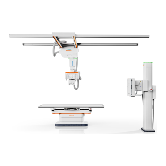
– Bucky wall stand and patient table to be used with one MAX wi-D Basic system 3.2.1 System overview in the examination room (1) MULTIX Impact C ceiling support with control panel, tube assembly, TUI (Touch User Interface) and collimator (2) Patient table (optional) (3) Bucky wall stand... -
Page 56: System Overview In The Control Room
Operate the touch screen (optional) with one dry and clean finger. For further information refer to the Imaging System Operator Manual. Operator Manual MULTIX Impact C | VA21 Print No. XPB2-180G.620.20.03.02... -
Page 57: Generator On/Off Console
Risk of undesired X-ray exposure due to wrong parameters ◆ Only suitably qualified personnel should use the system. ◆ Check the radiation parameters before releasing X-ray. ◆ Pay special attention to the exposure index (EXI). Operator Manual MULTIX Impact C | VA21 Print No. XPB2-180G.620.20.03.02... -
Page 58: Unit Overview
3.2.5 Unit overview • Patient table ( Page 72 Patient table) • Ceiling-mounted tube support ( Page 59 Ceiling-mounted tube support) • Wall stand ( Page 75 Wall stand) Operator Manual MULTIX Impact C | VA21 Print No. XPB2-180G.620.20.03.02... -
Page 59: Ceiling-Mounted Tube Support
(4) Handles with buttons Use the handles if you want to bring the tube unit manually into another position (vertical, longitudinal, transverse or rotation). (5) Multileaf collimator (ACSS) (6) Collimator control panel Operator Manual MULTIX Impact C | VA21 Print No. XPB2-180G.620.20.03.02... -
Page 60: Touch User Interface (Tui)
Example of landscape orientation (left) and portrait orientation (right) Layout Example (1) Patient information field (2) Control field (3) Movement button indicators (4) System status and information field Press the TUI with one finger. Operator Manual MULTIX Impact C | VA21 Print No. XPB2-180G.620.20.03.02... - Page 61 Tube rotation about the horizontal axis Floating movement up and down Motorized movement up Motorized movement down Longitudinal movement Longitudinal movement is in lock position. Transverse movement Transverse movement is in lock position. Operator Manual MULTIX Impact C | VA21 Print No. XPB2-180G.620.20.03.02...
- Page 62 (1) Basic tab (2) More tab (3) Organ program selection There are several basic types of buttons on the TUI. Abbreviation Type Explanation Push button Starts an action The action terminates itself. Operator Manual MULTIX Impact C | VA21 Print No. XPB2-180G.620.20.03.02...
- Page 63 Icon Short description Small/thin patient Medium patient Large/thick patient Workplace selection The selected workplace is displayed with an icon. Icon Short description Patient table Wall stand Free exposure Cassette exposure Operator Manual MULTIX Impact C | VA21 Print No. XPB2-180G.620.20.03.02...
- Page 64 Tracking function can be deactivated in "lost" state as well. (red) Top alignment Icon Short description Disabled: Preconditions are not fully fulfilled. Not pressed: center-aligned Press the centering button to activate the center alignment. Operator Manual MULTIX Impact C | VA21 Print No. XPB2-180G.620.20.03.02...
- Page 65 Software stops at -90°; 0°; +90° are turned on for tube unit rotation around the horizontal axis. Generator functions Icon Short description kV value selection ms value selection mAs value selection Operator Manual MULTIX Impact C | VA21 Print No. XPB2-180G.620.20.03.02...
- Page 66 Collimator size selection SID adjustment for free exposures System status and information field System status Icon Short description Status: Ready Status: not Ready Error messages display with the warning symbol. Operator Manual MULTIX Impact C | VA21 Print No. XPB2-180G.620.20.03.02...
- Page 67 The grid information is highlighted in yellow when the actual grid status does not match the setting in the organ program. Tube position Icon Short description SID in cm or inch Tube rotation angle RHA Operator Manual MULTIX Impact C | VA21 Print No. XPB2-180G.620.20.03.02...
-
Page 68: Multileaf Collimator
(3) Button for full-field light localizer and laser line light localizer Switches off automatically after a preset time (configurable) (4) Tape measure for SID setting (cm and inch) (5) Accessory rails with locking spring Operator Manual MULTIX Impact C | VA21 Print No. XPB2-180G.620.20.03.02... - Page 69 ◆ Do not exert any force on the multileaf collimator or its rails when inserting the accessory or auxiliary device. ◆ Check that the accessory is firmly anchored in the collimator rails. Operator Manual MULTIX Impact C | VA21 Print No. XPB2-180G.620.20.03.02...
- Page 70 (4) Camera (optional) Laser line light localizer The laser line light localizer projects the axis mark for longitudinal centering, which is aligned with the centering mark on the receptor. (1a) (1a) Operator Manual MULTIX Impact C | VA21 Print No. XPB2-180G.620.20.03.02...
- Page 71 2 To switch it off press the button again. The full field light localizer can also be switched off automatically by an internal time switch. (The internal time switch can be set by Siemens Healthineers service.) Operator Manual MULTIX Impact C | VA21 Print No. XPB2-180G.620.20.03.02...
-
Page 72: Patient Table
• Exposures in the region of the chest, of the spine, of thorax, lungs and abdomen as well as of the extremities are possible. 3.4.2 Overview The patient table can be used with a MAX wi-D or a Core XL. Operator Manual MULTIX Impact C | VA21 Print No. XPB2-180G.620.20.03.02... -
Page 73: Brake Knob
1 Pull the brake knob (5) to release the brake of the detector tray. 2 Let go of the brake knob in the desired position. The brakes now hold the detector tray in position. Operator Manual MULTIX Impact C | VA21 Print No. XPB2-180G.620.20.03.02... -
Page 74: Detector Tray With Wireless Detector
Emergency STOP push button It interrupts all motor driven system movements. STOP For more details, please refer to ( Page 14 System Safety). 3.4.6 Foot kick switches in the table base Standard functions Operator Manual MULTIX Impact C | VA21 Print No. XPB2-180G.620.20.03.02... -
Page 75: Wall Stand
• The wall stand has a centering function Fully automatic centering of X-ray tube on middle of detector or its upper edge • The wall stand can be mounted on the floor. Operator Manual MULTIX Impact C | VA21 Print No. XPB2-180G.620.20.03.02... -
Page 76: Application
Button for centering tube to detector Button for tube/detector tracking function with LED indicator Button for manual vertical movement (10) Button for unlocking the tilt mechanism (11) Degree of tilting angle Operator Manual MULTIX Impact C | VA21 Print No. XPB2-180G.620.20.03.02... -
Page 77: Front Panel Markings
The wireless detector is part of a digital image acquisition chain in an overall radiological system. It features a portable equipment designed for mobile applications. The communication is managed through a WiFi interface. Operator Manual MULTIX Impact C | VA21 Print No. XPB2-180G.620.20.03.02... - Page 78 Battery getting low tor not connected to an Access Point) LED orange - blinking slow Error state or switching ON n.a. n.a. LED orange - blinking fast n.a. n.a. Battery low Operator Manual MULTIX Impact C | VA21 Print No. XPB2-180G.620.20.03.02...
-
Page 79: Status And System Messages
LED green - blinking (once) System in exposure n.a. n.a. 3.6.2 Status and system messages In the following situations, the battery will probably be empty or the voltage will be too low: Operator Manual MULTIX Impact C | VA21 Print No. XPB2-180G.620.20.03.02... - Page 80 • The wireless detector has been accidentally left outside one of the charging locations for too long, for example over night. • The wireless detector is outside the room. Proceed as indicated in the system messages to solve the problem. Operator Manual MULTIX Impact C | VA21 Print No. XPB2-180G.620.20.03.02...
-
Page 81: System Operation
4 System Operation 4 System Operation On-Off The MULTIX Impact C system may be in one of the following operating status: • Off All the components of the system and the imaging station are turned off except for the detectors which remain in standby mode. -
Page 82: Switching On After Power Failure Or After An Emergency Shutdown Switch Is Activated
If you do so, problems may occur. 1 Press the OFF button on the console. The MULTIX Impact C system and the imaging system automatically shut down. If the ON button is pressed again within 10 seconds (configurable by Siemens Healthineers Customer Service), only the MULTIX Impact C system shuts down, not the imaging system. -
Page 83: Rebooting The System
3 Wait for power to return or start emergency power. 4 Restart the system. Description of UPS The UPS has a five-button graphical LCD. It provides useful information about the UPS itself, load status, events, measurements and settings. Operator Manual MULTIX Impact C | VA21 Print No. XPB2-180G.620.20.03.02... - Page 84 As default, or after 5 minutes of inactivity, the LCD displays the screen saver. The backlight LCD automatically dims after 10 minutes of inactivity. Press any button to restore the screen. The following table describes the status information provided by the UPS: Operator Manual MULTIX Impact C | VA21 Print No. XPB2-180G.620.20.03.02...
- Page 85 The UPS front panel display changes status to “UPS starting...”. 4 Check the UPS front panel display for active alarms or notices. Resolve any active alarms before continuing. ( Page 87 Troubleshooting) Operator Manual MULTIX Impact C | VA21 Print No. XPB2-180G.620.20.03.02...
- Page 86 • The connected devices continue to be supplied by the UPS when AC input power is no longer available. The necessary energy is provided by the battery. • The indicators illuminate solid. • The audio alarm beeps every 10 seconds. Operator Manual MULTIX Impact C | VA21 Print No. XPB2-180G.620.20.03.02...
- Page 87 Set the contact back to its normal position and press Remote power OFF, the RPO contact button to restart. has been activated to shutdown the UPS and now prevents restart. Operator Manual MULTIX Impact C | VA21 Print No. XPB2-180G.620.20.03.02...
-
Page 88: Functional And Safety Check
STOP button during the movement. The movement concerned must stop immediately. 3 Then unlock the button turning it clockwise. All system movements are possible again. Operator Manual MULTIX Impact C | VA21 Print No. XPB2-180G.620.20.03.02... - Page 89 Check the center position of radiation unit and wall stand with the light localizer and and centering/collimation check the collimation. Light on ◆ Press this button at the multileaf collimator. The light beam for collimation appears (time limited). Operator Manual MULTIX Impact C | VA21 Print No. XPB2-180G.620.20.03.02...
- Page 90 Risk of unnecessary radiation exposure ◆ Press the SHUTDOWN button to switch off the whole system. ◆ If no cause can be found, contact Siemens Healthineers Service and discontinue use of the system. Operator Manual MULTIX Impact C | VA21 Print No. XPB2-180G.620.20.03.02...
-
Page 91: Monthly Checks
2 Close the collimator on the tube assembly to a format of 10 cm x 10 cm. 3 Place a lead rubber apron, folded four times, in the beam path as a cover. 4 Release an exposure and keep the exposure switch pressed down. Operator Manual MULTIX Impact C | VA21 Print No. XPB2-180G.620.20.03.02... -
Page 92: Checks Concerning Radiology
2 Convert the result into units of [µGy x m²] and compare it with the value displayed. 3 In case of inconsistent DAP values, call service. Operator Manual MULTIX Impact C | VA21 Print No. XPB2-180G.620.20.03.02... -
Page 93: Preparation And Movements Of The Overhead Support
The X-ray tube unit can be rotated in the following directions: • about the horizontal axis (RHA) • about the vertical axis (RVA) 4.3.4 Rotating the collimator For more detailed information refer to Operator Manual MULTIX Impact C | VA21 Print No. XPB2-180G.620.20.03.02... -
Page 94: Positioning The 3D Overhead Support With Tube Unit
• Floating movement in X-, Y- and Z-direction • Floating movement in X-, and Y-direction • Floating movement in Z-direction • With or without detent functioning in X- and Y-direction Operator Manual MULTIX Impact C | VA21 Print No. XPB2-180G.620.20.03.02... - Page 95 115 cm, 150 cm, 180 cm and 300 cm for Ortho acquisition). Rotating the tube unit (RHA/RVA) The tube unit (with multileaf collimator) can be rotated manually about two axes: Operator Manual MULTIX Impact C | VA21 Print No. XPB2-180G.620.20.03.02...
- Page 96 Always check the alignment of the tube unit with the light localizer. CAUTION Rotation of tube Risk of crushing ◆ Pay special attention to all crushing hazards between the system's moving parts and their guide openings. Operator Manual MULTIX Impact C | VA21 Print No. XPB2-180G.620.20.03.02...
-
Page 97: Tube Tracking
The detector unit stops movement when it reaches the required position or the button for tube movement has been released. Operator Manual MULTIX Impact C | VA21 Print No. XPB2-180G.620.20.03.02... -
Page 98: Sid Tracking
✓ A detector is inserted in the closed tray of the patient table. ✓ Tube unit is positioned above the table. ✓ Tube unit RHA angle is 0° ± 3°. ✓ Tube unit RVA angle is 0°. ✓ SID ≥ 90 cm Operator Manual MULTIX Impact C | VA21 Print No. XPB2-180G.620.20.03.02... -
Page 99: Deactivation Of A Tracking Control
The collimator can be rotated out of the stop position 0°. The maximum rotation in both direction is ±45° by using the Siemens Healthineers tube flange. Assure that the rotation is not limited by the wiring harness. Operator Manual MULTIX Impact C | VA21 Print No. XPB2-180G.620.20.03.02... -
Page 100: Preparation And Movements Of The Patient Table
◆ Remove any objects or accessories, for example injector or infusion stand, from the collision area. ◆ Make sure you are standing outside the dangerous area. ◆ Always watch the patient when performing system movements. Operator Manual MULTIX Impact C | VA21 Print No. XPB2-180G.620.20.03.02... -
Page 101: Collision Protection
Moving the table up ◆ Actuate the second foot kick switch from the right in the table base. – or – Actuate the middle foot switch (optional) for table up movement. Operator Manual MULTIX Impact C | VA21 Print No. XPB2-180G.620.20.03.02... -
Page 102: Positioning The Tabletop
2 Push the tabletop manually into the required position. Putting a strain on the extended tabletop may activate the collision control device. 4.4.4 Inserting wireless detector 1 Push the tabletop away from you as far as possible. Operator Manual MULTIX Impact C | VA21 Print No. XPB2-180G.620.20.03.02... - Page 103 Push the detector tray back completely, or else the detector is not loaded in the detector tray. Be careful not to damage the detector when sliding it into the tray as the tray does not have a mechanism to absorb the shock. Operator Manual MULTIX Impact C | VA21 Print No. XPB2-180G.620.20.03.02...
-
Page 104: Positioning The Detector Tray
✓ If the software stop fucntion is configured, activate the function and rotate the tube unit to the software detent at 0°. ( Page 96 Rotation about horizontal axis (RHA)) Operator Manual MULTIX Impact C | VA21 Print No. XPB2-180G.620.20.03.02... -
Page 105: Scattered Radiation Grid
The responsibility for selecting and inserting the scattered radiation grid to be used for an exposure lies with the examiner. The intended SID is color-coded on each table grid using the following color scheme: Operator Manual MULTIX Impact C | VA21 Print No. XPB2-180G.620.20.03.02... - Page 106 ◆ The expected grid status (inserted, removed) is indicated on the imaging system. ◆ Manually remove or insert the grid from or into the detector tray as required before making the X-ray exposure. Operator Manual MULTIX Impact C | VA21 Print No. XPB2-180G.620.20.03.02...
- Page 107 1 Push the tabletop away from you. 2 Press the locking lever at the left side of the grip and, keeping it straight, pull the grid out towards the front. 3 Remove the grid. Operator Manual MULTIX Impact C | VA21 Print No. XPB2-180G.620.20.03.02...
-
Page 108: Preparation And Movements Of The Wall Stand
CAUTION Loose patient hand grips on the wall stand Mechanical or personal injury ◆ Check that patient hand grips are in right position when moving detector up or down. Operator Manual MULTIX Impact C | VA21 Print No. XPB2-180G.620.20.03.02... -
Page 109: Detector Unit Movements
◆ Press the button for the manual vertical movement and move the detector unit up or down to the required working height. When moving down the detector unit, be careful not to hit the ground. Operator Manual MULTIX Impact C | VA21 Print No. XPB2-180G.620.20.03.02... -
Page 110: Inserting The Detector Into The Wall Stand
Inserting the detector into the wall stand (with wireless mobile detector only) 1 Move the detector unit to a convenient working height. Vertical movement (height adjustment) of the detector unit Operator Manual MULTIX Impact C | VA21 Print No. XPB2-180G.620.20.03.02... - Page 111 5 Carefully and slowly slide in the detector tray with the detector. Be careful not to damage the detector when sliding it into the tray as the tray does not have a mechanism to absorb the shock. Operator Manual MULTIX Impact C | VA21 Print No. XPB2-180G.620.20.03.02...
-
Page 112: Removing The Detector
Only the same type of grid can be shared from other system. CAUTION Grid is dropped or not handled properly Risk of invisible damage and impaired image quality ◆ Handle the grid with special care. Operator Manual MULTIX Impact C | VA21 Print No. XPB2-180G.620.20.03.02... - Page 113 (SID) on which the grid is focused. 1 Hold the grid vertically, labels facing the tube unit. The label with the tube symbol on the grid must point toward the tube unit. Operator Manual MULTIX Impact C | VA21 Print No. XPB2-180G.620.20.03.02...
-
Page 114: Positioning The Tube Unit Automatically
Activate the tube tracking function by pressing the button on the wall stand. The LED indicator is on. ( Page 97 Tube tracking) – or – Move the tube unit to the vertical center position with the help of the light localizer. Operator Manual MULTIX Impact C | VA21 Print No. XPB2-180G.620.20.03.02... -
Page 115: Centering The Tube Unit In Vertical Direction
In such situation, protect the detector with a single use plastic bag. Operator Manual MULTIX Impact C | VA21 Print No. XPB2-180G.620.20.03.02... -
Page 116: Recommendations
Detector temperature out of range X-ray without diagnostic value ◆ Check the temperature icon on the display regularly. EMC compliance Portable and mobile RF communication equipment can affect the detector operation. Operator Manual MULTIX Impact C | VA21 Print No. XPB2-180G.620.20.03.02... -
Page 117: Notes On Handling The Detector
Be sure to use the detector unit on a flat place so it will not bend. Otherwise, the detector may be damaged. hit the detector surface in any way. Operator Manual MULTIX Impact C | VA21 Print No. XPB2-180G.620.20.03.02... - Page 118 Burns or heat injuries ◆ Pay attention to the warning messages pertaining to detector surface temperature. ◆ Remove the detector from contact with the patient if the surface temperature exceeds 41°C (106°F). Operator Manual MULTIX Impact C | VA21 Print No. XPB2-180G.620.20.03.02...
- Page 119 (> 70 cm). The shock sensor is not visible on the MAX wi-D. However, the shock details can be accessed in the Detector Overview. ( Page 126 FD management) Operator Manual MULTIX Impact C | VA21 Print No. XPB2-180G.620.20.03.02...
-
Page 120: Maintenance
◆ Connect the portable detector to a loading port when it is not in use. ◆ Consider purchasing the battery loading station and additional batteries if portable detector availability is important. Operator Manual MULTIX Impact C | VA21 Print No. XPB2-180G.620.20.03.02... - Page 121 (frequency) can be selected by the site for use. However, the available channels depend on legal regulations and requirements of the country with the installed system (wireless detector of MULTIX Impact C). The wireless connection is encrypted. For this the widely used and very secure WPA2 is applied.
-
Page 122: Battery Change (Max Wi-D)
In case a WLAN-network is present in your work environment, the channels of the access points can be detected in the room where MULTIX Impact C will be installed. The frequencies in use (channels if you have WLAN) should be communicated to the Siemens Healthineers project manager. - Page 123 6 Close the locking system of the battery and push down the latch to ensure no protrusion of the locking system. When the battery is inserted correctly, the detector starts automatically. 7 Before using the detector, wait until all LEDs are green. Operator Manual MULTIX Impact C | VA21 Print No. XPB2-180G.620.20.03.02...
-
Page 124: Battery Change (Core Xl)
3 Orientate the charged battery in the correct position: battery connector (1) facing the device connector (2). 4 Slide battery into the recess area of the device. 5 Push down the battery in the recess area. Operator Manual MULTIX Impact C | VA21 Print No. XPB2-180G.620.20.03.02... -
Page 125: Charging The Battery Of The Detector
When the system is switched off, make sure that the main power is on and put the detector in the closed detector tray, otherwise the battery will run down. Operator Manual MULTIX Impact C | VA21 Print No. XPB2-180G.620.20.03.02... -
Page 126: Fd Management
◆ Check that detector identification on the detector label matches the detector identification shown on the user interface. ◆ Check that the green ready light on the correct detector is lighted before releasing radiation. Operator Manual MULTIX Impact C | VA21 Print No. XPB2-180G.620.20.03.02... -
Page 127: Attaching The Detector
◆ Charge the detector battery or replace it by a fully charged battery. ◆ It takes approximately 10 minutes to finish the firmware upgrade. ◆ Start the attachment again. Operator Manual MULTIX Impact C | VA21 Print No. XPB2-180G.620.20.03.02... -
Page 128: Detaching The Detector
A detector calibration must be performed after the MAX wi-D has been exchanged. Only one wireless detector can be connected to the MULTIX Impact C at the same time. CAUTION Exposure on a wireless detector that is connected to another system Image data will be lost. -
Page 129: Emergency Operation
Portable detector not available for use ◆ Maintain procedures and equipment so that cassettes can be used in place of the portable detector for free exposures if necessary. Operator Manual MULTIX Impact C | VA21 Print No. XPB2-180G.620.20.03.02... -
Page 130: Examination
6 Let the patient get on or off the table only in the central area. CAUTION Incorrect positioning of the patient. Risk of injury ◆ Ensure correct positioning of the patient. This applies in particular when using the different accessory parts. Operator Manual MULTIX Impact C | VA21 Print No. XPB2-180G.620.20.03.02... -
Page 131: Positioning The Patient On The Table
◆ Do not allow the patient to sit at the head end of the table. ◆ Call Siemens Healthineers Service and have the tabletop checked immediately if there is a possibility that it might have been damaged. 1 Center the tabletop. Operator Manual MULTIX Impact C | VA21 Print No. XPB2-180G.620.20.03.02... -
Page 132: Tube Unit Position
2 If necessary, cover the tabletop with fresh paper. 5.3.2 Radiation protection ◆ Apply the necessary radiation protection to the patient. 5.3.3 Wireless detector ◆ Insert the wireless mobile detector in the detector tray. Operator Manual MULTIX Impact C | VA21 Print No. XPB2-180G.620.20.03.02... -
Page 133: Grid
• Three-field templates, which can be introduced into the accessory rails of the multileaf collimator for projecting the IONTOMAT dominants onto the object are available for this purpose. ( Page 207 Three-field template, set) Operator Manual MULTIX Impact C | VA21 Print No. XPB2-180G.620.20.03.02... -
Page 134: Performing Iontomat Automatic Exposure Control
◆ If several measuring chambers have been selected simultaneously, check the selection carefully. Additional Cu filter There are four possibilities of selecting internal additional Cu filters for the automatic collimator: • 0.0 mm (no) Cu • 0.1 mm Cu Operator Manual MULTIX Impact C | VA21 Print No. XPB2-180G.620.20.03.02... -
Page 135: Selecting Additional Filters
Collimation close to the object reduces the scattered radiation and thus improves image quality. The radiation exposure to the patient is also reduced. To protect the patient from unnecessary radiation, always check the collimation position with the light localizer. Operator Manual MULTIX Impact C | VA21 Print No. XPB2-180G.620.20.03.02... -
Page 136: Switching On And Off Of The Light Localizer
The internal time switch can be set by service: 5 s to 118 s Switching on/off manually You can switch the light localizer on or off at any time independent of automatic switching on and off. ◆ Press the button on the collimator. Operator Manual MULTIX Impact C | VA21 Print No. XPB2-180G.620.20.03.02... -
Page 137: Collimation
5.7.2 Collimation / Automatic Collimation Size Sensing MULTIX Impact C supports ACSS (Automatic Collimation Size Sensing). ACSS limits the maximum opening of the collimator to the borders of the selected detector in the table and Bucky wall stand. ACSS is indicated by the letters ACSS in the collimator display. -
Page 138: Restoring The Last Collimation
Exposures onto the patient table ( Page 139 Vertical projection onto the patient table) ( Page 140 Vertical projection onto the pulled-out detector) ( Page 141 Oblique projection onto the patient table) Operator Manual MULTIX Impact C | VA21 Print No. XPB2-180G.620.20.03.02... -
Page 139: Vertical Projection Onto The Patient Table
Switch the light localizer on the multileaf collimator on if required: ◆ Press the button, if necessary. Positioning the patient Push the patient with the floating tabletop into the required position: ◆ Actuate the foot kick switch or foot switch. Operator Manual MULTIX Impact C | VA21 Print No. XPB2-180G.620.20.03.02... -
Page 140: Vertical Projection Onto The Pulled-Out Detector
(0°): Loosen the brakes with the push buttons on the control panel or with the buttons on the handles and position the tube unit. Operator Manual MULTIX Impact C | VA21 Print No. XPB2-180G.620.20.03.02... -
Page 141: Oblique Projection Onto The Patient Table
(RHA) is displayed in degrees in the display of the TUI. Pay special attention in the diagnosis to distortions of the image geometry due to the oblique projection! Operator Manual MULTIX Impact C | VA21 Print No. XPB2-180G.620.20.03.02... -
Page 142: Exposures Onto The Wall Stand
Manual movement of the tube unit to the required position: 1 Position the tube unit manually as required for the exposure using the movement buttons on the control panel or with the buttons on the handles. Operator Manual MULTIX Impact C | VA21 Print No. XPB2-180G.620.20.03.02... -
Page 143: Auto Thorax Collimation
Manual movement of the tube unit to the required position: 1 Position the tube unit manually as required for the exposure using the movement buttons on the control panel or with the buttons on the handles. Operator Manual MULTIX Impact C | VA21 Print No. XPB2-180G.620.20.03.02... -
Page 144: Oblique Projection Onto The Wall Stand
4 Release the brakes with the push buttons on the control panel or with the buttons on the handles and position the tube unit. angle of the rotation about the horizontal axis (RHA) is displayed in degrees in the display of the TUI. Operator Manual MULTIX Impact C | VA21 Print No. XPB2-180G.620.20.03.02... -
Page 145: Free Exposure Onto The Wireless Detector
Wrong angles displayed, tube not aligned to detector Radiation not usable ◆ After the system has been positioned, do a final check to make sure that the tube, anatomy and detector are properly aligned before releasing radiation. Operator Manual MULTIX Impact C | VA21 Print No. XPB2-180G.620.20.03.02... -
Page 146: Preparations
1 Press the button on the tube unit control panel. – or – Actuate the table height adjustment. Measure the SID with the tape measure: Distance up to the detector. Operator Manual MULTIX Impact C | VA21 Print No. XPB2-180G.620.20.03.02... -
Page 147: Positioning For Vertical Projection
3 Release the brakes with the push buttons on the control panel or with the buttons on the handles and position the tube unit. 4 Make the exposure. Operator Manual MULTIX Impact C | VA21 Print No. XPB2-180G.620.20.03.02... -
Page 148: Ortho Operation
The X-ray tube unit is positioned in the middle of the Ortho cover range. When an Ortho sequence is started, the detector moves automatically to the different positions (up to 4). The tube follows the detector, by tilting itself accordingly. Operator Manual MULTIX Impact C | VA21 Print No. XPB2-180G.620.20.03.02... -
Page 149: Organ Program For Ortho
If the series acquisition is interrupted, the whole sequence must be started again from the beginning! ( Page 149 Organ program for Ortho) ✓ An Ortho organ program is selected. ✓ The collimator must be in the 0° lock-in-position. Operator Manual MULTIX Impact C | VA21 Print No. XPB2-180G.620.20.03.02... - Page 150 ◆ Always use the Ortho stand if you are doing an Ortho study. ( Page 173 Multipurpose / Ortho stand) 1 Carefully position the Ortho stand as close as possible to the detector tray. Operator Manual MULTIX Impact C | VA21 Print No. XPB2-180G.620.20.03.02...
- Page 151 If a constant deviation is observed, contact the Siemens Healthineers service to adjust the offset. Adjusting the ROI with start and end position in the examination room ✓ SmartOrtho is configured. ✓ ( Page 149 Preparing Ortho) Operator Manual MULTIX Impact C | VA21 Print No. XPB2-180G.620.20.03.02...
- Page 152 • Redefine the ROI. • Use the additional removable platform on the Ortho stand when performing Ortho acquisition on the wall stand. ( Page 173 Multipurpose / Ortho stand) Operator Manual MULTIX Impact C | VA21 Print No. XPB2-180G.620.20.03.02...
- Page 153 ✓ The X-ray tube unit is positioned for Ortho. ✓ TOD has been set correctly. 1 Click the button on the imaging system. The Ortho acquisition range (ROI) is shown with an orange frame on the imaging system. Operator Manual MULTIX Impact C | VA21 Print No. XPB2-180G.620.20.03.02...
- Page 154 ✓ The X-ray tube unit is positioned for Ortho. ✓ TOD has been set correctly. ◆ Click the button on the imaging system. The ROI is automatically detected and shown with a blue frame on the imaging system. Operator Manual MULTIX Impact C | VA21 Print No. XPB2-180G.620.20.03.02...
-
Page 155: Releasing The Ortho Exposures
4 Press the acquisition push-button fully down and keep it pressed until all the acquisitions are finished. The first position is acquired and displayed. The system moves to the next acquisition position. Operator Manual MULTIX Impact C | VA21 Print No. XPB2-180G.620.20.03.02... -
Page 156: Pediatric Use: Summary
12 year old or a 5th percentile U.S. adult female. Exposure to ionizing radiation is of particular concern in pediatric patients because: Operator Manual MULTIX Impact C | VA21 Print No. XPB2-180G.620.20.03.02... -
Page 157: Use Of Anti-Scatter Grid
The status of the selected chamber is displayed at the imaging system as well as at the touch user interface. Operator Manual MULTIX Impact C | VA21 Print No. XPB2-180G.620.20.03.02... -
Page 158: Specific Organ Programs For Pediatric Examinations
Gently® Digital Radiography Safety Checklist, Safety Steps to Do and Verify for Your Pediatric Patient". http://www.imagegently.org/ 5.12.6 Pediatric positioning aids Positioning aids are available that support a safe examination with small patients. These aids are described in Register Accessories and Auxiliary Devices. Operator Manual MULTIX Impact C | VA21 Print No. XPB2-180G.620.20.03.02... -
Page 159: Accessories And Auxiliary Devices
◆ Make sure that accessory parts are attached firmly by pulling and pushing them. ◆ Follow the instructions in the Operator Manual. ◆ Observe the information regarding storage and maximum weight when using the accessories. Operator Manual MULTIX Impact C | VA21 Print No. XPB2-180G.620.20.03.02... -
Page 160: Safety
Lead radiation protection can drop on the patient Risk of patient injury ◆ Avoid any collisions with the radiation protection when moving the system. ◆ Make sure that the radiation protection is securely fastened. Operator Manual MULTIX Impact C | VA21 Print No. XPB2-180G.620.20.03.02... -
Page 161: Orientation
As a patient supporting device of the X-ray imaging system, Trolley UM mobile patient table can facilitate X-ray imaging of the recumbent patient, for instance the examination of stomach and lower limbs. Operator Manual MULTIX Impact C | VA21 Print No. XPB2-180G.620.20.03.02... - Page 162 When the patient is moving onto or leaving the patient table, the brake pedal must stay locked. Besides, give assistance to the patient, otherwise the table might slide to create hazard. Operator Manual MULTIX Impact C | VA21 Print No. XPB2-180G.620.20.03.02...
- Page 163 The X-ray imaging system must be operated by trained and qualified personnel. In addition, make sure to follow the requirements of relevant laws and regulations during the operating process. Operator Manual MULTIX Impact C | VA21 Print No. XPB2-180G.620.20.03.02...
- Page 164 ◆ Do not use normal grid in the mobile patient table. Use the clip-on grid instead. Cleaning and disinfection Before cleaning and disinfecting the equipment, make sure no liquid can seep into the interior of the equipment. Operator Manual MULTIX Impact C | VA21 Print No. XPB2-180G.620.20.03.02...
-
Page 165: Patient Positioning Mattress
Atmospheric pressure 700 hPa to 1060 hPa 6.2.2 Patient positioning mattress Application The mattress is used for comfortable patient positioning and is attached to the protection strip of the tabletop. Operator Manual MULTIX Impact C | VA21 Print No. XPB2-180G.620.20.03.02... -
Page 166: Paper Roll Holder
◆ Ensure that hand grips are tightened prior to use. ◆ Make sure that the patient uses the hand grips during system movements or when turning over. ◆ Use other positioning aids for immobilizing weak or very unstable patients. Operator Manual MULTIX Impact C | VA21 Print No. XPB2-180G.620.20.03.02... - Page 167 2 Position the hand grip strip from below at the accessory rail as shown in above figure. 3 Lift it up and turn it down (see following figure) We recommend placing the hand grip strip on the far side of the user. Operator Manual MULTIX Impact C | VA21 Print No. XPB2-180G.620.20.03.02...
-
Page 168: Hand Grip, Lateral
◆ Ensure that hand grips are tightened prior to use. ◆ Make sure that the patient uses the hand grips during system movements or when turning over. ◆ Use other positioning aids for immobilizing weak or very unstable patients. Operator Manual MULTIX Impact C | VA21 Print No. XPB2-180G.620.20.03.02... - Page 169 2 Insert the hand grip into the groove of the accessory rail and slide it into the desired position. 3 Tighten the hand grip by turning it clockwise. Please make sure that the hang grips are securely fastened. Operator Manual MULTIX Impact C | VA21 Print No. XPB2-180G.620.20.03.02...
-
Page 170: Overhead Patient Hand Grip
◆ Please pay special attention when patients use the grip! ◆ The maximum load on the overhead patient handgrip must not exceed the stated value (see label). Operator Manual MULTIX Impact C | VA21 Print No. XPB2-180G.620.20.03.02... - Page 171 ◆ The maximum load on the overhead patient handgrip is 25 kg. ◆ When moving or removing the overhead patient hand grip, pull it vertically upwards out of its holder. Operator Manual MULTIX Impact C | VA21 Print No. XPB2-180G.620.20.03.02...
-
Page 172: Babix Holder
The BABIX holder is now ready to hook up the BABIX. 2 Check the BABIX holder (1) for firm attachment at the support arm (2) by pulling or pushing it. Operator Manual MULTIX Impact C | VA21 Print No. XPB2-180G.620.20.03.02... -
Page 173: Multipurpose / Ortho Stand
Accessory overbalances and tips over causing damage to system or injury of persons. ◆ Do not ride or allow anyone else to stand, sit or ride on wheeled accessories while they are being rolled. Operator Manual MULTIX Impact C | VA21 Print No. XPB2-180G.620.20.03.02... - Page 174 (4) Additional removable platform for smaller patients (for example children) and for examinations of the lower extremities (5) Brake pedals (on both sides) (6) Patient platform (with positioning indentations for additional platform and swivel stool) Operator Manual MULTIX Impact C | VA21 Print No. XPB2-180G.620.20.03.02...
- Page 175 CAUTION Mounting the Ortho stand Patient can slip or fall down ◆ Position the patient hand grips at the lowest possible position when the patient is mounting or dismounting. Operator Manual MULTIX Impact C | VA21 Print No. XPB2-180G.620.20.03.02...
- Page 176 Removing the handgrips 1 To remove the hand rips when used as stretch grip, just turn the locking screws counterclockwise and remove the handgrips upwards from the guide rails. Operator Manual MULTIX Impact C | VA21 Print No. XPB2-180G.620.20.03.02...
- Page 177 To lock the brakes push the pedal down towards the symbol of the closed padlock (1). To release the brakes push the pedal down towards the symbol of the open padlock (2). Operator Manual MULTIX Impact C | VA21 Print No. XPB2-180G.620.20.03.02...
- Page 178 (3) Screw to fix swivel stool in a certain position on the rails (4) Rails for longitudinal movement (5) Fixing bolt for the attachment of the stool on the patient platform Operator Manual MULTIX Impact C | VA21 Print No. XPB2-180G.620.20.03.02...
- Page 179 1 Attach the holding device to one of the guide rails (2) and fix it by turning the locking screw (A) clockwise. 2 To move the holder vertically, release the locking screw (A). Operator Manual MULTIX Impact C | VA21 Print No. XPB2-180G.620.20.03.02...
- Page 180 5 Position the ruler in the slot and fix it with the fixing clamp as shown above right. BABIX holder The BABIX holder is used to fasten the BABIX during pediatric examinations of small children. Operator Manual MULTIX Impact C | VA21 Print No. XPB2-180G.620.20.03.02...
- Page 181 The BABIX holder can only be mounted on the right guide rail at the top. ◆ Slide the support arm (2) with the BABIX holder (3) from above on the guide rail (4) and fix it with the cap screw (1). Operator Manual MULTIX Impact C | VA21 Print No. XPB2-180G.620.20.03.02...
- Page 182 Babix holder overload Risk of damage to of the babix holder and injury of the patient ◆ Do not load the BABIX holder at the point of suspension with more than 10kg. Operator Manual MULTIX Impact C | VA21 Print No. XPB2-180G.620.20.03.02...
- Page 183 1 Lift the fixing device (1). 2 Place the detector on the lower holder. 3 Slide the fixing device downward. 4 Ensure the detector is seated properly in the holder. Operator Manual MULTIX Impact C | VA21 Print No. XPB2-180G.620.20.03.02...
- Page 184 DIN EN 60601-1-3 Location of labels All labels displayed in the operator manuals are examples only and may differ from the labels attached to the system and components. Operator Manual MULTIX Impact C | VA21 Print No. XPB2-180G.620.20.03.02...
- Page 185 6 Accessories and Auxiliary Devices (2)(3)(9) (10)(11) (7)(8) (4)(5)(6) (1)(2)(3) (1) Weight label (200 kg) (2) Type B equipment label (3) Refer to manual label (4) Ortho stand ID label Operator Manual MULTIX Impact C | VA21 Print No. XPB2-180G.620.20.03.02...
- Page 186 6 Accessories and Auxiliary Devices (5) China nameplate label (6) Weight label (120 kg) (7) DHHS label (8) Al equivalent label (9) Handgrip ID label (10) Weight label (30 kg) (11) Caution label Operator Manual MULTIX Impact C | VA21 Print No. XPB2-180G.620.20.03.02...
-
Page 187: Compression Belt
2 Do not use corrosive, soluble or abrasive cleaning materials for cleaning. 3 For sprayed paint, plastic and chromium alloy surface, make sure to use clean and dry soft cloth to wipe clean. Operator Manual MULTIX Impact C | VA21 Print No. XPB2-180G.620.20.03.02... - Page 188 (2) downward: tightened Tag for cap screw Intended use The compression belt is a mechanical component for X-ray exposures. It is used to quickly fix the patient on the table. Operator Manual MULTIX Impact C | VA21 Print No. XPB2-180G.620.20.03.02...
- Page 189 4 Press both tension levers (2) outward. 5 Check that the tensioning roller is firmly seated by pulling on it. 6 Press the ratchet handle (1) downward. The belt is released. Operator Manual MULTIX Impact C | VA21 Print No. XPB2-180G.620.20.03.02...
- Page 190 The compression belt unclenches. 4 Use the ratchet handle to set a lower belt tension. Removal 1 Move the patient table to the horizontal position. 2 Press the ratchet handle (1) back. Operator Manual MULTIX Impact C | VA21 Print No. XPB2-180G.620.20.03.02...
- Page 191 11 Help the patient to get off the patient table. 12 Use the cap screw (3) to roll up the belt on the tensioning roller. Technical data Dimensions Width ≤ 100 mm Operator Manual MULTIX Impact C | VA21 Print No. XPB2-180G.620.20.03.02...
- Page 192 -20°C to +70°C Relative humidity 10% to 95% rel. air humidity without con‐ densation Barometric pressure 500 hPa to 1060 hPa Aluminum equivalent ≤ 0.8 mm Al Location of labels Operator Manual MULTIX Impact C | VA21 Print No. XPB2-180G.620.20.03.02...
- Page 193 • ANSI/AAMI ES60601-1 (2005 + C1:09 + A2:10), Medical Electrical Equipment, Part 1: General Requirements for Basic Safety and Essential Performance • IEC 60601-1:1988 + A1:1991 + A2:1995 • IEC 60601-1: 2005 + A1:2012 Operator Manual MULTIX Impact C | VA21 Print No. XPB2-180G.620.20.03.02...
-
Page 194: Cassette Holder, Lateral
Minimum cassette formats 13 x 18 cm vertical or 18 cm x 24 cm horizontal. Maximum load capacity 3 kg Attachment ✓ Patient table in horizontal position. 1 Position the patient. Operator Manual MULTIX Impact C | VA21 Print No. XPB2-180G.620.20.03.02... - Page 195 2 Loosen the cap screw (2). 3 Lift the rail for height adjustment. 4 Tighten the cap screw (2). 5 Open the clamping lever (1). 6 Remove the cassette holder from the accessory rail. Operator Manual MULTIX Impact C | VA21 Print No. XPB2-180G.620.20.03.02...
-
Page 196: Cassette Holder Without Retainer
4 Ensure that the cassette is seated properly in the holder. 5 Position the cassette holder on the tabletop at the patient in the location appropriate for the examination. 6 Ensure that the cassette holder is stable. Operator Manual MULTIX Impact C | VA21 Print No. XPB2-180G.620.20.03.02... -
Page 197: Mobile Detector Holder
CAUTION The detector holder is not securely fastened. Injury of persons or damage to the detector or holder ◆ Make sure the detector holder is securely fastened. Operator Manual MULTIX Impact C | VA21 Print No. XPB2-180G.620.20.03.02... -
Page 198: Detector Holder, Lateral
The detector holder can be attached to either of the two lateral accessory rails of the patient table. 1 Take the detector holder with both hands (high weight!) and insert it into the groove of the accessory rail. Operator Manual MULTIX Impact C | VA21 Print No. XPB2-180G.620.20.03.02... - Page 199 1 Take the detector out of the detector holder from above. detector holder 2 Place the detector in a safe location. 3 Dismantle the detector holder with both hands from the lateral accessory rail of the patient table. Operator Manual MULTIX Impact C | VA21 Print No. XPB2-180G.620.20.03.02...
-
Page 200: Clip-On Grids
(3) Clip-on grid ✓ Detector front must face the backside of the clip-on grid. 1 Put the detector with the bottom in the clip-on grid as show in above figure. Operator Manual MULTIX Impact C | VA21 Print No. XPB2-180G.620.20.03.02... -
Page 201: Fd Protector
The FD protector is a protective cover for the detector. It is used for examinations where the patient has to stand on the detector if the patient body weight exceeds 100 kg. Operator Manual MULTIX Impact C | VA21 Print No. XPB2-180G.620.20.03.02... -
Page 202: Wall Holder For Grids
This holder is used for storage of exchangeable grids or cassette trays. You can mount it to the wall. 6.2.17 Compensation filters Application Absorption compensation for acquisitions of: • Pelvis • Foot • Infant skull • Adult skull • T-spine, L-spine • Shoulder Operator Manual MULTIX Impact C | VA21 Print No. XPB2-180G.620.20.03.02... - Page 203 Compensation filter for infant skull and compensation filter for adult skull BWS, lateral BWS, lateral BWS, a.p. Compensation filter for thoracic spine, lat. and compensation filter for thoracic or lumbar spine, lat. Operator Manual MULTIX Impact C | VA21 Print No. XPB2-180G.620.20.03.02...
- Page 204 The safety spring in the left rail is pushed beside in this case. 2 Push the filter up to the stop. Operator Manual MULTIX Impact C | VA21 Print No. XPB2-180G.620.20.03.02...
- Page 205 The safety spring in the left rail has to be pushed beside in this case. 2 Keep filter secured in the holder. Please be careful when handling the compensation filters. They are thin, scratch- sensitive, and may become unusable due to rough handling. Operator Manual MULTIX Impact C | VA21 Print No. XPB2-180G.620.20.03.02...
-
Page 206: Filter Holder For Eight Filters
Storing the compensation filter ◆ Place the filter in a free compartment of the wall holder, turn the filter so that you can read the designation on the filter reading normally from above. Operator Manual MULTIX Impact C | VA21 Print No. XPB2-180G.620.20.03.02... -
Page 207: Three-Field Template, Set
1 Push the locking lever on the left accessory rail to the left. 2 Pull the template out of the accessory rails. The locking lever on the accessory rail springs to the right. Operator Manual MULTIX Impact C | VA21 Print No. XPB2-180G.620.20.03.02... -
Page 208: Wireless Remote Control Console
The operator must assure that other wireless devices in the 2.4-GHz ISM band are not operated in the vicinity of appr. 5 m around the MULTIX Impact C system. System movements can interrupt sporadically. Please observe and verify normal operation of the Wireless Remote Control Console prior to using it. - Page 209 The remote control is active in a range of approx. 7 m around the tube stand, where the receiver is mounted. If the remote control is in a wider range of the table, it may lose contact with the receiver. It then turns into an inactive mode. Operator Manual MULTIX Impact C | VA21 Print No. XPB2-180G.620.20.03.02...
- Page 210 • LED off: No operation button is being pressed or the dead-man sensor is not activated. • LED on: An operation button is being pressed and meanwhile the dead-man sensor is activated. Operator Manual MULTIX Impact C | VA21 Print No. XPB2-180G.620.20.03.02...
- Page 211 • Closing the collimator in vertical direction - or - • Moving the tube unit down in vertical direction • Closing the collimator in horizontal direction • Opening the collimator in horizontal direction Operator Manual MULTIX Impact C | VA21 Print No. XPB2-180G.620.20.03.02...
- Page 212 To enable the tracking function, the preconditions must be fully fulfilled. ( Page 97 Tube tracking) Charging We recommend charging the batteries every day after deployment using the USB charging cable. USB charging cable Operator Manual MULTIX Impact C | VA21 Print No. XPB2-180G.620.20.03.02...
-
Page 213: Foot Switch
CISPR 11 Compliance: Group 2 FCC 47 CFR 15, RED, SRRC The deployment of Wireless Remote Control in combina‐ tion with MULTIX Impact C wi-D changes the classifica‐ tion of MULTIX Impact C wi-D from compliance group 1 to compliance group 2. Marking signs The Wireless Remote Control is marked with a colored sign of different shape. -
Page 214: Battery Charger (Max Wi-D)
The battery charger is designed to insert a battery in only one direction. 1 Insert the battery into the charger as shown above. 2 Pay attention to the alignment identification (1) on the battery and the charging slot (see above). Operator Manual MULTIX Impact C | VA21 Print No. XPB2-180G.620.20.03.02... - Page 215 No battery inserted Battery not inserted correctly. 1 Remove battery and insert it again correctly. 2 If problem remains, check that connectors are not damaged or battery is not faulty. Operator Manual MULTIX Impact C | VA21 Print No. XPB2-180G.620.20.03.02...
-
Page 216: Battery Charger (Core Xl)
3 Slide battery into the recess area of the device. Once the battery is in place correctly, the bottom green LED starts blinking. Charging a fully discharged battery will take a maximum of 4 hours. Operator Manual MULTIX Impact C | VA21 Print No. XPB2-180G.620.20.03.02... -
Page 217: Wall Charger
2 Make sure that the handle of the detector points up and the charging contacts of the detector face the wall to permit the charging procedure to start. Operator Manual MULTIX Impact C | VA21 Print No. XPB2-180G.620.20.03.02... -
Page 218: Barcode Scanner
3 If the scanner still does not function properly, contact your Siemens Healthineers Customer Service. Operator Manual MULTIX Impact C | VA21 Print No. XPB2-180G.620.20.03.02... -
Page 219: Intercom System In Control Room
Power ON or OFF button Listening (loudspeaker) ON or OFF button (10) Speaking (microphone) ON or OFF button 6.2.27 Smart Remote Control Refer to the Smart Remote Control Operator Manual. Operator Manual MULTIX Impact C | VA21 Print No. XPB2-180G.620.20.03.02... -
Page 220: Technical Description
7.1.1 Labels on the ceiling-mounted tube support (1) System ID label The following symbols are contained in the labels, if applicable: Medical device Operator Manual MULTIX Impact C | VA21 Print No. XPB2-180G.620.20.03.02... - Page 221 Those individual components may be devices in themselves. (2) China nameplate label (3) Unit revision label (4) Refer to manual label (5) Australia label Operator Manual MULTIX Impact C | VA21 Print No. XPB2-180G.620.20.03.02...
- Page 222 (8) Warning label for ionizing radiation for deliveries to China (9) SGS label (10) Label for deliveries to Singapore (11) Brazil label (12) MoH label for deliveries to Ministry of health in Saudi Arab Operator Manual MULTIX Impact C | VA21 Print No. XPB2-180G.620.20.03.02...
- Page 223 (13) EAC label (This label is for Eurasian Economic Union (EEU) with EAC declaration done.) (14) DHHS label for deliveries to USA (15) Malaysia label (16) Upgrade kit label (17) Swiss Representative label (Indicates the authorized representative in Switzerland) Operator Manual MULTIX Impact C | VA21 Print No. XPB2-180G.620.20.03.02...
-
Page 224: Labels On The Tube Unit With Multileaf Collimator
Labels on the tube unit with multileaf collimator (1) Refer to manual label (2) DAP label for deliveries to Germany and Austria (3) Tube 2nd set of labels Only for deliveries to China Operator Manual MULTIX Impact C | VA21 Print No. XPB2-180G.620.20.03.02... -
Page 225: Labels On The Wall Stand
(4) Laser radiation label (5) Color coding label (only when WRCC or Smart Remote Control is configured) 7.1.3 Labels on the wall stand (1)(2) (1)-(6) STOP (10) (6)(7) (1) Wall stand ID label Operator Manual MULTIX Impact C | VA21 Print No. XPB2-180G.620.20.03.02... - Page 226 (2) Unit revision label (3) DHHS label (4) Detector 2nd set of label (5) Core static ID label (6) 25 kg label (7) Type B label (8) Iontomat label (only the right label) Operator Manual MULTIX Impact C | VA21 Print No. XPB2-180G.620.20.03.02...
-
Page 227: Labels On The Patient Table
(5)(6) (1) Wireless detector position labels For Core XL, only one label is pasted on the table (left) and wall stand (right). (2) Iontomat label for table with wireless detector Operator Manual MULTIX Impact C | VA21 Print No. XPB2-180G.620.20.03.02... -
Page 228: Labels On The Generator On/Off Console
(3) Warning label of crush leg (4) Anti-grip label (5) Patient table ID label (6) Unit revision label (7) Iontomat label for table with fixed detector 7.1.5 Labels on the generator ON/OFF console Operator Manual MULTIX Impact C | VA21 Print No. XPB2-180G.620.20.03.02... -
Page 229: Labels On The Generator Cover
(1) Radiation emission warning label for deliveries to USA (2) DHHS label for deliveries to USA 7.1.6 Labels on the generator cover (1) -(5) (1) Caution label (2) Refer to manual label Operator Manual MULTIX Impact C | VA21 Print No. XPB2-180G.620.20.03.02... -
Page 230: Technical Data
Ambient conditions (operation): Temperature range +10°C to +35°C Examination room Relative humidity 20% to 75%, non-condensing Barometric pressure 700 hPa to 1060 hPa Height ≤ 3000 m above sea level Operator Manual MULTIX Impact C | VA21 Print No. XPB2-180G.620.20.03.02... - Page 231 < 0.5 mm Al DAP chamber Dose area product is measured by DAP meter at the collimator Tolerance of DAP values ± 35% AEC chambers AEC chambers attenuation equivalent 0.7 mm Al Operator Manual MULTIX Impact C | VA21 Print No. XPB2-180G.620.20.03.02...
-
Page 232: Components
• With table tray for Core static: 426 mm x 426 mm Bucky wall stand Travel range (central beam to floor) From 31.5 cm to 175 cm Detector unit Tiltable from -20° to +90° withdetent at 0° and +90° Operator Manual MULTIX Impact C | VA21 Print No. XPB2-180G.620.20.03.02... - Page 233 = 300 W) 33 kW/78 kW (150/180Hz) Nominal anode input power (thermal anode reference out‐ 29 kW/73 kW (50/60Hz) put = 0 W) 45 kW/107 kW (150/180Hz) Anode angle 12° Operator Manual MULTIX Impact C | VA21 Print No. XPB2-180G.620.20.03.02...
- Page 234 42% at 2 lp/mm 29% at 3 lp/mm 19% at Nyquist MTF in % (RQA5) (IEC 62220) 63% at 1 lp/mm 35% at 2 lp/mm 19% at 3 lp/mm 12% at Nyquist Operator Manual MULTIX Impact C | VA21 Print No. XPB2-180G.620.20.03.02...
- Page 235 < 3 s preview; < 7 s full image DQE in %; 2µGy (RQA5), (IEC 62220) 80% at 0.05 lp/mm 65% at 1 lp/mm 53% at 2 lp/mm 34% at 3 lp/mm 21% at Nyquist Operator Manual MULTIX Impact C | VA21 Print No. XPB2-180G.620.20.03.02...
- Page 236 < 3 s preview; < 5 s full image DQE in %; 2µGy (RQA5), (IEC 62220) 80% at 0.05 lp/mm 65% at 1 lp/mm 53% at 2 lp/mm 34% at 3 lp/mm 21% at Nyquist Operator Manual MULTIX Impact C | VA21 Print No. XPB2-180G.620.20.03.02...
- Page 237 • 80 kW : 100 kV, 80 mAs, (800 mA) Max. tube current and voltage • 55 kW: 68 kV at 800 mA • 65 kW: 81 kV at 800 mA • 80 kW: 80 kV at 1,000 mA Operator Manual MULTIX Impact C | VA21 Print No. XPB2-180G.620.20.03.02...
- Page 238 In JPG, BMP, or TIFF format via USB/DVD/CD-R Documentation • DICOM Print • Virtual Film Sheet DICOM Worklist, MPPS Data exchange via HIS/RIS Paper printing Printing of lists and images to a net‐ work paper printer Operator Manual MULTIX Impact C | VA21 Print No. XPB2-180G.620.20.03.02...
-
Page 239: Network Information
(5) DICOM TCP Port 104 (6) Switch on customer site (7) Any RIS or HIS or PACS MULTIX Impact C uses the Windows firewall to restrict access. The following ports need to be opened in the hospital network firewall: Application... - Page 240 Precautions to take if the use location is near (e.g. less than 1.5 km from) AM, FM or TV broadcast antennas. The essential performance of this equipment is defined in particular medical electrical equipment standard, such as IEC 60601-2-43, IEC 60601-2-54. Operator Manual MULTIX Impact C | VA21 Print No. XPB2-180G.620.20.03.02...
-
Page 241: Guidance And Manufacturer's Declaration - Electromagnetic Emissions
The same as IEC 60601 test level Mains power quality should to line be that of a typical commer‐ IEC 61000-4-5 cial or hospital environment. ± 0.5 kV, ± 1, ± 2 kV line to ground Operator Manual MULTIX Impact C | VA21 Print No. XPB2-180G.620.20.03.02... - Page 242 Conducted RF d=1.2 √P IEC 61000-4-6 150 kHz-80 MHz 6 V; in ISM bands 6 V; in ISM bands between 150 kHz and 80 MHz 80% AM at 1 kHz Operator Manual MULTIX Impact C | VA21 Print No. XPB2-180G.620.20.03.02...
-
Page 243: Recommended Separation Distance Between Portable And Mobile Rf Communications Equipment And The System
Separation distance according to frequency of transmitter [m] transmitter [W] 150 kHz to 80 MHz 80 MHz to 800 MHz 800 MHz to 2.7 GHz d=1.2 √P d=1.2 √P d=2.3 √P 0.01 0.12 0.12 0.23 Operator Manual MULTIX Impact C | VA21 Print No. XPB2-180G.620.20.03.02... -
Page 244: Rf Transmitters
The mobile communications other than WIFI or BLUETOOTH is not intended to be used. The user must follow the regional regulation and RF use restriction of the patient to whom special care must be taken. Operator Manual MULTIX Impact C | VA21 Print No. XPB2-180G.620.20.03.02... -
Page 245: Glossary
Organ Program Rotation about the horizontal axis Region of Interest Rotation about the vertical axis Source Image Distance Table-Object Distance Touch User Interface Uninterruptible Power Supply WRCC Wireless Remote Control Console Operator Manual MULTIX Impact C | VA21 Print No. XPB2-180G.620.20.03.02... -
Page 246: Index
FD protector 201 Detector 77 handling 117 Cassette holder without retainer 196 Filter holder 206 management 126 operation 206 Ceiling-mounted tube support 59 Detector calibration 128 Fire Centering safety 16 checking 89 Operator Manual MULTIX Impact C | VA21 Print No. XPB2-180G.620.20.03.02... - Page 247 IT-security 20 OEM = Original Equipment Manufacturer 19 Potential equalization 42 OFF 81 Power failure 33 ON 81 Labels Power outlet 42 ON/OFF console 57 location 220 Power supply 42 Operator Manual MULTIX Impact C | VA21 Print No. XPB2-180G.620.20.03.02...
- Page 248 Smart Virtual Ortho marking signs 213 SmartOtho 148 operating elements 211 SmartOrtho 151 operation 209 Unit movements technical data 213 safety information 27 WRCC = Wireless Remote Control Console 208 Operator Manual MULTIX Impact C | VA21 Print No. XPB2-180G.620.20.03.02...
- Page 249 Index X-ray tube support danger points 35 Operator Manual MULTIX Impact C | VA21 Print No. XPB2-180G.620.20.03.02...
- Page 250 278 Zhou Zhu Road 91052 Erlangen 91052 Erlangen 201318 Shanghai Germany Germany P.R.China Phone: +49 9131 84-0 siemens.com/healthineers Published by Siemens Healthcare GmbH / Print No. XPB2-180G.620.20.03.02 / © Siemens Healthcare GmbH, 2021-2022 Date of first issue: 2021-11 / Revision date: 2022-11...