Table of Contents
Advertisement
Quick Links
with
SERVICE AND MAINTENANCE MANUAL
REFER TO MATERIAL LIST LIT-2360
FOR SPECIFIC PARTS IDENTIFICATION
LIT2363_R6_2-2012
Printed in U.S.A.
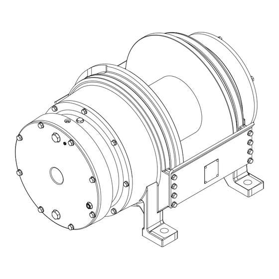
GH30B
FreeFall Attachment
(Liebherr Units Only)
P.O. BOX 547 BROKEN ARROW, OK U.S.A. 74013
PHONE (918) 251-8511 FAX (918) 259-1575
www.paccarwinch.com
1
WINCH DIVISION
© PACCAR Inc
All Rights Reserved
Advertisement
Table of Contents

Subscribe to Our Youtube Channel
Related Manuals for Paccar Winch Gearmatic GH30B


Summary of Contents for Paccar Winch Gearmatic GH30B
- Page 1 GH30B FreeFall Attachment with (Liebherr Units Only) SERVICE AND MAINTENANCE MANUAL WINCH DIVISION P.O. BOX 547 BROKEN ARROW, OK U.S.A. 74013 PHONE (918) 251-8511 FAX (918) 259-1575 REFER TO MATERIAL LIST LIT-2360 www.paccarwinch.com FOR SPECIFIC PARTS IDENTIFICATION © PACCAR Inc LIT2363_R6_2-2012 All Rights Reserved Printed in U.S.A.
-
Page 2: Table Of Contents
INTRODUCTION The following service instructions have been prepared to provide assembly, disassembly, and maintenance information for the Gearmatic Model GH30B with FreeFall option. It is suggested that before doing any work on these units, all assembly and disassembly instructions should be read an understood. Some illustrations in this manual may show details or attachments that are different from your hoist. -
Page 3: General Description
EXPLANATION OF MODEL NUMBER GH30 B - FF - SPL - 40 000 - GH30 - DESIGNATES GEARMATIC 30 SERIES HOIST FAMILY - EVOLUTIONARY DESIGNATION - FULL RELEASE FREE FALL EQUIPPED - SPECIAL ORDER DESIGNATION - TOTAL GEAR REDUCTION (40:1) - MOTOR CODE, 000 WITHOUT MOTOR, ISO = MOTOR MOUNT &... -
Page 4: Safety Recommendations
13. Do not weld on any part of the hoist without approval in failure of wire rope, hoist or boom structure. from PACCAR Winch Engineering. 28. Whenever possible, install the hoist in a location that 14. Use recommended hydraulic oil and gear lubricant. -
Page 5: General Installation
GENERAL INSTALLATION 1. The hoist must be mounted with the centerline of the CAUTION WARNING drum in a horizontal position. 2. When mounting the hoist, use SAE grade 8 (ISO class DO NOT use a control valve with any detents or latch- 10.9) capscrews or bolts and nuts using both mount- ing mechanism that would hold the control valve in an ing holes in each end plate. -
Page 6: Wire Rope Installation
WIRE ROPE INSTALLATION CAUTION WARNING THE CABLE ANCHORS ALONE ON HOISTS ARE NOT INTENDED TO HOLD RATED LOADS. Hoist loads applied directly to the wire rope anchor may cause the wire rope to pull free and result in the sudden loss of load control and cause property damage, personal injury or death. -
Page 7: Hoist Operation
If you have any questions concerning the safe operation of this hoist or the equipment it is mounted on, contact the equipment manufacturer that installed the hoist, or the PACCAR Winch Division Product Support Department at 1-918-251-8511, Monday through Friday, 0800 to 1630 hours CTZ, by fax at 1-918- 259-1575, or via the internet at www.paccarwinch.com. -
Page 8: Preventative Maintenance
PREVENTATIVE MAINTENANCE A regular program of preventive maintenance for your plan- 6. A warm-up procedure is recommended at each start- etary hoist is required to minimize the need for emergency up and is mandatory at ambient temperatures below servicing and promote safe, reliable hoist operation. +40°F (4°C). - Page 9 The gear oil should be changed whenever the ambient drum drain plug. Rotate the drum until the drain plug is at temperature changes signifi cantly and an oil from a dif- the lowest point. ferent viscosity range would be more appropriate. Our tests indicate that excessively heavy or thick gear oil may To change the gear oil, remove the drain plugs shown on contribute to intermittent brake slippage.
-
Page 10: Oil Requirements
Recommended Planetary Gear Oil Failure to use the proper type and viscosity of planetary gear oil may contribute to intermittent brake slippage which could result in property damage, severe personal injury or death. Some gear lubricants contain large amounts of EP (extreme pressure) and anti-friction additives which may contribute to brake slippage and damage to brake friction discs or seals. - Page 11 OIL SAMPLING AND ANALYSIS Proper oil sampling and analysis of the sample, is a vital Analysis part of a comprehensive preventive maintenance program. General Guide Lines Information obtained from the oil analysis is best utilized in (After approximately 250 hours of operation) conjunction with a regular program of preventive mainte- Note: The fi...
-
Page 12: Hoist Disassembly
HOIST DISASSEMBLY CAUTION The GH30B-FF weighs approximately 1650 lbs (750 kg). Make certain lifting equipment has adequate capacity. Using NOTE undersized or poorly maintained lifting equipment may result in a dropped load, property damage injury or death. DRAIN PLUGS 1. Remove the wire rope from the hoist. Drain the gear 5. - Page 13 6. Remove the three divider plates (211), and one brake plate (212). 8. Mark the tie plates to the side of the hoist to ease re- assembly. Remove the tie-plate capscrews and lock- washers and remove the tie-plates (21). Remove the sun gear shaft (5).
- Page 14 CAUTION The complete freefall assembly must be removed to service the internal parts, because the bearing support (802) cannot be removed without fi rst removing the freefall assembly at the support end-plate (3). This is done by removing the bolts and lockwashers (35 & 16). See Warning on page 15 10.
-
Page 15: Freefall Attachment Service
FREE FALL ATTACHMENT DISASSEMBLY CAUTION The GH30B freefall assembly weighs approximately 250 lb (114 kg). Make certain lifting equipment has ad- equate capacity. Using undersized or poorly maintained lifting equipment may result in a dropped load, property damage, injury or death. Refer to Winch disassembly to remove the freefall assem- bly from the winch. - Page 16 FREE FALL ATTACHMENT 4. Remove the two spacers (815), ten divider plates (814), and seven friction plates (813). Clean and Inspect 1. Thoroughly clean and inspect all parts. Check sealing surfaces on the free fall housing, bearing support, and piston. Ensure the free fall release port is clean and free of debris.
- Page 17 FREE FALL ATTACHMENT ASSEMBLY 1. Place the freefall housing (801) on a clean work sur- face with the bearing support (802) side facing up. Coat the friction plates with gear oil prior to installa- tion. 2. Place a spacer (815) in the freefall housing. The sev- en (7) friction discs and ten (10) divider plates must be installed in the proper order.
-
Page 18: Brake Cylinder Service
BRAKE CYLINDER DISASSEMBLY 1. A hydraulic press or spring compressor tool is re- quired to disassemble the brake subassembly. Place the brake subassembly on the press with the primary housing cover (201) down. Place a heavy steel bar across the large diameter of the pressure plate (210) and compress the springs until spring force is removed from the retaining ring (209). - Page 19 BRAKE CYLINDER ASSEMBLY 1. A hydraulic press or spring compressor tool is required 5. Install the spring separator (208). The spring spacer to assemble the brake subassembly. Place the brake seats on the piston. Install the springs (207) in the housing cover (201) on a clean work surface with the spring separator and space evenly.
-
Page 20: Cable Drum Service
CABLE DRUM SERVICE DISASSEMBLY ASSEMBLY Note: The capscrews used to fasten the drum fl ange to the drum barrel are different lengths for each drum 1. Stand the drum with the freefall end fl ange down. Re- fl ange. The motor end fl ange capscrews are 2 inch move the twelve capscrews (508) and lift the motor long hex heads, and the freefall end capscrews are end fl... -
Page 21: Primary Planet Carrier Service
PRIMARY PLANET CARRIER SERVICE DISASSEMBLY 1. Remove the planet gears by fi rst driving the roll pins (306) into the center of the planet gear shafts (302). 2. Use a punch to drive the roll pins from the planet gear shafts. - Page 22 PRIMARY PLANET CARRIER SERVICE ASSEMBLY 1. Install a bearing into a planet gear and place a thrust washer on each side of the gear. Position this assem- bly into an opening in the carrier. Slide a planet gear shaft through the carrier, thrust washer, bearing and remaining thrust washer.
-
Page 23: Output Planet Carrier Service
OUTPUT PLANET CARRIER SERVICE DISASSEMBLY ASSEMBLY 1. Place the output carrier on a clean work surface with the splined end up. 2. Apply a liberal coat of oil soluble grease to a thrust washer and center it on one side of a planet gear. Place the planet gear on a clean work surface with the thrust washer down. -
Page 24: Hoist Assembly
HOIST ASSEMBLY 1. Assemble Brake, Cable Drum, Freefall, and Planet 10. Install the tie-plates using the shoulder capscrews (23) Carrier subassemblies following procedures in the and lockwashers (16) and torque to 110 Lb-ft (149 subassembly section of this manual. N-m). NOTE: The shoulder of the tie plate capscrew extends 2. -
Page 25: Cross-Section
13. There are three divider plates (211) and one friction brake plate (212) in the GH30B freefall hoist. First, install two divider plates in the primary housing. Apply gear oil to the friction surface of the brake plate and place on top of the two divider plates. Then install the remaining divider plate as shown in the photograph below. -
Page 28: Compression Tooling Diagram
SPRING COMPRESSION TOOL 13.0 (330.2) .75-10 ALL THREAD ROD (20X2.5 mm) 3/4-10 NUT (20x2.5 mm) FILLET FILLET WELD WELD .75X3” BAR STOCK (20X75 mm) 10.50 (25.4) (266.7) (25.4) THREADED ROD TAP AND WELD TO .75X3” BAR STOCK BOTTOM BAR (20X75 mm) FILLET WELD 14.0... -
Page 30: Metric Conversion Chart
METRIC CONVERSION TABLE English to Metric Metric to English LINEAR inches (in.) X 25.4 = millimeters (mm) millimeters (mm) X 0.3937 = inches (in.) feet (ft.) X 0.3048 = meters (m) meters (m) X 3.281 = feet (ft.) miles (mi.) X 1.6093 = kilometers (km) kilometers (km)
Need help?
Do you have a question about the Gearmatic GH30B and is the answer not in the manual?
Questions and answers