Table of Contents
Advertisement
Quick Links
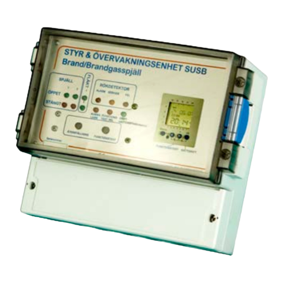
SUSB
Control and
monitoring unit
Valid from week of manufacture 40/2012.
Software version 3.0
Description
The SUSB is a control and monitoring unit
designed to control various types of fire/smoke
dampers and fans in a flexible way. The SUSB
is based on a modern powerful
microprocessor, so it can meet all the
requirements of a building installation.
General
• 8 different operating modes can be selected
• 2 damper groups, max. 4 dampers
• 2 detector groups
• 2 fan groups
• Built-in locking of fans
• Real time clock with battery backup
• Preconfigured for easy installation
• External input for central fire alarm system
• Dampers can be closed via external inputs
• Function test button
• Damper position indication
• Expansion units available
• Compact plastic case
• Rack installation
• Integrated transformer
• 24 V supply to actuator
New in Version 3.
Separate input for pressure switch on the
automatic function test of Smoke Evacuation
Fans.
The watch is now used for function tests.
___________________________________________________________________
ON Control AB, Hjortstigen 5, 507 70 GÅNGHESTER
Telephone: +46 33 25 65 70, Mobile: +46 70 625 86 00, Fax: +46 33 25 69 20
Beskrivning SUSB ver3_0 eng.doc
Maximum configuration.
Up to four actuators (dampers) can be
connected in 2 groups. The distribution
between groups can be 2+2 or 3+1. Expansion
units can be installed for an unlimited number
of dampers, although they will all be
controlled by the same function. In principle,
any number of smoke detectors can be
connected, but the number is often limited by
the difficulty in maintaining this kind of
solution. Detectors can be connected to the
SUSB via two separate loops. An external
monitoring unit can also be connected.
Installation
Designed for wall installation or DIN rail
mounting. Mounting details is needed for DIN
rail mounting.
Supply voltage
230 VAC 50 Hz 30VA. Protected with 2A at
least.
Protection class
IP65. If the unit is located outdoor it is
possible to get the enclosure in polycarbonate.
Ambient temperature
Max +30°C, min 0°C.
Weight
1,5 Kg
11/10/2012
1
Page
Advertisement
Table of Contents

Related Manuals for ON Control SUSB

Summary of Contents for ON Control SUSB
- Page 1 2+2 or 3+1. Expansion designed to control various types of fire/smoke units can be installed for an unlimited number dampers and fans in a flexible way. The SUSB of dampers, although they will all be is based on a modern powerful controlled by the same function.
- Page 2 • Fan 2. Voltage-free changeover contact Accessories max 10A / 250V. Terminal number • DIN rail mounting. 16,17,18. • Expansion unit for 4 dampers. (SUSB-E) • Expansion unit for 8 dampers. (SUSB-E8) Inputs Outputs • Smoke detector 1. Terminal DET1 +,- •...
- Page 3 Mode 2. Mode 6. (Jumper B ON) (Jumpers B and D ON) One fire zone is handled via one detector loop, Combination mode. Damper group 1 is used and up to four fire dampers in one group. for fire/smoke dampers and for locking the Detector 2, damper 2 and fan lock 2 are not ventilation system for fan 1.
-
Page 4: Installation
Fire/smoke dampers are connected as shown in The fire ventilation fans can be controlled the diagram below. from 1 or 2 outputs on the SUSB. If two fans If evacuation dampers are used, they must be are connected, they are started with a 10 connected with Ö... - Page 5 EKKX 1*4*0.5 if the distance between connected directly to the terminal. 2200 ohm, the actuator and the SUSB is less than 100 power at least 0.6W. See also the description metres. If the distance is greater, a larger area of the modes.
- Page 6 4-wire control and monitoring actuator actuator equipment, for example KSUB, SUSB and SUSB-E. It is also easy to use the connection box to create parallel connections. The box is available with or without a test button to KBOX KBOX operate dampers manually.
-
Page 7: Time-Switch
Time-switch is self-explanatory as you step through the menu. The time switch is used for automatic tests of damper and Smoke Evacuation fans. The time switch has a battery backup, which will secure approx six years operation without mains voltage. To save energy the time-switch uses a so-called sleep-mode i.e. - Page 8 2 seconds, the output of the clock will be set permanently ON or OFF. This function overrides the programmed time. Graphic of programming. Understanding and use CONTROL PANEL SUSB Fire and smoke dampers SMOKE DETECTOR DAMPER ALARM SERVICE...
-
Page 9: Operation
The patterns used to determine which of the Indicators and buttons two loops is faulty are the same as for service A Dampers alarms. Green or red LED indicates open or closed dampers respectively D Weekly timer switch The damper groups are numbered 1 and 2. The control clock is for the function test time. - Page 10 requires that clock channel 1 is not active. periphery of a ventilation system. Only OFF must appear in the clock window. The affects the ventilation system, not fire function test is limited in modes 4, 5, 6, 7 and ventilation. Only active in modes 1, 2, 8 because the fire ventilation fan does not start 3, 6 and 7.
-
Page 11: Troubleshooting
• That the electronic fuse has not tripped. If by a yellow LED on the affected detector if the detector has a service alarm function. it has, switch off the power to the SUSB for Vacuum-clean or, in the worst case, replace around 5 minutes to cool/reset. - Page 12 Disposal of old Electrical & Electronic Equipment (Applicable throughout the European Union and other European countries with separate collection programs) This symbol, found on your product or on its packaging, indicates that this product should not be treated as household waste when you wish to dispose of it.
Need help?
Do you have a question about the SUSB and is the answer not in the manual?
Questions and answers