Table of Contents
Advertisement
Quick Links
Advertisement
Chapters
Table of Contents

Related Manuals for Gesytec Easylon ISA-Bus


Summary of Contents for Gesytec Easylon ISA-Bus
- Page 1 ISA-Bus Interface User Manual Easylon ISA-Bus Interface Easylon PC/104 Interface Gesytec GmbH Pascalstr. 6 52076 Aachen, Germany Tel. + (49) 24 08 / 9 44-0 Fax + (49) 24 08 / 94 4-100 email: info@gesytec.de www.gesytec.com Doc. ID: 96A0016E01, V3.8...
- Page 2 Microsoft. Other names may be trademarks of their respective companies. The Easylon ISA-Bus Interface card and the Easylon PC/104 Interface card incorporate the MIP/P50 or NSI programs from the Echelon Corporation. The aforesaid company holds all rights relating to this software.
-
Page 3: Table Of Contents
ISA Bus Interface ....................24 Reset Procedure, System Control ................25 Block Diagram .....................25 Connector Pin Assignments .................27 3.5.1 Easylon ISA-Bus Interface ..................27 3.5.2 Easylon PC/104 Interface ..................28 3/44... - Page 4 Connecting External LEDs ..................29 Technical Specification ..................30 3.8.1 General .........................30 3.8.2 Easylon ISA-Bus Interface ..................31 3.8.3 Easylon PC/104 Interface ..................31 Electromagnetic Compatibility ................32 Programming Instructions ....................33 ...
-
Page 5: Product Information
ISA bus Interface card in PC/104 format. NOTE: In this manual both cards are generally referred to as “Interface cards”. If differ- ences between the two have to be described, they are explicitly referred to as “Easylon ISA-Bus Interface” or “Easylon PC/104 Interface”. 5/44... -
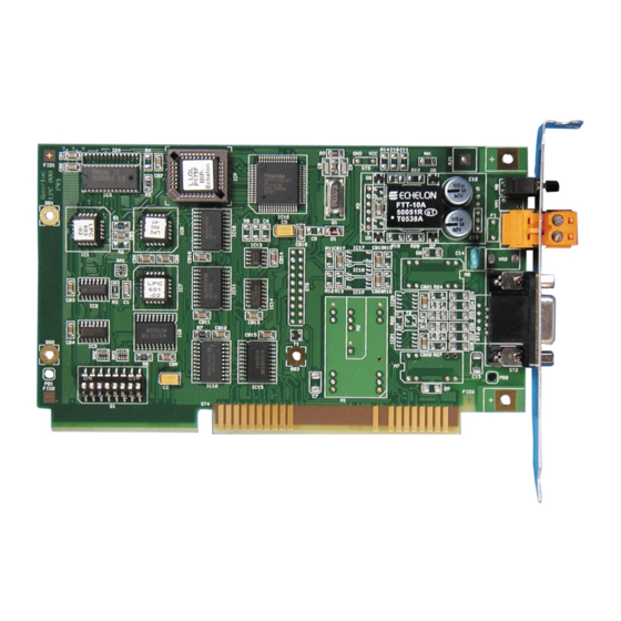
Page 6: Figure 1-1 Easylon Isa-Bus Interface
ISA-Bus Interface User Manual Product Information Figure 1-1 Easylon ISA-Bus In- terface GESYTEC L.LOLPO… (1) Service button MIP- Neuron ® Echelon ® 3150 Chip IC11 (2) Service LED (3) Screw-plug terminal (TP/XF and FTT 1 variants only) (4) 9 pin D-type connector (5) ROM with Echelon‘s MIP/P50 or NSI... -
Page 7: Variants
P.P11012 TP/XF-1250 + Watcher LPC.DA P.P10003 E/A-485 MIP/P50 LPC.DB P.P11003 E/A-485 MIP/P50 + Watcher LPC.DC P.P10013 E/A-485 LPC.DD P.P11013 E/A-485 + Watcher Table 1-1 Variants, order-codes and type identifiers for Easylon ISA-Bus Interface The Easylon Watcher has been discontinued. 7/44... -
Page 8: Table 1-2 Variants, Order-Codes And Type Identifiers For Easylon Pc/104 Interface
ISA-Bus Interface User Manual Product Information Type Code Order Code Network Interface Variants Easylon PC/104 Interface LP42.BA P.P10601 TP/XF-78 MIP/P50 LP42.BC P.P10611 TP/XF-78 LP42.CA P.P10602 TP/XF-1250 MIP/P50 LP42.CC P.P10612 TP/XF-1250 LP42.DA P.P10603 RS-485 MIP/P50 LP42.DC P.P10613 RS-485 LP42.AA P.P10604 FTT10 MIP/P50 LP42.AC P.P10614... -
Page 9: Scope Of Delivery
Firmware are alternatively MIP/P50 or NSI. While MIP is the cheaper solution offering more memory NSI will always be needed if LNS is used. The Easylon ISA-Bus Interface card is provided with a service button and LED. In the TP/XF and FTT variants, this card is equipped with two connectors, either... -
Page 10: Installation
Setting the I/O Addresses Both the Easylon ISA-Bus Interface and the Easylon PC/104 Interface are as- signed four I/O addresses on the ISA bus of the PC. The base address of this I/O range is set via DIP switches (cf. Figure 1-1, (7) and Figure 1-2, (6)). Before set- ting the base address, establish which address range is available on your comput- er in its current configuration. -
Page 11: Insertion Of The Card
Insertion of the Card Prior to inserting the interface cards read the Mounting instructions enclosed in the delivery. When inserting the Easylon ISA-Bus Interface card or the Easylon PC/104 card in your computer, please be sure to observe all the computer manu- facturer's instructions regarding the insertion of additional interface cards. -
Page 12: Installation Of The Network Driver
Furthermore there are drivers for Win- dows CCE, Linux and MS-Dos. Latest driver versions you can downloadvia the Easylon Support pages of our web site: www.gesytec.com. Installation is described in the following sections: Windows operating systems chapter 2.3.1... - Page 13 However, this may require stepping through up to 15 dialog boxes. If you are using this method anyway, please select the setup file „LpcWdm.inf“ and the „Gesytec LPC WDM Driver ISA/PC-104“ driver. One advantage you will get using this method: resource selection will be made during the installation procedure.
-
Page 14: Update
ISA-Bus Interface User Manual Installation 2.3.1.2 Update In case you want to update an existing driver start FastUpd.exe from the “Lpclpp” directory on the CD-ROM. A new version will be installed from CD within a few seconds. 2.3.1.3 Parameter Setting Certain operating conditions may require special settings for the Easylon Inter- faces. - Page 15 ISA-Bus Interface User Manual Installation Lon Adapter You can assign a name „LON1“ ... „LON9“ to the interface board, as some ap- plications may require. ATTENTION The name chosen must not be in use by any other driver. The device will not start if a name is used twice.
-
Page 16: De-Installation
This can be turned off by selecting “None”. 2.3.1.4 De-installation De-installation uses the Windows Device Manager. Select the driver „Gesytec LPCxxx“ under „LON Adapters“ with the right mouse key and choose de-install 2.3.2 Windows 95 / NT Driver This section describes the driver setup for the Easylon Interface cards for the Windows 95 and Windows NT operating systems. -
Page 17: Installation
2.3.2.2 De-installation De-installation of the drivers is done via the system control software. For this, first choose the item "Easylon ISA-Bus Interface" and then click "Insert/Delete". After the de-installation, the system has to be restarted. 2.3.3 EasyCheck – Test Utility for Windows Drivers In addition to the drivers, the test utility “EasyCheck”... -
Page 18: Windows And 16 Bit Applications
ISA-Bus Interface User Manual Installation 2.3.4 Windows and 16 Bit Applications The Windows driver for the 32 bit Windows versions also provides a 16 bit in- terface. (Unfortunately Microsoft does not support this in the 64 bit versions.) To use it, the following entry has to be made in the file „config.nt“, usually found in the windows\system32 directory: Device=%SystemRoot%\system32\ lpxdos.exe –Llpcwdm340 A more specific definition of the 32 bit LON device used is made by optional pa-... -
Page 19: Windows Ce Driver
To use an Easylon Interface card as device named LON1 with the base address 0x340 and interrupt IRQ 10 (=0x0A hex) you have to add following in the file „Lpcdrv.reg“: [HKEY_LOCAL_MACHINE\Gesytec\Lpcdrv\LON1] "IoBase" = dword:0340 "Irq" = dword:a The .reg file is provided in the Windows CE driver directory. -
Page 20: Use As Built In Driver
A main functionality of Windows CE driver support is to be able to register a driver several times. This driver will handle several devices in parallel. However, this release of the Gesytec LonWorks network driver for Windows CE does not support this mechanism! As a workaround you have to copy and rename the driver, e.g. -
Page 21: Installation
ISA-Bus Interface User Manual Installation The driver can be taken form the CD-ROM’s „DOS“ directory. There are two versions: Driver without interrupt „lpcdrv.exe“ Driver with interrupt „lpcdrv2.exe“. The driver files „lpcdrv.exe“ or „lpcdrv2.exe“ have to be copied onto the hard disk of your computer, e.g. -
Page 22: Display Of Network Drivers Installed In The Computer
LON1: ... LON9: already defined Increasing the input buffer The input and output buffers of the Easylon ISA-Bus Interface network driver are configured as byte-level FIFOs, i.e. the space requirement of a message is dependent on its length. Consequently, a buffer capacity of 2 Kbytes (default, approx. - Page 23 ISA-Bus Interface User Manual Installation /R The option /R additionally enables modification of the device number. Example: lpcdrv -r13 changes the name LON1: to LON3: If the first device number does not exist, or if the second number has al- ready been assigned to another device driver, the message Invalid or duplicate device name will appear.
-
Page 24: Technical Description
ISA-Bus Interface User Manual Technical Description Technical Description This chapter describes the ISA-Bus interface card and two generations of the Ea- sylon PC/104 Interface. The PC/104 cards can be identified by the type codes “LP4” for the old and “LP42” for the new cards. Wherever necessary these names are used to discern both. -
Page 25: Reset Procedure, System Control
Chip starts up automatically. EURON Block Diagram 9-pin D-type screw-plug terminal transceiver- service button/LED module ® Neuron memory watcher oscillator 3150 Chip ® ROM/SRAM host interface PC-ISA 8 bit data/inter. ISA slot 16 bit Figure 3-1 Block diagram Easylon ISA-Bus Interface 25/44... -
Page 26: Figure 3-2 Block Diagram Easylon Pc/104 Interface
ISA-Bus Interface User Manual Technical Description 10-pin block terminal transceiver- service button/LED module ® Neuron memory watcher oscillator 3150 Chip ® ROM/SRAM host interface PC-ISA 8 bit data/inter. PC/104 connector Figure 3-2 Block diagram Easylon PC/104 Interface 26/44... -
Page 27: Connector Pin Assignments
3.5.1 Easylon ISA-Bus Interface The Easylon ISA-Bus Interface provides 9-pin D-type connectors (Figure 1-1, (4)) for network connection. In the TP/XF and FTT variants, the card is addi- tionally equipped with a 2 pin screw-plug terminal (Figure 1-1, (3)), which can be used alternatively. -
Page 28: Easylon Pc/104 Interface
ISA-Bus Interface User Manual Technical Description 3.5.2 Easylon PC/104 Interface The Easylon PC/104 Interface has one 10-pin block terminal for L net- ORKS work connection. (some customized version may have different connectors.) However there are differences in both card generations concerning the signal available. -
Page 29: Service Led
ISA-Bus Interface User Manual Technical Description Service LED The service LED (Figure 1-1, (2) and Figure 1-2, (1)) signals the card status. Additional to the service LED signals defined by Echelon following status sig- nals are defined: Service LED Status Remarks Flash (1 Hz) No driver installed or... -
Page 30: Technical Specification
ISA-Bus Interface User Manual Technical Description Technical Specification 3.8.1 General Bus Interface 8 bit data (I/O) in accordance with Personal Computer Bus Stan- dard P996 (PC/104 Specification, Version 2.3) I/O addresses 4, settable via DIP switches Control register 8 bit Status register n8 bit Interrupts... -
Page 31: Easylon Isa-Bus Interface
ISA-Bus Interface User Manual Technical Description 3.8.2 Easylon ISA-Bus Interface Dimensions 160 mm x 107 mm, for short 16-bit ISA slot EN50081-1 EN50082-1 Network interface Order- Network Trans- Network connector Protection Code* interface mission type rate P.P10001 TP/XF 78 kbps... -
Page 32: Electromagnetic Compatibility
P.P10615 * cf. Table 1-2 for variant identifiers on the card. Electromagnetic Compatibility The Easylon ISA-Bus Interface and the Easylon Interface cards are CE certified products and meet the intent of Directive 2004/108 for Electromagnetic Compa- tibility. To ensure electromagnetic compatibility under operation in accordance with the... -
Page 33: Programming Instructions
ISA-Bus Interface Manual Programming Instructions Programming Instructions This chapter gives programming instructions to both the Easylon ISA-Bus Inter- face and Easylon PC/104 Interface. They are generally referred to as interface card or interface node. Network Node ORKS The Easylon Interface card is a network node in the L network. -
Page 34: Interrupt Function Neuron Chip -› Isa Bus
N Chip (NHS) to control the data flow can be checked via the EURON status byte of the Easylon ISA-Bus Interface. Please refer to the N 3150 EURON Chip data book with regard to the data communication mechanisms in Slave_A mode. -
Page 35: Device Status
ISA-Bus Interface Manual Programming Instructions Device Status Applications have to take care of the status of the Easylon Interface card. As an example some parts of code are shown below. The structures used are taken from the so called HOST APPLICATION of the Echelon Corp. This application is available from the Echelon web site: www.echelon.com. - Page 36 ISA-Bus Interface Manual Programming Instructions BYTE my_domain[15] = {0,0,0,0,0,0, 0x01, 0xC0, 0, 0xFF,0xFF,0xFF,0xFF,0xFF,0xFF}; int send_local( int len ) { int ldv_err; msg_out.cmq = niLOCAL; msg_out.svc_tag = SVC_request; msg_out.flags = 8; msg_out.len = len + 15; msg_out.data_len = len + 1; if( ldv_write( &msg_out, len + 17 ) ) return(0);...
-
Page 37: Isa Bus Interface
ISA-Bus Interface Manual Programming Instructions ISA Bus Interface The ISA bus interface is implemented as an 8-bit I/O interface in accordance with "Personal Computer Bus Standard P996, Draft D2.01". This module is assigned four I/O addresses: For timing reasons, the data-flow control information (N Chip and EURON data driver) is not derived from the read and write strobes of the ISA bus,... -
Page 38: Signal Assignments Control Byte
ISA-Bus Interface Manual Programming Instructions Data bit Description D7...D2 reserved, must be written as 0 D1, D0 ..00: NSI, ..01: MIP, ..10: reserved (currently acts like NSI) ..11: EEBLANK 4.3.1.1 Signal Assignments Control Byte Data bit Signal Description Interrupt enable, see Table 4.6 Interrupt select, see Table 4.6 Interrupt select, see Table 4.6 Interrupt select, see Table 4.6... -
Page 39: Signal Assignments Status Byte
ISA-Bus Interface Manual Programming Instructions 4.3.1.2 Signal Assignments Status Byte Data bit Signal Description Read back D7 of Control register Read back D6 of Control register Read back D5 of Control register Read back D4 of Control register /NINT Status of N Chip interrupt flip-flop, EURON low active... -
Page 40: Windows Ce - Application Interface
ISA-Bus Interface Manual Programming Instructions Windows CE – Application Interface 4.4.1 CreateFile Opens a LON device. Syntax: ni_handle = CreateFile(szDevName, GENERIC_READ|GENERIC_WRITE, 0, NULL, OPEN_EXISTING, 0, NULL); Parameter Type Description SzDevName TCHAR* Device name, e.g. TEXT("LON1:") Return value Type Description ni_handle HANDLE file handle of the LON device or INVALID_HANDLE_VALUE... -
Page 41: Writefile
ISA-Bus Interface Manual Programming Instructions 4.4.4 WriteFile Writes a telegram according to the application layer format. This function returns immediately. Syntax: WriteFile(ni_handle, pMsg, len, &rLen, NULL); Parameter Type Description ni_handle HANDLE file handle of the LON device pMsg void* pointer to an „explicit message buffer“ DWORD length of the buffer [bytes] rlen... -
Page 42: Readfile With Timeout
ISA-Bus Interface Manual Programming Instructions Parameter Type Description ni_handle HANDLE file handle of the LON device outbuffer BYTE* pointer to the buffer that contains the com- mands and data to send to the watcher inbuffer BYTE* pointer to the buffer that contains the data sent by the watcher BytesReturned DWORD number of bytes which are received by the... -
Page 43: List Of Figures
Figure 3-2 Block diagram Easylon PC/104 Interface ............26 List of Tables Table 1-1 Variants, order-codes and type identifiers for Easylon ISA-Bus Interface ..7 Table 1-2 Variants, order-codes and type identifiers for Easylon PC/104 Interface ...8 ... -
Page 44: Index
ISA-Bus Interface Index Index .xif file 10, 33 FastUpd 14 order-codes 7, 8 16 bit applications 18 ferrite core 11, 26 Permitted Power Saving 16 Adapter Name 15 Firmware 16 power consumption 30 base address 10 humidity 30 programming instructions block diagram 25 I/O address 10, 21, 30 reset 25, 39...
Need help?
Do you have a question about the Easylon ISA-Bus and is the answer not in the manual?
Questions and answers