NETGEAR FS116P Installation Manual
Netgear fs116p: installation guide
Hide thumbs
Also See for FS116P:
- Specifications (2 pages) ,
- Installation manual (2 pages) ,
- Application notes (20 pages)
Advertisement
1
1
Unpack the Box and Verify the Contents
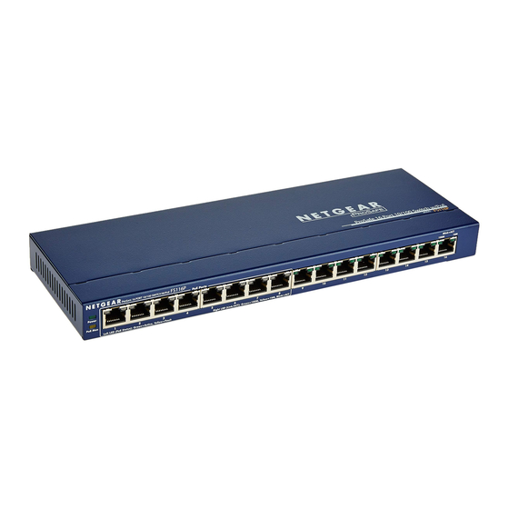
ProSafe 16 Port 10/100 Desktop Switch with 8 Port PoE FS116P
Installation guide,
Warranty/support information card
When you open the box, verify that you received everything.
The package includes:
・ ProSafe 16 Port 10/100 Desktop Switch with 8 Port PoE FS116P
・ AC power adapter and power cord
・ Wall-mounting screws
・ FS116P Installation Guide (this document)
・ Warranty and support information card
If you don't have everything listed above, see the support information card for contact information. If
you're missing the Technical Support information card itself, get contact information at
www.NETGEAR.com in the Customer Service area.
2
2
Prepare to Install the Switch
Decide where you want to place the switch. Find a flat horizontal surface - such as a table, desk or shelf. The
switch comes with wall-mounting screws. You're welcome to use the screws if you want to hang the switch
in an open space on a wall. Make sure the selected location is:
・ Not in direct sunlight or near a heater or heating vent.
・ Not cluttered or crowded. There should be at least 2 inches (5 cm) of clear space on all sides of the
switch.
・ Well ventilated (especially if it is in a closet).
Also, you'll need one Category 5 (Cat 5) Ethernet cable with RJ-45 connectors for each device you want to
connect to the switch. Each Ethernet cable must be less than 328 feet (100 meters).
LED Definitions
System LED:
Power
On (Green)
The FS116P is power on.
Off
Power is not being supplied to the unit.
PoE Status LED (Port 1 ~ Port 8):
Green
The PoE powered device (PD) is connected and
the port is supplying power successfully.
Yellow
Indicates one of the following failures resulted in stopping power
to that port:
• Short circuit on PoE power circuit
• PoE power demand exceeds power available
• PoE current exceeds PD's classification
• Out of proper voltage band (44 ~ 57 VDC)
Off
No PoE powered device (PD) connected.
PoE MAX
On (Yellow)
Indicates less than 7W of PoE power is available
Blinking (Yellow) Indicates the PoE MAX LED was active in the previous two minutes
Off
There is at least 7W of PoE power available for another device
PoE LED example 1:
4 PDs are connected to FS116P (Port 1 ~ Port 4) consuming 50W, leaving 5W of power available. The PoE MAX LED
will light up, as there is less than 7W of power available. The FS116P will not provide power to any newly connected PD.
The 5W of power is reserved for power surges by the original PD devices.
PoE LED example 2:
Port 1, Port 2, Port 3 and Port 4 all have PD's drawing 13W, for a total power draw of 52W. Since the remaining power
is less than 7W, the PoE MAX LED will light up. If all of the PD's surge to 14W, thereby exceeding the power budget
(55W), Port 4 will stop providing power since it has the lowest priority of the ports providing power. The power from
Port 4 will be allocated to provide power the other ports. (If the ports are plugged in at the same time, priority is based on
port number.) The PoE status LED for Port 4 will turn yellow, and the PoE MAX LED will turn off, since there is now
more than 7W available.
Ethernet Port Status LED (Port 1 ~ Port 8):
Link/ACT
Green
A 100M link has been successfully established on the port.
Blinking
The port is transmitting or receiving data.
Yellow
A 10M link has been successfully established on the port.
Blinking
The port is transmitting or receiving data
Off
No link.
Ethernet Port Status LED (Port 9 ~ Port 16):
100M
On
A 100M link has been successfully established on the port.
Blinking
The port is transmitting or receiving data.
Off
No link.
10M
On
A 10M link has been successfully established on the port.
Blinking
The port is transmitting or receiving data.
Off
No link.
Wall-mount
hardware
Power cord
Power adapter
3
3
Install the Switch and Connect the
Other Devices
ProSafe 16 Port 10/100 Desktop Switch with 8 Port PoE FS116P
1.
Place the switch on a flat surface or hook onto the screws.
2.
For each device, insert one end of an Ethernet cable into the port in the device and insert the other end
into one of the Ethernet ports on the switch. Note: If you have more than 8 devices to connect to this
switch, you must connect them to a switch and then connect that switch to this switch.
3.
Connect the power adapter's cord into the back of the switch and then plug the adapter into a power
source (such as a wall socket or power strip).The Power light should light up. The corresponding
10M/100M LED for each connected and powered device should light when link (connection), and
flash when activity occurs. Note: If any light doesn't operate as indicated, go to the Trouble shooting
section.
4.
Connect PDs to Port 1 ~ Port 8 of FS116P. These PoE ports will automatically activate when a
compatible device is connected. The FS116P will not provide power to PD devices that are not
compatible with the PoE Standard IEEE 802.3af. This feature allows users to freely and safely mix
legacy and standards-based PoE devices on their network without concern for damaging equipment.
(Please refer to LED Definitions section for more detail on PoE LED examples)
Front Panel:
Front panel of FS116P
DC Power Jack: Power is supplied through an external DC power adapter. Check the technical
specification section for information about the DC power input voltage.
Note: Be sure to connect 48V/1.45A power adapter DC plug to DC jack of FS116P before plugging the
power cord to AC power outlet.
Grounding Connection: A grounding strap location is provided to enable you to ground the case to
Earth.
Troubleshooting
The Power light is not lit
The switch has no power.
・ Make sure the power cord is properly connected to the switch.
・ Make sure the power adapter is properly connected to a functioning power outlet. If it's in a power
strip, make sure the power strip is turned on. If the socket is controlled by a light switch, make sure the
switch is in the on position.
・ Make sure you are using the NETGEAR power adapter supplied with your switch.
The Link/Activity is not lit for a connected device or stays on continuously
There's a hardware connection problem.
・ Make sure the cable connectors are securely plugged in at the switch and the device.
・ Make sure the connected device is turned on.
・ If the Ethernet cable is connected to a NIC or other Ethernet adapter make sure the card or adapter is
installed correctly and is working.
・ Make sure the cable is less than 328 feet (100 meters).
Technical Specifications
Standards Compatibility:
IEEE 802.3i 10BASE-TEthernet, IEEE 802.3u, 100BASE-TX Fast Ethernet,
IEEE 802.3x Flow Control, IEEE 802.3af Power over Ethernet; compatible with
Windows®, Mac®OS, NetWare®, Linux®
Data Rate:
100 Mbps with 4B/5B encoding and MLT-3 physical interface for 100BASE-TX
10 or 100 Mbps half-duplex Network Interface: RJ-45 connector for 10BASE-T or
100BASE-TX Ethernet interface
Port Description:
10/100Mbps Auto-Uplink RJ45 ports with PoE enabled (port 1 ~ port 8)
10/100Mbps Auto-Uplink RJ45 ports (port 9 ~ port 16)
DC Power:
69.6W max and 48V @ 1.45ADC input
PoE Power Budget:
55W max (all PoE ports, port 1 to port 8), 15.4W max per PoE port
Physical Dimensions:
W: 286mm (11.25") D: 100.6 mm (3.96") H: 25.9mm (1.01")
Weight:
0.84kg (1.85 lbs)
Operating Temperature:
0 to 40° C (32 to 104° F)
Operating Humidity:
10% to 90% relative humidity, non-condensing
Electromagnetic Compliance:
CE Class A; FCC Part 15, Class A; VCCI Class A; C-Tick
Safety Agency Approvals:
CE/LVD
Performance Specifications
Frame Filter Rate:
14,800 frames/sec max for 10M port / 148,800 frames/sec max for 100M port
Frame Forward Rate:
14,800 frames/sec max for 10M port / 148,800 frames/sec max for 100M port
100 Mbps to 100 Mbps: 20 µs max (using 64-byte packets)
Network Latency:
Address Database Size:
8192 MAC addresses
Addressing:
48-bit MAC address
Queue Buffer:
1.25 Mbit
DSL-
Modem
ProSafe VPN-Firewall FVS318
Real Panel:
Real Panel of FS116P
Advertisement
Table of Contents


Need help?
Do you have a question about the FS116P and is the answer not in the manual?
Questions and answers