Table of Contents
Advertisement
Quick Links
Advertisement
Table of Contents

Related Manuals for JINMA YL254Y HST


Summary of Contents for JINMA YL254Y HST
- Page 1 Operation Manual Jinma USA LLC...
-
Page 2: Preface
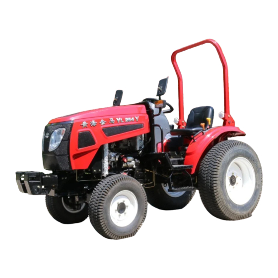
Preface Welcome to be a user of Huanghai Jinma YL254Y gardening wheel tractor. This model has reasonable structure, high-quality materials and perfect performance. It has characteristics of stong horsepower, low fuel consumption, light and flexible, easy operation, simple maintenance and is suitable for a variety of gardening or field operations. We have written this instruction manual to help the user better master the use, adjustment, repair and maintenance of this series of models and make full use of the effectiveness and superiority of this series of models. - Page 3 About this manual This instruction manual provides information on the use of the tractors, such as the uses specified by the manufacturer and the conditions predicted by the manufacturer during normal operation and routine repairs and maintenance. Please read and understand and keep this manual in good condition for future reference at all times.
- Page 4 and follow the information on this manual, assembly instructions or other conversion information partly specified by the manufacturer to execute. Repairing refers to the purpose of restoring the tractor to normal operation after a malfunction or performance degradation, must be performed by professional service staff who are familiar with the characteristics of the tractor to perform in compliance with the repair information in the dealer's factory operating instructions specified by the manufacturer.
- Page 5 related to this product. Any modification to the tractor is prohibited unless specifically authorized in writing by the company's After Sales Department. Warranty Your tractor is warranted according to the contract agreement between the dealers in your area. If the use, adjustment and maintenance of the tractor not according to the instructions provided by the manual, the warranty will not apply.
-
Page 6: Product Identification Mark Record Form
9# NenJiang Road, Yancheng Economic and Company address Technological Development Zone, Jiangsu,China Company contact number 0086-515-68823978/68829666 Huanghai Jinma YL254Y Gardening Wheeled TractorManual Jiangsu Yueda Intelligent Agricultural Equipment Company Edited Format 787×1092 1/16 Number Z01-10-001 First Version on June,2021 First Printing on June,2021... - Page 7 Common measurement units, symbols and names Number Type International unit Second -s Time Minute -min Hour -h Millimeter -mm Centimeter -cm Distance Meter -m Kilometer (km)-km New (ton)-N Power Thousand Newtons (tons)-kN Torque Newton·meter -N.m quality Kilogram (kg)-kg Pa -Pa Pressure KPa -kPa MPa -Mpa...
-
Page 8: Table Of Contents
Content Preface Notes for Owners Product Identification Mark Record Form Table of common units Chapter 1 Precautions for safe operation ......................1 Chapter 2 Overview ............................... 8 Chapter 3 Main technical specifications of tractor ..................... 9 3.1 Complete machine parameters ....................... 9 3.2 Transmission system .......................... - Page 9 6.1 Clutch adjustment ..........................29 6.2 Brake adjustment ..........................30 6.3 Adjustment of central transmission and differential ................ 31 6.4 Wheel track adjustment ........................34 6.5 Power output adjustment ........................34 6.6 Adjustment of the auxiliary gear lever .................... 35 6.7 Adjustment of the front drive joystick .....................
-
Page 10: Chapter 1 Precautions For Safe Operation
Chapter 1. Precautions for safe operation 1.1 The driver must be specially trained, get a driver’s license and be tested on time, and then use the tractor after reading the instructions carefully. 1.2 It is strictly forbidden to drive the tractor without a license and to operate without a license. - Page 11 Close to the Warning: Heat muffler source parts Warning: Engine Close pulley pulley Warning: Please read the instruction On the right side manual before operating dashboard machine Above the PTO Warning: PTO shaft protective cover Warning: When operating the lifter, At the center of stand the end of the...
- Page 12 Warning: Be sure to lock safety frame in an upright On the left side position, unless it safety must be allowed to frame operate under trees or bushes Both sides of the Warning: Heat radiator source parts clearly visible. On the right side Warning: Repair of the meter Warning:...
- Page 13 upper 1-12 Diesel fuel end of the fuel tank Above the start 1-13 Start control switch 1-14 Engine stop button Above the key Parking brake Near the hand 1-15 control brake assembly Two-wheel drive & Near the front 1-16 four-wheel drive drive handle Near 1-17...
- Page 14 Near the lifter 1-20 Lifter control handle Close 1-21 Gearbox refueling gearbox fuel port Near the hood 1-22 Hood lock switch lock 1-23 (Near) Headlight Control panel 1-24 (Far) Headlight Control panel Left and right turn 1-25 Control panel signals Emergency warning 1-26 Control panel...
- Page 15 people between the tractor and the agricultural implement or trailer. 1.10 Do not start or manipulate the tractor off the position of the driver's seat. Before starting the tractor, place the gear levers in the "neutral" position. Before leaving the driver's seat, the gear levers must be placed in the "neutral"...
- Page 16 1.20 The grass clippings, dust and other debris on the heat dissipation water tank should be eliminated in time to ensure its heat dissipation effect. When the water tank is overheated, it is forbidden to pour the engine and water tank with cold water to prevent the cylinder from breaking.
- Page 17 Position of front lifting jack Position of rear lifting jack 1.27 When getting on or getting off the tractor, you need to use the tractor's pedals (C) and hold the handrails (A) and (B) to prevent falling (as shown in the right picture). When the tractor is moving, never getting on or getting off the tractor;...
- Page 18 the transmission mechanism protective cover must always be in position. 1.34 Check the hydraulic hoses for oil leakage, kinks, cuts, cracks, wear, corrosion, steel wire leakage or any other damage at least once every six months. 1.35 Welding or heating near high-pressure liquid pipelines or other combustible materials is prohibited.
-
Page 19: Chapter 2 Overview
Chapter 2 Overview Huanghai JInma YL254Y is a new type of gardening tractor which is mainly suitable for a variety of home gardening operations developed according to the needs of a new generation of small gardening tractors. The characteristics of this model are: light, flexible, versatile and beautiful. - Page 20 Chapter 3 Key technical specifications of tractor 3.1 Parameters of whole unit Type YL254Y Engine model 403J-11 Type 4 4 four-wheel drive Inlet type Inhale naturally 3×77×81 Displacement 1.131 Rated power 18.4 Rated speed r/min 2800 Max torque/speed Nm/r/min 66.9/2100 Variable load average fuel consumption rate g/Kw h...
-
Page 21: Transmission System
Mini ground clearance Turning radius 3.50 Structure quality 1080 Mini use quality 1267 quality Front distribut Rear Quality kg Counter Front weight (standar Rear 0 8.2 Forward Theoritical speed High 0 20.0 of each gear Reverse 0 8.2 Km/h High 0 20.0 Note: The tires are optional, and the parameters will vary with the selected components. -
Page 22: Working Equipment
Rear wheel 80 120 Toe in mm Front wheel 3.5° camber Wheel alignment main pin 7.5° inclination Caster angle 0° Front axle swing angle 10° Steering angle 45° Type Hydraulic steering Model 109R-1-50-08-D-YT Steering Pressure 8±0.5 Flow L/min Service brake Double pedal disc brake Brake Parking brake... -
Page 23: Perfusion Capacity
3.5 Perfusion capacity Fuel 20.0 Engine sump capacity L Gearbox-rear axle lubrication 18.8 Cooling water Front drive axle capacity 3.6Electric components Electrical System Negative ground Battery C603-80Ah Maintenance-free Combination instrument 164Y.48.042 Headlamp C201-025/026 Rear tail light C207-004 Horn C502-015 Front position light C202-007 working light C203-012... -
Page 24: Chapter 4 The Use Of Tractor
Chapter 4 The use of tractor 4.1 Fuel and lubrication of tractor For tractor fuel and lubrication oil, see Table 4-1. Application Season and ambient temperature Specification Summer (ambient temperature 0,-10 light diesel GB/T 252-2000 above 10℃) Fuel tank Winter (ambient temperature -10 light diesel GB/T 252-2000 below 10℃) -
Page 25: Coolant Of Tractor
use of a filter. Do not fill up the fuel to allow it to evaporate, and then tighten the fuel tank cap after refueling. 2 Refuel before the fuel tank is empty. If the oil in the supply system runs out, the air must be drained before refueling. -
Page 26: Running-In Of Tractor
water tank. 2 When the coolant temperature in the water tank exceeds 100°C, the engine should be turned off immediately and necessary inspections and repairs should be made after the water tank has cooled down. 4.3 Running-in of tractors New tractors or overhauled tractors must be run-in before use. There will be different degrees of knife marks on the upper surface after the parts are processed. - Page 27 4.3.3 Tractor idling and load running-in The running-in of the tractor should be carried out at the rated speed of the engine. During the running-in process, if there’s an abnormal phenomenon or malfunction, the cause should be found out immediately and the running-in can be continued after troubleshooting.
-
Page 28: Instruments And Controls
4.4 Instruments and controls Familiar with the functions of various control devices, indicating instruments and understanding their positions on the tractor (see Figure 4-1), which are necessary for the correct use of the tractor. 1 Combination instrument—— indicating water temperature gauge, oil pressure gauge, tachometer, oil gauge, voltmeter, etc 2 Knob switch——main light switch, horn switch, steering switch, headlight switch, position light switch... - Page 29 17 Lifter joystick——Push the lifter handle forward to lower the agricultural implement; pull the handle back to raise the agricultural implement. Figure4-1 Control device and indicating instrument 4.5 Operating and driving Caution 1 The driver must be specially trained, get a driver's license and be tested on time, then use the tractor after reading the manual carefully.
- Page 30 6 When the head tilt phenomenon occurs in operation, the speed should be decreased immediately and the load should be removed to prevent the tractor from overturning longitudinally. 7 When the engine speeds up, the load is not allowed to be removed, the power supply should be turned off quickly and the fuel supply circuit should be disconnected.
- Page 31 Caution If the tractor is driving on flat ground, do not move your foot off the speed control pedal for fear of hurting yourself. 4.5.3 The start-up of the tractor Run the engine at a moderate speed for 5-10 minutes to warm up the engine till the water temperature rises above 70°C, the following steps can be used to start the engine 1 Lift up suspension agricultural implements.
- Page 32 High gear is 0 /h~20 Reverse speed range Low gear is 0 /h~8.2 High gear is 0 /h~20 6 The tractor has a wide speed range that can meet the operation requirements of supporting a variety of agricultural complements: Speed of working /h~6 Mainly used for mowing, rotary tillage and other operations;...
-
Page 33: Operation And Use Of Tractor Working Device
avoid sharp brake wear or engine shutdown. If the tractor is parked for a long time, turn off the engine according to the following steps 1 Decrease the engine speed to reduce the tractor driving speed. 2 Depress the clutch pedal quickly and push the auxiliary transmission to the low gear position. - Page 34 Caution 1 A safety shield should be added when using the power output shaft and it is strictly forbidden to stand on the shield. The PTO shaft sleeve should be installed when the PTO shaft is not used,; 2 When selecting farm tools, the rotation speed of the farm implements should match the rotation speed of the tractor's power output shaft;...
- Page 35 When using the position adjustment, the lifting position of the agricultural implement is realized by flipping the distributor control handle and adjusting the position of the limit block on the return push rod. When the application requirements are met, the block is fastened to the push rod with bolts.
- Page 36 Adjust the length of the pull rod to keep the plow frame horizontal in the longitudinal direction to achieve the same plough depth. When the front part plow is deep, the rear part plow or the plow heel leaves the bottom of the ditch, the upper pull rod should be extended; when the front part is shallow, the back part is deep or the plough heel presses the bottom of the ditch very tightly, the upper pull rod should be shortened.
- Page 37 raised off the ground to avoid damaging the lifting system and suspension system. 4 When heavy agricultural implements are connected, the lift handle should be moved up slowly to prevent the tractor from overturning. 5 The trailer should be connected to the traction plate. 6 Before the person leaves the tractor, the suspended implement must be lowered to the ground.
-
Page 38: Front Traction Mechanism
differential lock to avoid impact on the transmission box. 3 After the tractor passes through the skid zone, immediately release the differential lock pedal to make it return automatically. 4.6.4 Use of front drive axle Four-wheel drive tractors can be engaged with the front drive axle to achieve four-wheel drive when working under heavy loads or working on wet and soft soil. -
Page 39: The Location And Use Of The Battery
4.8.1 Installation 1 Install (A) front counterweight bracket; 2 Use lifting equipment to install (D) counterweight 3 Install the fixing bolt (C) and nut (B); 4.8.2 Dismantling 1 Dismantle the fixing bolt (C) and nut (B); 2 Use lifting equipment to remove (D) counterweight 3 Put it on level ground Caution: When the implement is suspended, the front wheels of the tractor may lift up. -
Page 40: Operation Of Electrical Equipment
Caution: The gas released by the battery can cause an explosion, keeping the battery away from sparks and flames. 4.10 Operation of electrical equipment Tractor electrical equipment is mainly used for the starting of the tractor to meet the requirements of sending out signals and night lighting. The electrical system adopts 12V negative ground single wire control. - Page 41 Warning (1) It is strictly forbidden to disassemble the battery when the engine is running. Do not let your eyes, hands or clothes contact with electrolytes. If you contact accidentally, please wash them thoroughly with clean water. (2) Maintenance of electrical equipment can only be performed after disconnecting the grounding cable and the battery.
- Page 42 B. Check the commutator and brushes. If the surface of the commutator is severely ablated, it can be polished with fine sandpaper. The brushes should be replaced when they are excessively worn or broken. Lubricate the moving parts such as bearings. 4.10.3 Starter (1) The contact points of the starter and all wires should be kept clean regularly during use.
- Page 43 should be shut down for inspection in time in the event of a failure. If it is damaged, the accessories of the same model should be replaced as required and other substitute accessories should not be used. Battery charging warning light (red): After the engine is started, the light turns from on to off indicating that the generator is working normally.
- Page 44 Oil level alarm indicator light (red): When the oil level is less than or equal to 1/8, the indicator light is on and the buzzer sounds intermittently; when the fuel sensor has an open circuit or short circuit fault, the indicator light is on. Parking brake indicator light (red): When the parking brake handle is in the braking position, this light is on which indicating that the tractor is in the braking state.
- Page 45 1--Relay 2 3--Fuse 4 5 6--Connector 7—Fuse clip 8--Flasher 4.10.7 Warm-up start switch The warm-up start switch is used to connect the whole vehicle circuit to start and warm up the engine. Insert the start key into the start switch, rotate the switch clockwise to I gear to connect the whole vehicle circuit.
- Page 46 circuit. 4.10.8 Two-way switch Hazard warning light switch "POS1": When the vehicle is in a critical situation, press the switch to the POS1. Then the left and right turn signals are flashing and the left and right turn indicators on the instrument also flash. "POS3": cut off the power supply.
-
Page 47: Chapter 5 Technical Maintenance Of Tractors
Chapter 5 Technical maintenance of tractors It is very important for the user to grasp the state of the tractor every time before driving in order to ensure that the tractor is always in good condition, which avoid sudden failures during the use of the tractor and cause components damage and personal injury. - Page 48 (5) Check whether the coolant in the radiator is full, wash and clean the weeds and clippings between the radiators so as not to affect the effect of the radiator. (6) Check whether there is dirt and water in the fuel sedimentation cup. Eliminate it if necessary and exhaust the air in the oil pipes.
- Page 49 5.4 Third-class technical maintenance Carry out the following maintenance after every 500 hours of work: (1) Finish the second-class technical maintenance project. (2) Check and adjust the valve clearance, injector pressure and spray atomization of the injector according to the requirements of the diesel engine operating manual. (3) Flush the fuel tank and fuel filter.
-
Page 50: Technical Maintenance For Long-Term Storage
well as the clearance and pre-load of bearing. (8) Clean the filter in the hydraulic lifting system and replace the oil in the system with fresh oil. (9) Clean the steering gear and replace the lubricating oil. (10) After the above maintenance is completed, a short-time test run is carried out to check for normal operation. - Page 51 Caution (1) This machine can only be maintained and repaired by personnel who are familiar with the tractor and have relevant knowledge of safety operation. (2) Should read this manual and the parts catalogue of diesel engine carefully before maintenance.
-
Page 52: Chapter 6 Main Adjustments Of The Tractor
Chapter 6 Main adjustments of the tractor 6.1 Clutch adjustment The clutch should be checked and adjusted frequently during use. The clearance between the release pawl and the end face of the release bearing is gradually reduced which will cause the head of release pawl contacts with release bearing. - Page 53 between the clutch control board and the start switch contact by 2~3mm after the clutch pedal is depressed and then tighten the nut (7) (See Figure 6-1). 6. 1.4 Lubrication of clutch system The front bearing of the clutch should be fully greased when assembling. The release bearing does not need to be refilled grease under normal conditions.
- Page 54 Brake adjusting Figure 6-2 Brake operating 1 Brake switch 2 Brake pedal 3 Brake interlock 4 Return spring 5 Pull rod 6 Hand brake 7 Hand brake cable 6.2.1 Adjusting free travel of brake pedal The free travel of the pedal is the displacement measured from the highest position of the pedal to the position where you are begin to feel resistance when pressing the pedal.
- Page 55 6.2.3 Adjusting brake switch and hand brake switch Adjust the working stroke of the brake pedal and the nut on the pull rod before you can adjust the brake switch (1) so that the contact between the pedal control board and the brake switch is compressed by 2~3mm and always in a constant engagement state.
- Page 56 拖 拉 机 前 进 方 向 Figure 6-3 Central drive and differential 1 Driving conical gear 2 Stop ring 3 Deep groove ball bearings 6305N 4 Deep groove ball bearings 6305 5 6 Deep groove ball bearings 6010 Adjusting shim 7 Differential side gear gasket 8 Planet gear 9 Planet gear shaft 10 Planet Gear Gasket 11 Passive conical gear 12 Deep groove ball bearings 6209...
- Page 57 spot-like but the length is not less than 60% of the teeth length and the height is not less than 50% of the teeth height. 2 Inspection of backlash and meshing prints Backlash inspection There are two inspection methods One is the dial gauge inspection. Place the contact of the dial indicator on the tooth surface of the big end of the large bevel gear, fix the small bevel gear and swing the large bevel gear in the direction of rotation.
- Page 58 Both the gear backlash and meshing prints will change during the normal use of the tractor. In this case, there is no need to readjust the gear backlash as long as the meshing print is normal and only the gear backlash increases. However, careful adjustments must be carried out after an overhaul of the tractor or replacing a new pair of central drive gears or conical bearings to ensure the gear backlash and meshing prints.
- Page 59 Adjustment of backlash and meshing prints Table 6-4 6.4 Adjustment of wheel track 6.4.1 Model of front tire Grass tire 26x7.5-12 or agricultural tires 6.0-12 the wheel track of the two types is the same. Model of rear tire Grass tire 11.2-20 or agricultural tires 11.2-20 the wheel track of the two types is the same.
- Page 60 stored for a long time. (7) Avoid prolonged exposure to the sun when parking. (8) Pay attention to safety and use special tools when dismantling tires. The inner and outer tires should be clean, dry and coated with talcum powder. 6.5 Adjustment of power output 6.5.1 Power output gear shift adjustment The position II shown in Figure 6-6 is the power output neutral gear.
-
Page 61: Adjustment Of The Front Drive Joystick
Adjustment of the auxiliary shift control lever Figure 6-7 1 Auxiliary shift control lever 2 Rocker 3 Auxiliary shift lever 4 Elastic cylindrical pin 6.7 Adjustment of the front drive joystick Pull the front drive control lever (1) to rotate the front drive control rocker arm, the front drive lever rocker arm in the gearbox connected to it will slide axially before the drive driven gear is moved. -
Page 62: Adjustment Of Hydraulic Steering
6.8 Adjustment of hydraulic steering 6.8.1 Installation of steering gear 1. Install the steering gear on the steering gear bracket and check whether the spring washer is in good condition. Mount the spring washer and fasten screw, tighten the fasten screw and place the steering gear in the neutral position. -
Page 63: Structure And Adjustment Of The Lifter
Follow the steps below to adjust and inspect the lifter. Please contact your local Huanghai Jinma supplier if necessary. 1 Connect the lock nuts on both sides of the connecting plate before loosen the neutral position feedback of the position feedback mechanism. -
Page 64: Intake And Exhaust System
3 Tighten the lock nut. Caution 1 Before checking the hydraulic system, turn off the engine and push the hydraulic handle to reduce the pressure in the system. 2 High-pressure oil will penetrate into the skin and cause injury. Be very careful when handling high-pressure oil and pay special attention not to spray the high-pressure oil to the eyes and other body parts. - Page 65 element needs to be maintained for a period of time. (If it is in a dusty environment, it needs to be maintained as soon as possible). Take out the filter element, use a soft brush to remove dust (Figure 6-15) and gently tap the surface. Seal both ends of the filter element and blow compressed air from the inside to the outside to remove the dust.
- Page 66 It will not protect people when the safety frame is folded. Please use the safety frame during operation, otherwise the tractor may roll over and cause personal injury. 6.11.2 Maintenance and inspection of safety frame This safety frame has been certified by industry and government standards. Any damages or changes to the hardware or seat belts installed in the safety frame will invalidate the certification and will reduce or eliminate the protection of operators.
- Page 67 Figure 6-18 Drawbar Certain heavy equipment, such as loaded single-axle trailers can put excessive pressure on the tow bar which would be greatly increased through rough roads and pressure of high-speed. The static vertical load on the hook should not exceed that shown on the chart. Caution Pulling from the wrong position on the tractor can lead to roll over.
-
Page 68: Diesel
Chapter 7 Main faults and troubleshooting methods Once the tractor breaks down in use, it should be stopped for inspection immediately and the cause should be found and eliminated according to the relevant content in the following table. Caution The user should contact the maintenance station set up by the factory or ask an experienced person for help when the work requires a high level of skill such as dismantling before overhauling or replacing new parts.. - Page 69 7.1.2 Insufficient power Cause of failure Troubleshooting methods 1. The air filter or diesel filter is clogged Clean the filter element with diesel or 2. The fuel supply advance angle is wrong kerosene 3. Diesel contains water Readjust to the specified value 4.
- Page 70 2 Piston and cylinder are locked, repair or replace cylinder, piston and other parts Cause of failure Troubleshooting methods 1. The diesel engine lacks water so that it Pay attention to refill cooling water overheats and locks the cylinder Eliminate scale 2.
-
Page 71: Transmission System
1. Diesel engine works with overloads Reduce the load. If it does not meet the 2. Exhaust gas with a lot of smoke which is matching requirements, adjust and reinstall caused by the reverse installation of the second the gas ring. Pay attention that the side gas ring or the severe wear of the oil ring marked with "Up"... - Page 72 1. There is oil stained on the surface of the Clean with diesel oil and troubleshoot oil friction plate leakage 2. The compression spring force is reduced or Replace the spring broken Readjust as required 3. The free travel is small or disappears and the Replace friction plate release levers are not in the same plane 4.
-
Page 73: Brake
1. The bearing clearance or conical gear backlash Readjust to the specified value is too small Fill lubricating oil to the specified oil level 2. Insufficient oil Fill the specified lubricating oil after cleaning 3. Poor oil quality with diesel oil 7.3 Brake 7.3.1 Brake failure Cause of failure... -
Page 74: Steering And Walking System
7.4 Steering gear and walking system 7.4.1 Difficulty steering Cause of failure Troubleshooting methods 1. The clearance is too large or severely worn Adjust the clearance or replace the wearing between the finger pin and the worm, or the parts screw nut assembly and the rocker gear fan, or Inflate as required the spherical worm and the roller... -
Page 75: Hydraulic Suspension System
7.4.4 Tire wear at early time Cause of failure Troubleshooting methods 1. Improper adjustment of the front toe-in Readjust to the specified value 2. Low tire air pressure Inflate as required 3. Driving wheels are assembled wrongly Re-assemble 7.5 Hydraulic suspension system 7.5.1 Farming implements cannot be lowered or raised Cause of failure Troubleshooting methods... -
Page 76: Electrical System
7.6 Electrical system 7.6.1 Starter Cause of failure Troubleshooting methods 1. The starter does not rotate Welding or screwing the contact point ①Broken or poor connection of the connecting Recharge or replace the battery wire Clean the commutator surface or replace the ②Insufficient battery charge brush ③Poor... - Page 77 7.6.2Battery Cause of failure Troubleshooting methods 1. The battery often has insufficient power Repair generator or regulator ①The generator or regulator is faulty and there Check whether the electric clamping chuck is no charging current and connecting wiring bolt are loose and ②...
- Page 78 Check and repair 1. The battery charging alarm light does not light up after Check and repair turning on the ignition start switch Replace the bulb with the same specification ①Fuse blown Repair, replace ②The excitation circuit is open Replace the voltage regulator of the same ③The filament of the charging alarm light is broken model ④The excitation coil is open...
- Page 79 7.6.4 Dashboard Cause of failure Troubleshooting methods 1. Abnormal indication of water temperature meter Overhaul ①The circuit from the dashboard to the water replace temperature sensor is open; the connector is in poor Overhaul and replace contact Overhaul ②Internal open circuit of water temperature sensor replace ③Internal failure of water temperature meter Overhaul and replace...
- Page 80 7.6.5Light Cause of failure Troubleshooting methods 1. The headlights have no high and low beam Replace ①Fuse blown Overhaul ②The circuit is broken Replace a good quality bulb ③The bulb is damaged Repair and replace ④The light switch is broken and the contacts are burnt Replace 2.
-
Page 81: Chapter 8 Delivery, Acceptance And Transportation
Chapter 8 Delivery, acceptance check and transportation 8.1 Delivery and acceptance check When a user purchases a tractor, he/she should check the purchased machine and focus on the following aspects: Attachment 8.1.1 It contains: "Tractor Instruction Manual", "Qualification Certificate", "Delivery List", "Engine Technical Documents", "Parts Catalogue", please check whether it is consistent with the whole machine number. - Page 82 First release the hand brake, put into forward gear and drive at the lowest speed when unloading. Caution The parking brake should be put on and the front and rear wheels should be firmly wedged to prevent the tractor and the operator from tilting or falling due to the sudden start of the tractor during loading and unloading.
-
Page 83: Chapter 9 Dismantling And Disposal
Chapter 9 Dismantling and disposal In order to protect the social environment and your personal safety, please send the machine to a recycling company with professional dismantling capabilities when the entire service life of the machine expires. Please disassemble the tractor from top to bottom, first outside and then inside. You must use professional slings when disassembling large or heavy objects. -
Page 84: Chapter 10 Warranty Matters
Chapter 10 Warranty matters 10.1 Basis of product warranty YL254Y garden wheeled tractors are guaranteed in accordance with the following documents and regulations. "Provisions on Responsibilities for Repair, Replacement and Return of Agricultural Machinery Products" Order No. 126 of the General Administration of Quality Supervision, Inspection and Quarantine of the People's Republic of China "Product Quality Law of the People's Republic of China";... - Page 85 months, 24 months for main components, 9 months for machines below 18.4 kilowatts and 18 months for main components. From the date of shipment (the warranty period for goods sold on credit in installments starts from the date of delivery). 2.Main parts: Engine body, cylinder head, flywheel, frame, gear box, semiaxle housing, steering gear housing, differential housing, main reducer housing, brake hub, drawplate, lifter housing.
- Page 86 The driver and the operator have not obtained a driving operation license in accordance with the law. Caused by force majeure. 10.3.4 Other If there is a conflict between this warranty rule and the "Regulations on Responsibilities for Repair, Replacement and Return of Agricultural Machinery Products", the "Regulations on Responsibilities for Repair, Replacement and Return of Agricultural Machinery Products"...
-
Page 87: Chapter 11 Appendix
Chapter 11 Appendix 11.1 Electrical system circuit diagram... -
Page 88: Distribution Map Of Tractor Transmission System And Rolling Bearing
11.2 Distribution of tractor transmission system and rolling bearing Figure 11-2 Diagram of tractor transmission system 11.3 Motion diagram of the tractor suspension system Motion diagram of the tractor suspension system Figure 11-3... - Page 89 11.4 Accessories list Code Name Wrench 8×10 Z04-024 Wrench 13×16 Double-headed solid wrench Wrench 18×21 GB/T4393 Wrench 22×24 Z03-016 C type protection cover of canopy Rain cover tractor Z03-0211 (230x137x120) Manual of diesel attachments etc. 1set YL254Y garden wheeled tractors parts Z02-YL-001 list Z01-YL-001...
-
Page 90: Implementation Of Standards, Orders And Laws
D07-3452.1-42.5X2.65 O seal ring 42.5×2.65 D07-3452.1-13.2X1.8 O seal ring13.2×1.8 11.6 Implementation of standards, orders and laws 1.GB/T 18447.1 Agricultural tractor safety requirements 2.GB/T 3871 Agricultural tractor test procedure 3.Q/320901 YNT 112.1-2021 YL254Y Garden wheel tractor technical conditions 4.GB 6376 Tractor noise limit standard 5.GB/T 19040 Agricultural tractor steering requirements 6.GB/T 9480-2001...
Need help?
Do you have a question about the YL254Y HST and is the answer not in the manual?
Questions and answers