Table of Contents
Advertisement
Quick Links
Advertisement
Table of Contents

Related Manuals for EXE XDDL Series

Summary of Contents for EXE XDDL Series
- Page 1 USE AND MAINTENANCE MANUAL XDDLxx Motor Controller Model: XDDL4 XDDL8 XDDL16 XDDL24 _ _ _ _ _ _ 20 _ _ Serial Number: Years of Construction : Official Language: ITALIAN Manual Language: ENGLISH TRANSLATION OF THE ORIGINAL INSTRUCTIONS Rev. 03 del 17/09/2018 Pag.
- Page 2 MANUFACTURER DISTRIBUTOR SRS LIGHT DESIGN s.r.o. LITEC ITALIA S.R.L. Rybnicna 36/D, SK- Via Martin Luther King 70, 83106 Bratislava, Slovak Republic I-31032 Casale sul Sile (TV), Italy Tel: +421244681417 Tel: +390422997300 www.srslight.com www.exetechnology.com sales@srslight.com, www.litectruss.com Keep this manual for future consultation. Provide this manual to all Motor Controller operators and maintenance technicians.
-
Page 3: Table Of Contents
1.3. REPAIR - REPLACEMENT - WARRANTY POLICY ..................6 MACHINE PRESENTATION ..........................8 2.1. INTENDED USE .............................. 8 2.2. IDENTIFICATION OF EXE-DRIVE MOTOR CONTROLLER ................. 9 2.3. GENERAL DESCRIPTION ..........................9 2.4. PRINCIPLE OF OPERATION ........................12 2.5. TECHNICAL DATA ............................14 2.5.1... - Page 4 EXE-Rise chain hoist link ATTACHED DOCUMENTATION This manual is an integral part of the EXE-Drive Motor Controller and contains the EXE-Drive Motor Controller Declaration of Conformity. The Declaration of Conformity is an integral part of the manual, therefore it is also an integral part of the EXE-Drive Motor Controller The Declaration of Conformity contains a list of directives and standards.
-
Page 5: General Information
1. GENERAL INFORMATION Thank you for choosing a XDDL Motor Controller from the EXE-Drive line produced by SRS and distributed by LITEC ITALIA. Do not use the Motor Controller EXE-Drive until all operators have read this manual thoroughly. Failure to follow these instructions could endanger the safety of individuals and/or lead to injuries or even death. -
Page 6: Safety Signs
1.3. REPAIR - REPLACEMENT - WARRANTY POLICY Before shipping, the performance of the EXE-Drive Motor Controller is checked by SRS or by authorized service centres. The manufacturer guarantees that upon delivery to the customer, the goods is free of manufacturing and material defects. - Page 7 WARRANTY PERIOD The EXE-Drive Motor Controller is provided with a limited warranty of one year from the date of purchase. The warranty covers the mechanical parts, excluding the electrical and others parts subject to wear. The warranty period starts on the day of delivery, substantiated by a purchase receipt such as an invoice or delivery note, or copies of them.
-
Page 8: Machine Presentation
2. MACHINE PRESENTATION The EXE-Drive Motor Controller is the result of years of experience in the structure moving sector for the entertainment and events industry. The high level of technology applied has led to the creation of a product that enhances the primary features of a Motor Controller combined with ease of use. -
Page 9: Identification Of Exe-Drive Motor Controller
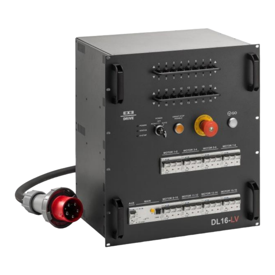
9. Made by: Company name and address of the manufacturer. 2.3. GENERAL DESCRIPTION The EXE-Drive Motor Controller was designed to meet safety standards. In fact, the device is equipped with: A general differential magnetothermic switch for protecting the entire machine. Adjustable magnetothermic protection for each motor output. - Page 10 DL8-LVC REAR VIEW FRONT VIEW Figure 7: “DL8-LVC Front and Rear View” DL16-LVC FRONT VIEW REAR VIEW Figure 8: “DL16-LVC Front and Rear View” Rev. 03 del 17/09/2018 Pag. 10 / 40...
- Page 11 FRONT VIEW Figure 9: “DL24-LVC Front and Rear View” The EXE-Drive Motor Controller was designed to manage up to 4/8/16/24 chain hoists that are electrically compatible, either separately or simultaneously, which are controlled through switches located on the front panel or using a wireless pushbutton panel. The GO/STOP buttons can be connected with a link connector.
-
Page 12: Principle Of Operation
2.4. PRINCIPLE OF OPERATION The Motor Controller was designed and built to simultaneously or individually manage from 1 to a maximum of 4/8/16/24 electric chain hoists that are electrically compatible. It can be operated in two modes: DIRECT: the Motor Controller will only operate with the commands located on the front of it. ... - Page 13 RED FLASHING: The emergency STOP button is active on the base unit GREEN: The unit is functioning normally / E-stop and RESET are not necessary. EMERGENCY STOP: is a red button. After the STOP button has been pressed, the system is locked in an inactive position and to restart it, the button must be turned clockwise.
-
Page 14: Technical Data
REMOTE/LINK CONNECTOR - Neutrik NC5-MAH/FAH: These are for connecting the electric chain hoists or an RCx remote digital connection. They can be controlled using a GO and STOP emergency button with an RH remote digital unit. Poles Function NOTE CMN data Common data Data- Less Data... -
Page 15: Exe-Rise Chain Hoist Link
DC/LVC LT XDDL24 DC/LVC Table 3: “EXE-Rise chain hoist link” The values in the table refer to the standard EXE-Drive Motor Controllers. On request it is possible to request a personalization. 2.6. AIRBORNE NOISE EMISSION The airborne noise emitted by the machine has sound power lower than 70dBA. -
Page 16: Safety Warnings
3. SAFETY WARNINGS The EXE-Drive Motor Controller should be used for the intended use by the manufacturer, as described in Chapter 2. Any modification that is unauthorized by the manufacturer or its distributor, which alters the functionality or is prohibited in the following manual, will be fully responsible for whoever performs them. -
Page 17: Special Safety Warnings
3.2. SPECIAL SAFETY WARNINGS Although the EXE-Drive Motor Controller is compliant with all European safety standards, using it isn’t without potential hazards. Check the operation procedures and warnings before using the Motor Controller. In this way, you will avoid jeopardizing your safety and that of others. Don’t improvise when faced with a question or unexpected occurrence. -
Page 18: Movement And Installation
UNPACKING AND MOVING THE MOTOR CONTROLLER ON THE FLOOR Remove the EXE-Drive Motor Controller from its package and make sure the information shown on the data plate are the same as on the transport document and that no damage was caused by inadequate transport. -
Page 19: Use
EXE-Drive Motor Controller are protected from any external dangers. The IP20 protection rating indicates that when the EXE-Drive Motor Controller is used in open areas it is not protected, therefore adequate protection of the entire body of the Motor Controller is necessary. - Page 20 CONNECTING THE EXE-DRIVE MOTOR CONTROLLER Using a link connector located on the front panel 9 EXE-Drive Motor Controllers or 8 EXE-Drive Motor Controllers + 1 XRH-C pushbutton panel can be connected. For connection, a 5-pole DMX data cable with 1, 2, 3 assembled pins is indispensable.
-
Page 21: Control Unit Startup
and operate them remotely. The standard communication line is RS485. The specified maximum cable length is 1 m. SOFTWARE UPDATE The controller software can be updated through a USB drive or link cable. Contact the manufacturer for information related to the software. The link cable can also be used to display a synoptic map on a MAC or 5.3. -
Page 22: Using The Equipment In Individual Mode With The Xdrh Pushbutton Panel
4) The main differential switch for the equipment is in the OFF position. 5) Check the back of the equipment to make sure there are no wires hooked up to the XLR 5 pole connectors (link connection) and the XLR 4 pole connectors (Limit Stop). 6) Make sure the SOCAPEX-CEE adapters are hooked to the SOCAPEX 19-pin panel outlets located on the back of the controller and that the electric chain hoists that are intended to be used are hooked to the adapters. - Page 23 1) Make sure the “EMERGENCY STOP” mushroom button is in the rest position and not pressed on both the EXE-Drive Motor Controller and the XDRH_C remote pushbutton panel. 2) The circuit breakers (motor 1-4 – motor 1-8 – motor 1-16 – motor 1-24) are in the ON position.
-
Page 24: Use In "Link" Between Controller Mode
1) Make sure the “EMERGENCY STOP” mushroom button is in the rest position and not pressed on both all EXE-Drive Motor Controllers and that are intended to be used. 2) The 4 circuit breakers (motor 1-4 – motor 1-8 – motor 1-16 – motor 1-24) are in the ON position on all Motor Controllers that are intended to be used. - Page 25 b) Repeat the procedure described in the previous point for the “n” controllers to be linked (up to a maximum of 8 units). The last Motor Controller connected to the series will have the XLR5 female panel outlet free (link out). 6) Make sure that for all controllers to be used the SOCAPEX-CEE adapters are hooked to the SOCAPEX 19-pin panel outlets located on the back of the controller and that the electric chain hoists that are intended to be used are hooked to the adapters.
-
Page 26: Use In "Link" Between Controller Mode With Xdrh Pushbutton Panel
d) The white and green hoist up/down selection LEDs will flash alternately on each device as they are enabled. e) With the GO buttons disabled, if pressed, the related indicator lights remain off. Enable the system again on the XDDL_ MASTER device, engage and release the “EMERGENCY iii. - Page 27 6) Make sure that for all controllers to be used the SOCAPEX-CEE adapters are hooked to the SOCAPEX 19-pin panel outlets located on the back of the controller and that the electric chain hoists that are intended to be used are hooked to the adapters. 7) Plug each device into the 32A 400V 3P+N+T 6h 50hz mains.
-
Page 28: Use In Pickle Mode With The Xclh1 Pushbutton Panel
The white and green hoist up/down selection LEDs will flash alternately on each device as they are enabled. With the GO buttons disabled, if pressed, the related indicator lights remain off. b) Enable the XDRHG pushbutton panel as the “MASTER” device, engaging and releasing the “EMERGENCY STOP”... - Page 29 ii. “Status” LED off is on steady red to indicate the device is locked. iii. “E-Stop” LED orange c) Rearming the switches in the rest position to the ON position, c) If attempting to enable the device by engaging and releasing the “EMERGENCY STOP”...
- Page 30 TROUBLESHOOTING TROUBLESHOOTING (LINK MODE WITHOUT PUSHBUTTON PANEL) (LINK MODE WITH PUSHBUTTON PANEL) CASE 1 :If upon startup of the linked “n” Motor Controllers at least one of the circuit breakers on the system is in the OFF position: On all Motor Controllers: a) On the STOP &...
-
Page 31: Emergency Interventions
5.5. EMERGENCY INTERVENTIONS EMERGENCY AND SOLUTION EMERGENCY AND SOLUTION (SINGLE MODE WITHOUT PUSHBUTTON (SINGLE MODE WITH PUSHBUTTON PANEL) PANEL) If during the manoeuvre, with the GO button pressed, one of the 4 circuit breakers is tripped (switching to the OFF position), the device will shut down immediately and the failure situation will be indicated as follows: “Status”... - Page 32 EMERGENCY AND SOLUTION EMERGENCY AND SOLUTION (LINK MODE WITHOUT PUSHBUTTON PANEL) (LINK MODE WITH PUSHBUTTON PANEL) If during the manoeuvre, thus with the GO button on the MASTER pressed, any of the circuit breakers is tripped (switching to the OFF position), the device will shut down immediately and the failure situation will be indicated as follows: “Status”...
-
Page 33: Inspections
INITIAL INSPECTION AND AT EVERY USE The purpose of the following inspection is to make sure the EXE-Drive Motor Controller is properly assembled, installed, undamaged, and safe to use. SRS recommends performing the list of inspections provided below During handling and storage of the Motor Controller, safe movement techniques must be used. -
Page 34: Extraordinary Inspection
Any shortcomings must be corrected before the Motor Controller is put back into service. Be aware of the fact that external conditions may show the need for more detailed inspections. EXTRAORDINARY INSPECTION In the case of extraordinary events that could compromise the safety of the Motor Controller, an extraordinary inspection must be performed. -
Page 35: Declaration Of Conformity
8. DECLARATION OF CONFORMITY Figure 16: “Declaration of Conformity example” The original declaration of conformity, compiled in all parts, dated and signed, is attached to this manual. Rev. 03 del 17/09/2018 Pag. 35 / 40... -
Page 36: Maintenance And Repairs Registry
9. MAINTENANCE AND REPAIRS REGISTRY DATE ACTIVITIES RESULT NOTES SIGNATURE Rev. 03 del 17/09/2018 Pag. 36 / 40... - Page 37 DATE ACTIVITIES RESULT NOTES SIGNATURE Rev. 03 del 17/09/2018 Pag. 37 / 40...
- Page 38 Rev. 03 del 17/09/2018 Pag. 38 / 40...
- Page 39 EXE-DRIVE MOTOR CONTROLLER DISTRIBUTED EXCLUSIVELY BY LITEC Italia srl Via Martin Luther King, 70 31032 Casale sul Sile (TV) Italy Tel. +39 0422 997.300 Fax +39 0422 997.399 www.exetechnology.com www.litectruss.com info@litectruss.com Copyright © LITEC Italia Srl. All rights reserved. Rev. 03 del 17/09/2018...
- Page 40 Rev. 03 del 17/09/2018 Pag. 40 / 40...
Need help?
Do you have a question about the XDDL Series and is the answer not in the manual?
Questions and answers