
Related Manuals for BOCI BLT 662H


Summary of Contents for BOCI BLT 662H
- Page 1 BLT 662H Product Manual Laser Cutting Head BLT 662H-QBH/QD/Q+/ADD Brilliant Optical Cutting Instrument...
- Page 2 BOCI is constantly updating/upgrading products, so our company reserves the right to modify the product models and descriptions in this manual without prior declaration.
-
Page 3: Table Of Contents
2. Replace the upper protective lens ......................19 3. Replace Lower protective lens ....................... 20 Appendix B - Mechanical Dimensions ..............21 1. Cutting head installation size ........................21 2. BLT 662H Interface type .......................... 22 3. Mechanical dimensions ........................... 23... -
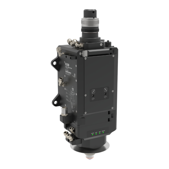
Page 4: Product Description
BLT662H Product Manual Product Description 1.1 Product View Product View (Structure and Interface Description) 1. Optical fiber interface; 9. Nozzle cooling air interface; 2. 1 Upper protective lens; 10. Cutting gas interface; 3. 2 Upper protective lens; 11. Cooling water outlet; 4. -
Page 5: Technical Parameters
BLT662H Product Manual 1.2 Technical Parameters Cutting head BLT662H Laser wavelength: 1030-1090nm ≤ Laser power: 20KW Fiber interface: QBH,QD,Q+,ADD Spot magnification: M=2.0 Focus adjustment range: ±50mm (optical ratio 1:2 100:200) Max.0.13 at Fc100 Centering adjustment range: ±1.5mm Focus acceleration: 7.5m/s² Cutting gas interface: ø10, maximum 25bar (2.5Mpa) Nozzle cooling gas connection:... -
Page 6: Meaning Of Led Indicator
BLT662H Product Manual 1.3 Meaning of LED indicator icon state meaning green Power is normal. Under-voltage alarm: insufficient electrical power. No power supply: There is no power supply, the connection cable is broken, and the bright interface is loose. icon state meaning green... -
Page 7: Electrical Interface
BLT662H Product Manual 2. Electrical Interface PWE and aviation plug interface waterproof precautions: PWE interface and air plug interface are equipped with dust plugs from the factory. If the dust plug does not fall off, the protection level of IP64 can be achieved; at the same time, when the PWE cable and the air plug cable are well connected, IP64 can also be achieved;... -
Page 8: Bus System
BLT662H Product Manual 2.1 Bus System BCS210E Power Supply BLT662H Cutting head installation 220V AC wiring diagram Hypcut Slave HyPanel Station master Station Notice: The above wiring operations should only be performed by trained and professional personnel. When the cutting head is connected to the BCS210E, the BCS210E ... -
Page 9: Non-Bus Systems
BLT662H Product Manual 2.2 Non-bus Systems BCL4500A POWER BLT662H Cutting head installation 24V DC wiring diagram Cypcut Slave master Station Notice: The above wiring operations should only be performed by trained and professional personnel. When the cutting head is connected to the BCL4500A, the BCL4500A must be powered off. ... -
Page 10: Cutting Head Installation
BLT662H Product Manual 3. Cutting Head Installation During the installation of the cutting head, dust or dirt may accidentally enter the cutting head, contaminate the optical lens, and affect its normal functions. To prevent dust or dirt from entering the cutting head, please refer to the following methods for the installation of the cutting head:. -
Page 11: Specific Operation Process
BLT662H Product Manual 3.2 Specific Operation Process 3.2.1 Install Fiber 1. Preparation of clean bench Prepare the clean bench, start it up and ensure its functionality: Clean table type: vertical purification; cleanliness class: ISO 5, 100; average wind speed ≥ 0.4m/s Check that the equipment is clean and qualified (checks the cleanliness of the dust particle counter ), and confirm that the FFU purification unit is within the validity... - Page 12 BLT662H Product Manual 3. Clean and wipe the fiber interface of the cutting head Wipe the fiber interface of the cutting head with a clean cloth and anhydrous ethanol. 4. Check the laser fiber end face Remove the protective cap of the laser fiber, and irradiate the end face of the fiber with a strong flashlight to observe whether there is any pollution;...
- Page 13 BLT662H Product Manual 5. Tear off the protective film/remove the protective cap Remove the special protective cap/protective plug for the optical fiber interface on the cutting head. 6. Insert the laser fiber interface into the cutting head Align the fiber optic plug with the red dot, insert it into the unlocked fiber optic port, and ensure that it is inserted as far as it will go.
- Page 14 BLT662H Product Manual 6.2 QD Lock 6.3 Q+ Lock 6.3 Q+光纤接口 6.4 ADD Tighten Screws...
- Page 15 BLT662H Product Manual 7. Wrap and Seal After inserting the optical fiber, wrap and seal the interface between the optical fiber and the cutting head with tape.
-
Page 16: Mount The Cutting Head On The Backplane
BLT662H Product Manual 3.2.2 Mount the cutting head on the backplane The cutting head can be installed on the Z-axis backplane of the machine tool through four screws A, B, C, and D. When fixing the cutting head on the machine, it must be ensured that the cutting head is locked and there is no obvious movement. - Page 17 BLT662H Product Manual After the water pipe is connected, perform a water connection test to check whether the water pipe connection is leaky. Notice: Deionized/distilled water (conductivity < 10 μS/cm) specified by the laser manufacturer is recommended. Recommended cooling water setting value: cooling water pressure ≤5bar (0.5Mpa), water ...
-
Page 18: Gas Interface Connection
BLT662H Product Manual 3.2.4 Gas Interface Connection Connect the cutting gas pipe to the cooling gas pipe of the nozzle and tighten it with a wrench. Note: When using φ 12 air pipe, the air pipe interface of φ 12 in the fitting box needs replaced. -
Page 19: Installing The Ceramic Body And Nozzle
BLT662H Product Manual 3.2.5 Installing the ceramic body and nozzle Install the ceramic body and secure with the locking ring, then install the nozzle. Ceramic Part Locking Ring Nozzle Tightening the nozzle on the ceramic body by hand, Tighten the ceramic locking ring using a wrench. 3.2.6 Function Test Connect the laser cutting software to the cutting head to check whether the function of the cutting head is normal: A. -
Page 20: Beam Centering
BLT662H Product Manual 3.2.7 Beam Centering The adjusted laser beam must be in the center of the nozzle. adjustment screw Relative position of laser beam Tape pass Fail Manual alignment operation: Make sure the laser beam is turned off. Place scotch tape under the nozzle. Click to trigger a low-power laser pulse and assess the position of the laser beam relative to the nozzle through the penetration of the tape. -
Page 21: Appendix A - Maintenance
BLT662H Product Manual Appendix A - Maintenance 1. Schematic diagram of product structure Fiber Interface Upper Protective Lens Upper Protective Lens Door Drawer Upper Protective Lens D25.4x4mm Upper Protective Lens Drawer Upper Protective Lens D25.4x4mm Collimation Drawer Unit Collimating Length F100mm Focusing Lens Unit Focusing Length... -
Page 22: Replace The Upper Protective Lens
BLT662H Product Manual 2. Replace the upper protective lens Upper protective lens protective door Upper protective lens drawer Open the protective door of the 1 upper protective lens; Pull out the upper protective mirror drawer; Close the protective mirror drawer door to prevent dust from entering; Remove the pressure ring on the protective lens;... -
Page 23: Replace Lower Protective Lens
BLT662H Product Manual 3. Replace Lower protective lens Lower protective lens Door Lower protective lens Drawer Press the buckle to open the protective door of the lower protective mirror drawer; Pull out the lower protective mirror drawer; Close the protective door of the lower protective mirror drawer to prevent dust from entering;... -
Page 24: Appendix B - Mechanical Dimensions
BLT662H Product Manual Appendix B - Mechanical Dimensions 1. Cutting head installation size... -
Page 25: Blt 662H Interface Type
BLT662H Product Manual 2. BLT 662H Interface type 1. HC interface 2. PWE interface... -
Page 26: Mechanical Dimensions
BLT662H Product Manual 3. Mechanical dimensions... - Page 27 BLT662H Product Manual...
Need help?
Do you have a question about the BLT 662H and is the answer not in the manual?
Questions and answers