Advertisement
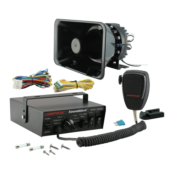
SoundAlert 100W Electric Airhorn Amplifier
Manual ID: PIM-00000201
IMPORTANT: READ CAREFULLY BEFORE ASSEMBLY AND USE.
•
Installer of this product must have a good understanding of automotive electronics,
systems, and procedures.
•
In the case that holes must be drilled in order to properly mount the product, the
installer must examine both sides of the mounting surface before drilling begins. It is
the installer's responsibility to be sure that no vehicle components or vital parts could
be damaged by the drilling process. De-burr any holes in order to remove metal shards
and remnants. Use grommets in all wire passage holes.
•
Do not attempt to activate or operate this product under hazardous driving situations.
•
Never operate the siren indoors or in an enclosed area.
DANGER!
Air horns are designed to produce extremely loud emergency warning tones!
Exposure to the tones produced without proper and adequate hearing protec-
tions, could lead to ear damage and/or hearing loss! The Occupational Safety &
Health Administration (www.osha.gov) provides information necessary to
determine safe exposure times in Occupational Noise Exposure Section 1910.95.
The operators of the siren and any one in the immediate vicinity of the siren
should be required to wear an approved hearing protection device until one has
determined the safe exposure times for your specific application. FAILURE TO
FOLLOW THIS RECOMMENDATION COULD CAUSE HEARING LOSS!
Mounting:
The air horn amplifier is designed to be mounted inside the engine bay around
the battery's vicinity. The air horn amplifier is waterproof and can be
mounted to an area exposed to the elements if necessary. If mounting the
amplifier to an area exposed to the elements, be sure that all wiring
connection and in-line fuse holder are made waterproof by using dielectric
grease, liquid electrical tape, or via other means.
WARNING! Make sure NOT to mount the air horn amplifier in the deployment
of any air bag. Refer to the air bag warning on the first page of this manual.
CAUTION! Permanent mounting of this product will require drilling. It is
absolutely necessary to make sure that no other vehicle components could be
damaged by this process. Check both sides of the mounting surface before
starting. If damage is likely, select a different mounting location.
Mounting of Air Horn Amplifier:
1. Position the air horn amplifier against the desired mounting location.
2. Scribe the area where the mounting holes would be drilled.
CAUTION
Loud Siren noise could
cause damage to
unprotected ears.
Refer to OSHA Section 1910.95 prior
to putting siren into service!
True Mods © 2012-2022 All Rights Reserved
•
Deployment area of the vehicle air bags must be cleared. Do not install this
product or route any electrical wires near the air bags deployment areas. Refer to
your vehicle owner's manual for the air bag deployment area. Products or wires
mounted in the air bag deployment area will damage, reduce the effectiveness of
the air bag, or even act as a projectile which may cause serious injury or death. The
user/installer of this product assumes full responsibility in determining the proper
mounting location while prioritizing the safety of all passengers in the vehicle.
•
SAE J1849 recommends that the maximum sound pressure level in the passenger
area, with the vehicle in motion and the siren active, should not exceed 85 dB.
3. Proceed to drilling of the surface for the mounting screws. Make sure no
vehicle component could be damaged during this process.
4. Secure the air horn amplifier to the mounting surface with the included
screws.
Wiring:
WARNING! All customer supplied wires that connect to the positive terminal
of the battery must be sized to supply at least 125% of the maximum
operating current and FUSED at the battery to carry that load. DO NOT USE
CIRCUIT BREAKERS WITH THIS PRODUCT!
RED - To 9 - 30V DC Power Source
BLACK - To Chassis Ground
WHITE 1 - To Speaker
WHITE 2 - To Speaker
NOTE: To prevent the amplifier and/or switch being damaged by contact
arcing, we recommend adding a relay in-line with the power wire. Relays
come in many different shapes, sizes, and configurations. Always verify pin
location, function, and fit of any relay you are planning to use. The relay is
not included and is to be supplied by the user.
1. One of the most common types of relays is the 5-pin Bosch style This is
an example of the pin layout and function of a Bosch Style relay.
86
87
87a
86
85
30
85
2. In this case, pins 85 and 86 are the low current coil circuit and pins 30
and 87 are the high current accessory. In this situation we will be
ignoring 87a.
3. Relay Wiring:
Pin 86
- to switched power. (constant power if using ground
triggered setup)
Pin 85
- to ground. (switched ground if using ground
triggered setup)
Pin 87
- directly to the red wire on the air horn amplifier unit.
Pin 87a
- not applicable for this setup.
Pin 30
- to positive post of battery. (fused at 10A)
www.truemods.com
US Toll Free: 1-855-533-6654
International: 1-909-212-0993
Fax: (909) 575-6722
E-mail: support@truemods.com
+
87a
87
+
30
Advertisement
Table of Contents

Related Manuals for Lamphus SoundAlert


Summary of Contents for Lamphus SoundAlert
- Page 1 US Toll Free: 1-855-533-6654 International: 1-909-212-0993 Fax: (909) 575-6722 E-mail: support@truemods.com SoundAlert 100W Electric Airhorn Amplifier Manual ID: PIM-00000201 IMPORTANT: READ CAREFULLY BEFORE ASSEMBLY AND USE. • Installer of this product must have a good understanding of automotive electronics, •...
- Page 2 Wiring Diagram: Setup with Negative (Ground) Triggered Relay: Setup with Positive Triggered Relay: BLACK BLACK BLACK BLACK TO GROUND TO GROUND TO GROUND TO GROUND WHITE WHITE WHITE WHITE SPEAKER SPEAKER WHITE WHITE WHITE WHITE LEAVE DISCONNECTED LEAVE DISCONNECTED LEAVE DISCONNECTED LEAVE DISCONNECTED TO SWITCH OR HORN RING TO SWITCH OR HORN RING...
Need help?
Do you have a question about the SoundAlert and is the answer not in the manual?
Questions and answers