
Related Manuals for E.F. Johnson Viking VM600 Series


Summary of Contents for E.F. Johnson Viking VM600 Series
- Page 1 ® Viking VM600 Series Mobile Radio Operating Manual Project 25 Conventional and Trunked Conventional Analog and Digital ® ® SMARTNET /SmartZone Part Number 002-0600-05000 April 2014 Draft 4/29/2014...
- Page 2 © Copyright 2014 by EF Johnson Technologies, Inc. ™ ™ ® The EFJohnson Technologies logo, Armada , Trunked IP25 , and Call Guard are trademarks of EFJohnson Technologies. All other company and/or product names used in this manual are trademarks and/ or registered trademarks of their respective manufacturers.
-
Page 3: Table Of Contents
Viking VM600 Mobile Radio Operating Manual April 2014 Table of Contents Safety Information xiii Radio Overview Capabilities & Features ............1-1 Radio Software and Configuration Programming . - Page 4 Table of Contents (continued) Dual Control Operation ............3-6 Power On/Off .
- Page 5 Table of Contents (continued) Time-Out Timer ..............5-4 Home Channel Select.
- Page 6 Table of Contents (continued) Penalty Timer ..............6-6 Conversation Timer .
- Page 7 Table of Contents (continued) Text Messaging..............6-28 Data Setup for Text Messaging .
- Page 8 Table of Contents (continued) Locking / Unlocking a Site........... . 7-20 Auto Site Search .
- Page 9 Table of Contents (continued) Data Features P25 Packet Data ..............9-1 P25 Trunking Data Services .
- Page 10 Table of Contents (continued) viii Viking VM600 Mobile Radio Operating Manual Draft 4/29/2014...
- Page 11 List of Figures Figure Page Viking VM600 Mobile Radio ..........1-1 Digital Keypad Microphone .
- Page 12 List of Figures (continued) Figure Page 9.19 Radio Connection Window ..........9-21 9.20 Command Prompt Screen: Sending “Ping”...
- Page 13 List of Tables Table Page Standard Control Head Display Symbols........2-4 Lightning Display Operating/Status Mode Symbols.
- Page 14 List of Tables (continued) Table Page Viking VM600 Mobile Radio Operating Manual Draft 4/29/2014...
- Page 15 Safety Information Section0 RF Energy Exposure Awareness and Control Information, and Operational Instructions for FCC Occupational Use Requirements Before using your mobile two-way radio, read this important RF energy awareness and control information and operational instructions to ensure compliance with the FCC’s RF exposure guidelines.
- Page 16 Safety Information Federal Communications Commission Regulations The FCC rules require manufacturers to comply with the FCC RF energy exposure limits for mobile two-way radios before they can be marketed in the U.S. When two-way radios are used as a consequence of employment, the FCC requires users to be fully aware of and able to control their exposure to meet occupational requirements.
- Page 17 Safety Information Guidelines • User awareness instructions should accompany device when transferred to other users. • Do not use this device if the operational requirements described herein are not met. Instructions Transmit no more than the rated duty factor of 50% of the time. To transmit (talk), push the Push-To-Talk (PTT) button.
- Page 18 Safety Information • Use only EFJohnson Technologies-approved supplied antenna or EFJohnson Technologies-approved replacement antenna. Unauthorized antennas, modifications, or attachments could damage the radio and may violate FCC regulations. Frequency Manufacturer Base Model No. 762-869 MHz PCTEL Z2165S 762-869 MHz MAXRAD MAX7603S Approved Accessories This radio has been tested and meets the FCC RF exposure guidelines when used with the...
- Page 19 Safety Information Canada. To reduce potential radio interference to other users, ate antenna type and its gain should be chosen that the equivalent isotropically radiated power (e.i.r.p.) is not more than necessary for successful communication. Conformement a Ia reglementation d’Industrie Canada, le present emetteur radio peut fonctionner avec une antenne d'un type et d’un gain maximal (ou inferieur) approuve pour l’emetteur par Industrie Canada.
- Page 20 Safety Information xviii Viking VM600 Mobile Radio Operating Manual Draft 4/29/2014...
-
Page 21: Radio Overview
E C T I O N Radio Overview Section1 ® The Viking VM600 Mobile radio is designed specifically for critical land mobile radio applications. Whether for police and fire first responders or public service and government ® communications, the Viking VM600 provides the features and capabilities for all operating modes. - Page 22 Radio Overview - Up to 1024 Channels / Talkgroups ® ® - SMARTNET II , SmartZone P25 Digital and Analog, P25 Digital and Analog - All Supported Protocols Available Simultaneously - DES, DES-OFB, & AES Encryption with 64 keys - 54-channel/16-zone Feature - P25 Conventional &...
-
Page 23: Radio Software And Configuration Programming
Radio Overview Note The availability of many features is controlled by field programming and by the options ordered. See the EFJohnson Technologies product description and the following sections in this manual for additional information. Radio Software and Configuration Programming The radio operating software can be easily updated to accommodate new releases and updates issued from EFJohnson technical support. -
Page 24: Licensing
Radio Overview OTAR Options • OTAR P25 conventional • OTAR P25 trunked Trunking Options • SMARTNET analog operation • SmartZone analog operation • Digital SMARTNET/SmartZone • EFJohnson MultiNet Feature Options • Keypad programming (Federal Government users only) • Full Keypad support •... -
Page 25: Radio Accessories
Radio Overview Radio Accessories Various accessories are available from EFJohnson that will provide added capability and enhanced operation for this radio. The following describes some of the accessories available. 1.6.1 Digital Keypad Microphone An optional accessory microphone is available with an integral Digital Keypad. You can program various radio features to the keys. -
Page 26: Base Station Unit
Radio Overview 1.6.2 Base Station Unit A Base Unit power supply is available that can be used to power the Viking VM600 radio from 110 volt AC line voltage. This lets the Viking VM600 be used in a field office, base station, or headquarters building. -
Page 27: Controls & Display
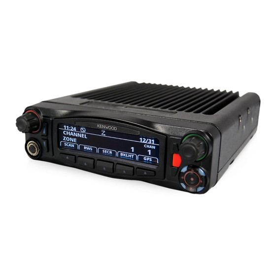
E C T I O N Controls & Display Section2 Standard Control Head The standard control head provides the primary controls, display, and speaker for the mobile radio. 2.1.1 Front Panel Controls Figure 2.1 shows the controls for the Viking VM600 Mobile radio. Figure 2.1 Front Panel Controls Programmable Buttons... -
Page 28: Option Buttons
Controls & Display ON-OFF /Volume - Pressing this control turns power ON and OFF (soft power down can be programmed as in Section 3.1.1.3), and rotating it sets the volume level. Select Switch - This switch can be pressed or rotated. An optional beep can be programmed to sound when it is pressed. -
Page 29: Display
Controls & Display 2.1.2 Display Figure 2.3 shows the front panel display. Note Radios are capable of displaying messages in English, French or Spanish. Figure 2.3 Front Panel Display Operating Mode Symbols Zone/Channel Select Indicators 10 - Character Alphanumeric Display Zone Status Channel... - Page 30 Controls & Display Table 2.2 lists the symbols used on the display to indicate various operating modes and status. Table 2.1 Standard Control Head Display Symbols Standard Control Head Display Symbols Operating Mode Symbols Unit (or Private) call mode active Busy (displayed when radio enters a busy transmit state) Monitor mode enabled Interconnect mode enabled...
-
Page 31: Lightning Control Head
Controls & Display Lightning Control Head An optional component for the Viking VM600 mobile radios is the Lightning Control Head illustrated in Figure 2.4. The Lightning Control Head offers superior readability and display options for the radio user. The control head can be fitted to both dash and remote mount mobile radio installations. -
Page 32: Front Panel Controls
Controls & Display 2.2.1 Front Panel Controls The Lightning Control Head front panel controls are illustrated in Figure 2.5. Figure 2.5 Light Control Head Controls Multi-function Indicator On-Off / Volume Select Zone/Channel Switch Display Switch Microphone One-Touch 4-Way Connection Programmable Buttons Navigation Pad On-Off Volume - This control has two actions: rotation and press. - Page 33 Controls & Display One-Touch Buttons - The control head has 8 one-touch buttons: two on the left of the display, five under the display, and an orange button on the right of the display. These buttons can be programmed with different radio functions. (See the Armada Programming manual for information on programming these button functions.) Figure 2.6 Lightning Option Buttons...
-
Page 34: Display
Controls & Display 2.2.2 Display The Lightning Control Head includes a highly readable display. The display is a mono- chrome display with 320 x 80 pixels. The display supports both the Classic Single Line display mode or enhanced Dual Line functionality. In Classic Single Line mode, display will have primary fields corresponding to the fields available on the mobile Viking control head, with the addition of the soft menu keys. - Page 35 Controls & Display Lightning Control Head Symbols (Continued) The current channel is the priority 2 channel in the enabled scan list (only when scan is on or when in scan edit mode) Interconnect mode enabled Private call mode enabled Radio is in Roaming mode P25 data context enabled (radio is ready for data operations) P25 data channel grant (radio is operating on a data channel) Site lock mode...
-
Page 36: Rear Panel Connectors
Controls & Display Rear Panel Connectors The mobile rear panel connectors are shown in Figure 2.8. These are applicable to both the Standard and Lightning control heads. Figure 2.8 Rear Panel Connectors Antenna DC Power Accessory DC Power - Connection point for the nominal 12-volt, negative ground power source (see Figure 2.8). -
Page 37: Dual Controls & External Speaker
Dual Controls & External Speaker Section3 Dual Control Configurations The Viking VM600 series mobile radio is available in two dual-control configurations, each with different programming and setup requirements: - Dash-mount radio with a remote mount control head - Remote-mount radio with two remote control heads Figure 3.1... -
Page 38: Remote Conversion Kit 250-5300-002
Dual Control Configurations Section 3 - Dual Controls & External Speaker Both dual control configurations can be configured and ordered as a complete kit. Existing Viking mobiles can also be converted to dual control configurations by the purchase of accessory kits, as described in the EFJohnson Subscriber Radio Accessories Catalog. Contact your EFJohnson Sales Representative for additional information. -
Page 39: Hardware Setup
Dual Control Configurations Section 3 - Dual Controls & External Speaker 3.1.3 Hardware Setup When shipped, the dual remote-mount configuration consists of a dash-mount radio, a remote control head, a conversion kit for the second control head, and required cabling. Upon receipt, the installer must convert the dash-mount mobile radio into a remote-mount configuration using instructions contained in the installation manual (part number 004- 5300-73001) which is supplied with the unit. -
Page 40: Programming Microphone Gain Settings
Dual Control Configurations Section 3 - Dual Controls & External Speaker Figure 3.3 Programming Microphone Gain Settings Removal of either control head will affect system performance. If there is a need to later convert the system to a single control head application, Armada must be used to un-check the "Dual Remote Control Head Gain"... -
Page 41: Master / Slave Programming
Dual Control Configurations Section 3 - Dual Controls & External Speaker 3.1.6 Master / Slave Programming In both dual control configurations, either control head can be designated as the Master and the other as the Slave. The Master control head controls the volume of its internal speaker and any external speakers that are connected to the radio's 8-pin accessory connector (see installation manual for connection details). -
Page 42: Dual Control Operation
Dual Control Configurations Section 3 - Dual Controls & External Speaker 3.1.7 Dual Control Operation 3.1.7.1 Power On/Off The power switching in dual configurations is such that either control head can switch the radio on, but both control heads must be off to turn the radio off. If the power button on both control heads is pressed, then the power button on both control heads must be pressed again to turn the radio off. -
Page 43: External Speaker
An optional 4 ohm, 15 watt external speaker is available from EFJohnson (Part No. 250- 0151-006). This can be used to enhance radio audio or to provide primary audio for a remote-mount radio. Refer to the Viking VM600 Series Mobile Radio Installation guides for additional installation information. - Page 44 External Speaker Section 3 - Dual Controls & External Speaker To re-enable the internal speaker, proceed as follows: 1 Power up the mobile radio 2 Press buttons F2 and F5 at the same time, and release (see Figure 3.4). 3 Rotate the Select knob, until display reads "SPKR ENABL" 4 After a short time-out period, display will read "CYCLE PWR"...
-
Page 45: General Operation
E C T I O N General Operation Section4 Basic Operation 4.1.1 Turning Power ON and Setting Volume Power is turned ON and OFF by pressing the ON-OFF /Volume knob. When power is turned ON, the radio goes through a self test. When that is successfully completed, software version, unit ID, zone, then channel are briefly displayed (except when a conventional analog channel is selected), a tone sounds (if tones are enabled), and the radio is ready for normal operation. -
Page 46: Setting Volume Level
General Operation If the Radio ID feature is enabled, the radio will display the Radio ID alias in place of the Self Test message during startup. Radio ID identifies the personality file used to program the radio, the service area for which the radio is programmed, or functional grouping for which the radio is programmed. -
Page 47: Power-Up Password
General Operation The user can power the radio completely down by pressing the option button programmed for this purpose (F2 or F6). If the user presses the ON/OFF/Volume knob while soft is in effect, the radio returns to full power up operation. 4.1.2 Power-Up Password The power-up password feature prevents unauthorized use of the radio by requiring that an... -
Page 48: Password Entry Procedure
General Operation 4.1.2.4 Password Entry Procedure When a password is requested, it is entered as follows: • Rotate and press the Select switch. A single beep sounds when the switch is pressed (if that option is selected) 4.1.2.5 User (Power-On) Passwords Separate Download (write) and Upload (read) passwords can be programmed to prevent unauthorized downloading or uploading of radio programming parameters. -
Page 49: Speaking Into The Microphone
General Operation 4.1.3 Speaking into the Microphone For best results, hold the microphone about 1-2 inches from your mouth and speak at a normal conversational level. Do not shout since it distorts your voice and does not increase range. Note If excessive background noise consistently interferes with communications, Microphone Sensitivity should be adjusted (using Armada). -
Page 50: Zone / Channel Display And Select
General Operation 4.1.6 Zone / Channel Display and Select Zone / Channel Display and Select operate as follows: 4.1.6.1 Zone / Channel Display The selected zone is shown on the radio display (Figure 4.1). When selected by the Zone/ Channel switch (see Section 4.1.6.3), the select bar will display above the Zone Number. In addition, the alias text identifier for the selected zone will be shown on the display screen. -
Page 51: Channel Lock Option
General Operation Channel alias can be a combination of zone and channel aliases. With conventional channels, the channel frequency may be displayed instead of the alias if the Display Information option switch is programmed (see Section 6.8). Figure 4.2 Channel Display Channel Select Indicator Channel Identifier Alias Zone... -
Page 52: 54-Channel/16-Zone Feature
General Operation Rotating the Select switch clockwise increases the zone or channel and rotating it counterclockwise decreases the zone or channel number. A single beep sounds when the channel is changed (if that option is enabled). After the highest zone or channel is displayed, wrap-around to the lowest zone or channel occurs and vice versa. -
Page 53: Favorite Zone Selection
General Operation For example, Zone 1/Channel 16 is selected by Channel 16, and Zone 2/Channel 16 is selected by Channel 32. Seq. Ch. No. Zone Channel 1 - 16 1 - 16 17 - 32 1 - 16 33 - 48 1 - 16 Proceed as follows to select channels using this mode: 1 Enable the direct Channel Select mode selecting it via the menu or by pressing the... -
Page 54: Setting Squelch Control
General Operation A “Favorites” button in the Viking VM600 allows the user to add channels to the Favorite Zone. If The Favorite Zone is enabled, the user has the ability to change the channels that are in his favorites list, as follows: 1 Select the zone / channel to be placed into Favorites, using the zone/channel selectors. -
Page 55: Preventing Vehicle Battery Discharge
General Operation 4.1.10 Preventing Vehicle Battery Discharge In the standby mode (power on, not transmitting), radio power consumption is relatively low. Therefore, you can probably leave the radio ON for one or two days without operating the vehicle and the battery should not become seriously discharged. However, if the outdoor temperature is low enough to significantly decrease battery capacity, the radio should be turned OFF when not in use. -
Page 56: Radio Service
General Operation 4.1.12 Radio Service If “UNPROGRAMD” is displayed, the cause can be any of the following: • An unprogrammed channel is selected. Select a programmed channel. • The selected channel is programmed for an option that is not installed or an error in programming was detected. -
Page 57: Operating Modes
General Operation Operating Modes Each selectable channel can be programmed for the conventional (analog or Project 25 digital), SMARTNET/SmartZone, or Project 25 digital trunked operating mode. For example, Zone 1/Channel 1 could be a conventional channel, Zone 1/Channel 2 a SMARTNET channel, and so on. -
Page 58: P25 Trunked Mode
General Operation SMARTNET and SmartZone operation and programming is very similar. Basically, SMARTNET operation is limited to a single repeater site and SmartZone operation allows automatic roaming between sites. SMARTNET/SmartZone features include roaming ™ (SmartZone only), telephone, private, and emergency calls, Call Alert , and messaging. -
Page 59: Systems, Channels, And Zones
General Operation • The P25 mode uses a system ID, Wide Area Communications Network (WACN) ID, and RF Subsystem ID (RFSS). The SmartZone mode does not use the WACN and RFSS IDs. • P25 Unit IDs can be 1-16,777,215 (000001-FFFFFF hex) and SmartZone Unit IDs can be 1-65,535 (0001-FFFF hex). -
Page 60: Zones
General Operation 4.2.4.3 Zones A zone is a collection of up to 16 channels of any type. For example, a zone could include 12 conventional channels and four SMARTNET channels. One use of zones may be to program the channels used for operation in a different geographical areas. The maximum number of zones is 32 or 54 depending on the option enabled. -
Page 61: Radio Wide Features
E C T I O N Radio Wide Features Section5 Radio wide features are features common to all operating modes. Option Buttons Six option buttons on the front panel (one is located to the left of the display) can be programmed to control a different set of functions for each of the three operating modes. - Page 62 Radio Wide Features The available functions in each mode are shown in Table 5.1. Table 5.1 Programmable Option Button and Menu Mode Functions X = Available in Mode: Project 25 Function Conventional Trunking SMARTNET SmartZone Menu Display Activate OTAP ACTV OTAP Alert tones On-Off TONES Auto Site Search...
-
Page 63: Menu Mode
Radio Wide Features Table 5.1 Programmable Option Button and Menu Mode Functions (Continued) X = Available in Mode: Project 25 Function Conventional Trunking SMARTNET SmartZone Menu Display Radio Wide Scan Select RW SCAN Rekey Request OTAR REKEY Remote Access (Pyramid RMT ACCESS Repeater) Repeater Talk-Around Select... -
Page 64: Time-Out Timer
Radio Wide Features Time-Out Timer The time-out timer disables the transmitter if it is keyed for longer than the programmed time. It can be programmed on each channel for times of 15 seconds to 3 minutes, 45 seconds or it can be disabled. If the transmitter is keyed continuously for longer than the programmed time, the transmitter is disabled, a continuous tone sounds, and “TX TIMEOUT”... -
Page 65: Alert Tone Select
Radio Wide Features Pressing the TX PWR switch toggles the power setting. The new level is flashed in the display when this switch is pressed as “HI POWER” or “LOW POWER”. If selectable power is not permitted on the current channel or system, the fixed power level is flashed and no power change occurs. -
Page 66: Horn Alert
Radio Wide Features Horn Alert The horn alert feature sounds an external alert such as the vehicle horn when certain calls are received. It is available if a Horn option switch is programmed and the proper connection has been made to the external alert. The horn alert output is pin 4 of the accessory cable, and an external driver circuit of some type is usually required. -
Page 67: Surveillance Mode
Radio Wide Features 5.10 Surveillance Mode If the Surveillance mode is programmed, the backlight, all alert tones, and front panel LED indicator can be disabled individually or totally, based on programming. The transmit/receive LED indicator, display and keypad backlight, and all alert tones can be disabled. -
Page 68: Scanning
Radio Wide Features 5.12 Scanning Scanning monitors the channels in the scan list for messages the radio is programmed to receive. When a message is detected, scanning stops and the message is received. Shortly after the message is complete, scanning resumes. If the microphone off-hook condition is detected (Hangup Box Monitor selected by programming), scanning stops and selective squelch (such as Call Guard CTCSS or NAC/ group ID detect) is disabled on conventional channels. -
Page 69: Radio Wide Scanning
Radio Wide Features • If the zone or channel is changed while scanning is selected, scanning continues on the same or a different scan list (see Section 5.13.1). Note Each SMARTNET/SmartZone and P25 trunked channel can be programmed so that scanning is automatically enabled when the channel is selected. -
Page 70: Nuisance Channel Delete
Radio Wide Features Conventional Operation - Transmissions can be programmed to always occur on the priority, selected, or receive channel (if applicable). Refer to Section 6.10 for more information. SMARTNET/SmartZone/P25 Trunked Operation - If scanning is halted to receive a message, programming determines if transmissions occur on the selected or active channel. -
Page 71: Scan Lists
Radio Wide Features 5.13 Scan Lists Priority and Radio Wide Scan lists can be programmed. 5.13.1 Priority Mode Scan Lists A scan list is simply the channels that are scanned when scanning is enabled. With all operating modes, as many priority scan lists as are required can usually be programmed (up to 255). -
Page 72: Editing A Priority Scan List
Radio Wide Features 5.13.1.3 Editing a Priority Scan List If the SCN ED (Scan Edit) option switch is programmed, priority scan lists can be user edited as follows (all operating modes). This option is also selectable via the menu. Changes are permanent (cycling power does not reselect a default condition). Proceed as follows: 1 Make sure that both priority and radio wide scanning are OFF (the rotating icon is... -
Page 73: Radio Wide Scan List
Radio Wide Features 5.13.2 Radio Wide Scan List With radio wide scanning, there is only one scan list available regardless of the type of channel selected. This list is user programmable and can include up to 16 channels of any type. -
Page 74: Global Positioning System (Gps)
Radio Wide Features 5.14 Global Positioning System (GPS) If this feature is enabled, GPS data can be received from satellites when a GPS receiver is attached to the serial port of the radio. GPS data can be viewed using P25, Conventional, MultiNet, and SMARTNET/SmartZone Systems. -
Page 75: Sending Gps Data
Radio Wide Features 5.14.2 Sending GPS Data The radio can send GPS data in conventional digital mode only. Refer to paragraph 6.16 for more information. 5.15 Over the Air Programming OTAP is an “Over the Air” programming feature for the subscriber parameter (code plug) files. -
Page 76: Otap Transfer Times
Radio Wide Features and any buttons/menu items must be programmed in Armada prior to beginning an OTAP procedure if an action other than the default “Prompt” is desired. The radio must also be registered with the data router for an OTAP procedure to take place. - If the radio has undergone a successful download, by selecting the menu item or pressing the button, the radio displays the message “ACTIVATING”... -
Page 77: Conventional Features
E C T I O N Conventional Features Section6 Conventional mode features are radio features unique or used only when operating in conventional mode. Monitoring Before Transmitting With conventional operation, you may need to manually monitor the channel before transmitting to make sure that it is not being used by someone else. If you were to transmit while someone else was using the channel, you would probably disrupt their conversation. -
Page 78: Monitor Mode
Conventional Features Busy Indicator - With scanning disabled, note if the multi-function indicator on the front panel is steady green. If it is green, a carrier is being detected, so the channel may be busy. If it is not, the channel is not being used and a call can be transmitted. Monitor Mode - There may be times when the busy indication is displayed even though no one is using the channel. -
Page 79: Busy Channel Lockout
Conventional Features Busy Channel Lockout The Busy Channel Lockout (also called Transmit Disable on Busy) feature automatically disables the transmitter if the channel is busy when the PTT switch is pressed. When the transmitter is disabled by this feature, “BUSY” is displayed, a busy tone sounds, and the transmitter is disabled. -
Page 80: Call Guard Squelch Enable / Disable
Conventional Features 6.4.1 Call Guard Squelch Enable / Disable The SEL SQ option switch (if programmed) can be used to disable receive Call Guard squelch (Normal/Selective Squelch) on analog channels or group ID code detection on P25 channels. This option is also selectable via the menu. When selective squelch is disabled, “SQ NORMAL”... -
Page 81: Disable Call Guard
Conventional Features 6.4.4 Disable Call Guard The Disable Call Guard feature option lets the radio disregard any CTCSS/DCS or NAC/ Talkgroup information on the current channel. This programmable feature is best described as a monitor mode with no white noise. In analog it is functionally the same as turning the squelch mode to "normal."... -
Page 82: Penalty Timer
Conventional Features 64. The code number and actual code are alternately displayed (NACs are displayed in hexadecimal). 2 To select the displayed code and return to the normal display, press the SQ LIST (Squelch Code Select) switch again. 3 To check which code is selected, press the SQ LIST option switch once to display the current selection and then again to return to normal operation. -
Page 83: Repeater Talk-Around
Conventional Features Repeater Talk-Around Normally, all transmissions go through a repeater which usually increases range. However, there may be times when a radio is out of range of the repeater and therefore unable to talk to anyone even though the radio being called is only a short distance away. To allow communication in this situation, repeater talk-around can be selected. -
Page 84: Emergency Alarm And Call
Conventional Features Emergency Alarm and Call Emergency Alarms and Calls are separate functions that can be individually enabled or disabled on each analog and P25 conventional system. The Emergency option switch (or menu selection) is required for these functions. Emergency Alarms and Calls are transmitted on the global (radio wide) emergency zone/channel if one is programmed and a smart console with message receiving capabilities is used. -
Page 85: Emergency Call Alert
Conventional Features 6.9.2 Emergency Call Alert This feature notifies a user when an emergency call is being made on their selected P25 Conventional or P25 Trunking Talkgroup. The radio should also be programmed with an “Emergency Clear” button. If an emergency call is received by the radio on the selected channel, the emergency alarm ACK tone will sound (five consecutive tones), and the Emergency Received message will display, followed by the unit ID of the emergency radio. -
Page 86: Conventional Mode Channel Scanning
Conventional Features 1 If required, select a channel of a system on which Emergency Calls are enabled and press the EMER option switch. The Emergency Call is then sent as described in Section 6.9.1 if applicable. 2 If the preceding Emergency Hot Mic feature is enabled, the call is automatically transmitted without pressing the PTT switch. -
Page 87: Transmitting In Scan Mode
Conventional Features 1 With scanning OFF, press and hold the SCAN option switch until a tone sounds (or use menu selection). Scanning is OFF when the rotating is not indicated in the right status display. If required, turn scanning OFF by briefly pressing this switch. If the SCAN option switch is pressed while scanning, Nuisance Channel Delete described in Section 5.12.5 is performed. -
Page 88: Changing The Priority Channel
Conventional Features Note Priority channel sampling is not available when receiving analog encrypted (DES) calls. In addition, the priority channel is not scanned if the active channel is an analog channel on the same frequency as the priority channel and is programmed with CTCSS/DCS squelch control. -
Page 89: Talkgroup Scanning
Conventional Features 1 Make sure that both priority and radio wide scanning are OFF (the rotating icon is not indicated in the right status display). 2 Select the channel that you want to be the priority channel using the Select switch in the normal manner. -
Page 90: Placing A Standard Conventional Call
Conventional Features 6.11.1 Placing a Standard Conventional Call To place a standard conventional call, proceed as follows: 1 Turn power ON and set the volume as described in Section 4.1.1. Select the channel programmed for the radio you want to call (see Section 4.1.6.3). 2 Monitor the channel automatically or manually as described in Section 6.1. -
Page 91: Single Tone Encoder
Conventional Features When an emergency alarm or call is placed, this ANI signaling is replaced by the Emergency DTMF ID (see Section 6.9). Refer to Section 6.12.3 for information on MDC1200 ANI. 6.12.1 Single Tone Encoder The radio will transmit and send a single tone as programmed in Armada. Single tone ANI provides call-in signaling, but does not provide identification of individual units, i.e. -
Page 92: Project 25 Mode Features
Conventional Features 6.13 Project 25 Mode Features The following features are unique to conventional P25 channels. 6.13.1 Digital Unit ID Each radio that operates on Project 25 (digital) channels is programmed with an up-to- eight-digit unit ID. This ID is unique for each radio and can be any number from 1- 16,777,215. -
Page 93: Efjohnson System Automatic Registration
Conventional Features 6.13.5 EFJohnson System Automatic Registration When used in a EFJohnson P25 conventional infrastructure radio system, an option on the radio can be programmed to provide additional identifying information to the system upon receipt of a dynamic data registration request. If the "EFJ Affiliation" option is enabled, the subscriber unit will transmit its current talkgroup and mobile computer IP address to the system in addition to its unit ID during a dynamic data registration request. -
Page 94: P25 Unit Calls
Conventional Features that option is enabled). If talkgroup selection has been disabled on the channel by programming, the talkgroup does not change, “NO LIST” is displayed, and a tone sounds. 6.13.7 P25 Unit Calls Unit calls (also called Individual Calls) can be placed to a specific radio on Project 25 channels using the Unit Call option switch (if programmed) or by menu selection. -
Page 95: Access / De-Access Codes
Conventional Features • List only - Telephone numbers can be selected from a preprogrammed list only (direct entry as follows is not allowed) • Unlimited - Telephone numbers can be selected from a list and also dialed directly entered using the front panel controls or the keypad on the HHC. All models have the capability to place telephone calls by recalling the number from a list or dialing it using the front panel controls or using the Handheld Control Unit (HHC) telephone keypad. -
Page 96: Answering A Telephone Call
Conventional Features 7 If using the front panel controls, enter the telephone number by rotating and pressing the Select switch. The 0-9, , #, and P (pause) characters can be entered (# is displayed as a “+”). Numbers up to sixteen digits (including pauses) can be entered, and the number scrolls to the left in the display so that the eight right-most digits are always displayed. -
Page 97: 6.13.10 Call History
Conventional Features displayed. Press the PTT switch and respond. One of the following conditions then occur: - If the radio being called is on the air, ringing is heard until the called party answers or for 20 seconds, whichever occurs first. If no answer occurs within 20 seconds, a continuous tone sounds and “NO ANS”... -
Page 98: 6.13.11 Messaging
Conventional Features 6.13.11 Messaging The messaging feature allows preprogrammed messages to be sent to a dispatcher on P25 channels. Up to 16 messages can be preprogrammed, and they are identified by an alias. If a MSG (Message) option switch is programmed, messages are sent as follows: 1 Momentarily press the MSG option switch (or select the option via the menu). -
Page 99: 6.13.13 P25 Packet Data
Conventional Features 6.13.13 P25 Packet Data See Section 9 for information on data functions and services. 6.14 Keypad Programming Since keypad programming is permitted by Federal Government users only, only Federal models of this radio can be programmed with this feature. It is then available only if it has been enabled by factory programming and a conventional mode option switch is programmed for the “Keypad Programming”... -
Page 100: Zone Password
Conventional Features Press the Select switch to select the displayed parameter. A single beep sounds when the switch is pressed (if that option is enabled). Press the PROG option switch from one of the main menus to exit keypad programming or from other menus to exit back one level. A flowchart showing the keypad programming mode menu structure is located Figure 6.1. -
Page 101: Zone Change Parameter
Conventional Features When an attempt is made to select a system or channel parameter in a password protected zone, “PASSWORD” is flashed. The password is always eight digits long and is entered using the same procedure as used for the power-up password described in Section 4.1.2. After the password is entered, system and channel parameters for that zone can be reprogrammed normally. -
Page 102: Channel Parameters
Conventional Features When the desired value is displayed, store it by pressing the Select switch. A single beep sounds when the switch is pressed (if that option is enabled). TX TIMER - Selects the transmit time-out timer. Rotate the Select switch to decrement/increment the timer in 15-second steps from 0-225 or disable it by selecting 0 seconds. - Page 103 Conventional Features desired code type (CTCSS analog or DCS digital). If an invalid code is entered, a beep sounds, “INVALID” is briefly displayed, and the editing mode continues to be selected. TX CODE - Selects the transmit codes the same as RX CODE above. NAC Squelch Control (Project 25 Channel).
-
Page 104: Text Messaging
Conventional Features Note The channel spacing is not set with P25 channels because it is always narrow, and the squelch cannot be changed because the setting is critical for proper receiver operation. SQ ADJUST (Analog Only) - Changes the preset squelch setting on that channel. The default setting is “0”... -
Page 105: Receiving A Text Message
Conventional Features If “Set R to R” is disabled: • A text message can be received from radios on a digital channel with a repeater if PCTextMessage is connected to that repeater (all radios must be dynamically registered to the repeater) •... -
Page 106: Sending Global Positioning System (Gps) Data
Conventional Features 3 To view the message text, press the Select knob. Note Text messages are retained only while the radio is powered up. If power is removed, all text message data is lost. 6.16 Sending Global Positioning System (GPS) Data If the radio is setup for operation with a GPS receiver (see paragraph 5.14), GPS data can be sent to a properly configured repeater (digital conventional only). -
Page 107: Sending Gps Data In Response To System Request
Conventional Features 6.16.3 Sending GPS Data in Response to System Request If so configured, the radio accepts P25 data requests for GPS data, and responds (over the air or through Ethernet) with the current GPS data. Viking VM600 Mobile Radio Operating Manual 6-31 Draft 4/29/2014... - Page 108 Conventional Features 6-32 Viking VM600 Mobile Radio Operating Manual Draft 4/29/2014...
-
Page 109: Smartnet / Smartzone / P25 Trunked Features
E C T I O N SMARTNET / SmartZone / P25 Section7 Trunked Features The features described in this section are radio features unique to these modes of operation. Analog and Digital Operation Either analog or digital operation can be selected for communication on SmartZone traffic channels. -
Page 110: Radio Info Button
SMARTNET / SmartZone / P25 Trunked Features 7.2.1 Radio Info Button Pressing the Radio Info button (if programmed) or selection of the menu parameter allows the user to display the ID programmed for the currently selected protocol. If the radio is on a digital conventional channel, it shows the digital conventional ID. - Page 111 SMARTNET / SmartZone / P25 Trunked Features - If in the secure mode and your radio is not programmed with the proper encryption key, “KEYFAIL” is displayed and the call must be made in the clear mode or the proper key must be programmed. - If the busy tone sounds and “BUSY”...
-
Page 112: Receiving A Standard Group Call
SMARTNET / SmartZone / P25 Trunked Features 7.3.2 Receiving a Standard Group Call Calls are received on only the talkgroup and/or announcement group programmed for the selected channel (with scanning disabled). When the selected channel is programmed with both Talk and Announcement groups, only the Talk and Announcement group IDs are detected. -
Page 113: Placing An Enhanced Private Conversation Call
SMARTNET / SmartZone / P25 Trunked Features • Unlimited - Unit IDs can be selected from a list and also dialed directly using the front panel controls or the keypad on the HHC. 7.4.1 Placing an Enhanced Private Conversation Call To recall from a list: 1 Momentarily press the Private Call option switch or select the menu parameter. -
Page 114: Placing A Standard Private Conversation Call
SMARTNET / SmartZone / P25 Trunked Features - If your radio or the called radio is inhibited or not programmed to make this type of call or for the requested secure mode, “RSPNS ONLY” is displayed and an alert tone sounds. -
Page 115: Receiving A Private Call (All Types)
SMARTNET / SmartZone / P25 Trunked Features - If the radio system is busy, four low tones sound and “BUSY” is displayed. When the system is no longer busy, the call back tone (four beeps) is heard and the channel is automatically acquired. -
Page 116: Placing A Telephone Call
SMARTNET / SmartZone / P25 Trunked Features • List only - Telephone numbers can be selected from a preprogrammed list only (direct entry as follows is not allowed). • Unlimited - Telephone numbers can be selected from a list and also dialed directly entered using the front panel controls or the keypad on the HHC. -
Page 117: Receiving A Telephone Call
SMARTNET / SmartZone / P25 Trunked Features Each time the PTT switch is released, a go-ahead tone is sent to the landside party to indicate when they can respond. To dial a number after the connection is made, press the PTT switch and dial the number using the keypad on the HHC. If the selected telephone number is not valid, “INVALID”... -
Page 118: Answering A Page
SMARTNET / SmartZone / P25 Trunked Features 7.6.1 Answering a Page To answer a Page: 1 When a page is received, five beeps sound and “PAGE RCVD” is displayed. The ID of the radio paging you is stored as the last ID received. 2 To clear or ignore the page, press any option switch. -
Page 119: Messaging
SMARTNET / SmartZone / P25 Trunked Features - If the system received the page but the called mobile is not on the air, a single beep sounds and “NO ACK” is displayed six seconds after the PTT switch is pressed. Auto exit then occurs. -
Page 120: Emergency Alarm And Call
SMARTNET / SmartZone / P25 Trunked Features - If five beeps sound and “ACK RCVD” is displayed, the status was received and acknowledged by the system. - If after five tries the message is not acknowledged, a tone sounds and “NO ACK” is displayed. -
Page 121: Emergency Call Alert
SMARTNET / SmartZone / P25 Trunked Features 2 When the emergency alarm is acknowledged, “ACK RCVD” is briefly displayed and the emergency acknowledge tone (five beeps) sounds. Silent operation may also be programmed in which case no tone sounds and there is no indication that an acknowledgment occurred. -
Page 122: Emergency Hot Mic
SMARTNET / SmartZone / P25 Trunked Features 7.9.3.1 Emergency Hot Mic If Emergency Hot Mic has been enabled for emergency calls, automatic transmitting occurs with microphone audio unmuted without having to manually press the PTT switch. The automatic transmit period is programmed for 10-120 seconds in ten-second intervals. If the “Increment by 1”... -
Page 123: Failsoft Operation
SMARTNET / SmartZone / P25 Trunked Features 5 To exit this mode, cycle radio power or press and hold the Emergency switch. 7.10 Failsoft Operation If a failure occurs in the SMARTNET/SmartZone or P25 Trunked system so that it cannot be used, the system directs the radio to automatically enter the failsoft mode. - Page 124 SMARTNET / SmartZone / P25 Trunked Features • When responding to calls in the scan mode, the programming of the Talkback Scan parameter determines if a response always occurs on the talkgroup of the call (Active Group) or the Selected Group if they are different. Transmissions at other times always occur on the selected talkgroup.
-
Page 125: Priority Talkgroup Sampling
SMARTNET / SmartZone / P25 Trunked Features 7.11.1 Priority Talkgroup Sampling One talkgroup in the scan list can be designated a priority talkgroup by programming or it can be the selected talkgroup. When scanning, messages on a non-priority talkgroup are interrupted by messages on the priority talkgroup. -
Page 126: Dynamic Regrouping
SMARTNET / SmartZone / P25 Trunked Features 3 To select another list, “PROGRAMMED”, or “NO LIST”, rotate the Select switch. When the desired list is displayed, select it and exit this mode by pressing the Scan List option switch again. 7.12 Dynamic Regrouping The dynamic regrouping feature allows a dispatcher to change the current talkgroup or... -
Page 127: Smartzone And P25 Trunking Unique Features
SMARTNET / SmartZone / P25 Trunked Features 7.13 SmartZone and P25 Trunking Unique Features ® SmartZone and P25 Trunked modes can provide access to single or multi-site systems. The P25 Trunked mode can provide access to a single trunked site or roaming between several trunked sites. -
Page 128: Determining Current Site And Searching For A New Site
SMARTNET / SmartZone / P25 Trunked Features 7.13.3 Determining Current Site and Searching for a New Site To display the RSSI level of the current site, press the SEARCH option switch. The display then indicates the current site number as “SITE xx” and the RSSI (Receive Signal Strength Indicator) signal level as “RSSI xx”. -
Page 129: P25 Wide Area Scan
SMARTNET / SmartZone / P25 Trunked Features With the Zone Fail Site Lock feature enabled, the radio continues to roam normally when the system zone controller is active. However, if the zone controller fails, this is detected and the Zone Fail Site Lock mode is entered. The only site the radio is then allowed to operate on is its home site. -
Page 130: 7.13.10 P25 Wide Area Scan
SMARTNET / SmartZone / P25 Trunked Features The problem with this operation is that every time a different talkgroup is selected, the access permission may be different and a different site may need to be accessed. This could result, in a worst case, in a delay of up to 30 seconds in finding a new site. This could occur if there are no valid sites for the new talkgroup in the dynamic site list. -
Page 131: 7.13.11 Radio Information
SMARTNET / SmartZone / P25 Trunked Features 7.13.11 Radio Information Various radio information can be viewed on the radio display. The "Radio Info" radio button or menu item is selected to view this information. When selected, the information will scroll across the radio display. You can pause, and move the text back and forth using the same controls as you would for text messaging. - Page 132 SMARTNET / SmartZone / P25 Trunked Features 7-24 Viking VM600 Mobile Radio Operating Manual Draft 4/29/2014...
-
Page 133: Secure Communication (Encryption)
E C T I O N Secure Communication (Encryption) Section8 This radio may be equipped to provide secure communication on some or all channels. This feature encrypts the voice so that it can be understood only by someone using a radio equipped with a similar encryption device and encryption codes. -
Page 134: Aes (Advanced Encryption Standard)
Secure Communication (Encryption) 8.1.2 AES (Advanced Encryption Standard) An encryption standard called AES is replacing DES-OFB encryption on digital (P25) channels. It uses a 128-, 192-, or 256-bit encryption key instead of the 64-bit key used with DES. EFJohnson Technologies radios currently support only 256-bit AES keys. The type of encryption (DES or AES) is determined by the type of encryption key that is loaded (see Section 8.2), and not by the Armada programming software. -
Page 135: Key And Algorithm Ids
Secure Communication (Encryption) If an attempt is made to transmit a secure message without loading the corresponding key, “KEY FAIL” is displayed. The message must then be transmitted in the clear mode (this is possible only if the channel is strapped to “switchable”) or the key must be loaded. 8.2.1 Key and Algorithm IDs Each encryption key is programmed with a Key ID (also called Logical ID). -
Page 136: Maintaining Keys In Memory
Secure Communication (Encryption) or digital encryption, and can also be used with the with the Motorola KVL-3000 Plus. With this mode, keys are loaded into a SLN (Storage Location Number), typically from 0-4095. The Keys Table must then be programmed to link channel PIDs to a specific SLN. -
Page 137: Encryption Key Erase
Secure Communication (Encryption) 8.2.5 Encryption Key Erase A KY CLR option switch can be programmed that allows the user to permanently erase all stored keys. If OTAR TEK and KEK keys are stored, all keys of both types are erased. This function can be used to ensure that unauthorized encrypted calls can no longer be placed or received by a radio. -
Page 138: Analog Receive Mode Options
Secure Communication (Encryption) If the channel has been strapped “Clear” and the option switch selects the “Secure” mode on power up and a transmission is attempted, “CLEAR ONLY” is displayed and transmitting is disabled. Likewise, if the channel is strapped “Secure” and the option switch selects the “Clear”... -
Page 139: Security Settings Override
Secure Communication (Encryption) Security Settings Override The default security settings that determine how encryption keys are used for talkgroups and channels can be changed for different operating modes. 8.4.1 Conventional (P25) Talkgroup Security Override On conventional digital (P25) channels, the encryption strapping mode and PID are programmed on a per talkgroup basis similar to the trunked modes (SMARTNET/ SmartZone/P25 Trunked). -
Page 140: Channel With Both A Talkgroup And Announcement Group Specified
Secure Communication (Encryption) 8.4.2.3 Channel with both a Talkgroup and Announcement Group Specified For a Talkgroup Call if the override security settings feature is enabled, then the override parameters will be used. If the override feature is not enabled, then the talkgroup parameters will be used. - Page 141 Secure Communication (Encryption) 1. The talkgroup is 1, the any key option is disabled, and the channel is secure and uses key 1. 2. The talkgroup is 2, the any key option is disabled, and the channel is secure and uses key 2.
-
Page 142: Over-The-Air Rekeying (Otar)
Secure Communication (Encryption) Over-The-Air Rekeying (OTAR) OTAR stands for “Over-The Air-Rekeying”. This is the process of sending encryption keys and related key management messages over-the-air to specific radios. The advantage of OTAR is that it allows these keys to be quickly and conveniently updated when necessary. -
Page 143: Key Management Facility
Secure Communication (Encryption) Notice that if all radios in a cryptonet are using traffic keys from the same active keyset, the keys contained in the inactive keyset of each radio can be replaced without disrupting encrypted communications. Once the keys in the inactive keyset are replaced for every radio in a given cryptonet, the radios can switch active keysets and start using the new keys. -
Page 144: Message Number Period (Mnp)
Secure Communication (Encryption) • Modifying keyset names • Deleting keys • Deleting all keys (zeroize) when a radio may be lost or compromised • Determining if a radio is on the air and reading key information • Changing individual and group RSIs •... - Page 145 Secure Communication (Encryption) Black - Refers to information that is encrypted. The opposite is “Red” which refers to unencrypted information. Common Key Encryption Key (CKEK) - This is a KEK common to a group of subscriber units which share the same encryption. These keys can be the DES or AES type.
- Page 146 Secure Communication (Encryption) Keyset Changeover - The process used to switch the active keyset setting on a subscriber unit to the currently inactive keyset so that the keys in the newly inactive keyset can be replaced without interrupting encrypted communication. Key Loader - Any type of device used to load encryption keys into a radio.
-
Page 147: Radio Setup For Encryption
Secure Communication (Encryption) Radio Setup For Encryption The following radio setup is required for encryption regardless of whether OTAR is used: Options Enabled - The desired encryption type must have been enabled at the factory (DES, DES-OFB, AES). To determine what options are enabled, use Armada. The following are set through Armada. -
Page 148: Programming By Keyloader
Secure Communication (Encryption) 8.6.0.2 Programming By Keyloader The following are the minimum parameters that need to be programmed in the radio to perform OTAR. It is not necessary to program a TEK but it is necessary that a UKEK be manually programmed to perform OTAR. -
Page 149: Otar Option Switches
Secure Communication (Encryption) OTAR Messages That Are Supported The following KMM Message IDs are recognized by or sent: CHANGE RSI 0x03 CHANGE RSI RESPONSE 0x04 KEYSET CHANGEOVER 0x05 KEYSET CHANGEOVER RESPONSE 0x06 DELAYED ACK 0x07 HELLO 0x0C INVENTORY 0x0D INVENTORY RESPONSE 0x0E MODIFY KEY 0x13... -
Page 150: P25 Trunking Icons
Secure Communication (Encryption) Clear/Secure Select - This enables and disables encryption regardless of whether OTAR is used. Refer to Section 8.3 for more information. Erase Keys - Erases all TEK and KEK keys contained in the radio. Key Select - This allows a different key to be selected for the current channel or group (conventional channels only). - Page 151 Secure Communication (Encryption) - The data channel icon goes out (once the radio returns to a control channel), but the data context icon stays on. If the data context icon is not on, you do not have an SNDCP context (i.e., you are not data registered).
- Page 152 Secure Communication (Encryption) 8-20 Viking VM600 Mobile Radio Operating Manual Draft 4/29/2014...
-
Page 153: Data Features
E C T I O N Data Features Section9 Advances in digital communications allows for new data features and services using the radio link. This section describes the data features and services available for the Viking VM600 radio. P25 Packet Data P25 packet data transmission capability is available with Viking VM600 mobile radios. -
Page 154: P25 Trunking Data Services
Data Features P25 Trunking Data Services P25 Trunking supports data service on a P25 Trunking system using an EF Johnson Technologies radio and a portable computer. The radio communicates with the computer over the P25 Mobile Data Peripheral (MDP) Interface, which uses an RS232 hardware interface at 9600 bits/s. -
Page 155: Interface Connection
Data Features Frame Sync Seek Period - Selects the amount of time the radio listens for a frame sync sequence before a packet is transmitted. Times are 0 to 5000 msec., in increments of 50 msec. The default is 750 msec. Tx Short Random Range - Selects the maximum amount of time the radio waits to transmit once the first qualified FS is received indicating the channel is clear. -
Page 156: Ppp Link Establishment
Data Features 9.2.4 PPP Link Establishment To begin data transmissions from an application running on a portable computer, a data connection must first be established between the mobile computer and the radio (with data capability enabled). This is accomplished by creating a new connection using the Microsoft Windows Operating System. - Page 157 Data Features 2 Click Create a new connection link.The New Connection Wizard screen appears (Figure 9.2). Figure 9.2 New Connection Wizard Screen Viking VM600 Mobile Radio Operating Manual Draft 4/29/2014...
- Page 158 Data Features 3 Click Next. The Network Connection Type screen appears (Figure 9.3). Figure 9.3 Network Connection Type Screen Viking VM600 Mobile Radio Operating Manual Draft 4/29/2014...
- Page 159 Data Features 4 Select Set up an advanced connection, then click Next. The Advanced Connection Options screen appears (Figure 9.4) Figure 9.4 Advanced Connection Options Screen 5 Select Connect directly to another computer, then click Next. The Host or Guest screen appears (Figure 9.5).
- Page 160 Data Features Figure 9.5 Host or Guest Screen Viking VM600 Mobile Radio Operating Manual Draft 4/29/2014...
- Page 161 Data Features Figure 9.6 Connection Name Screen Viking VM600 Mobile Radio Operating Manual Draft 4/29/2014...
-
Page 162: Select A Device Screen
Data Features 7 In the Computer Name frame, type the name for the connection. Then click Next. The Select a Device screen appears (Figure 9.7). Figure 9.7 Select a Device Screen 8 From the Select a device pull-down list, select the communications port to use to connect the cable from the radio to the computer. - Page 163 Data Features Figure 9.8 Connection Availability Figure 9.9 Completing New Connection Wizard Screen Viking VM600 Mobile Radio Operating Manual 9-11 Draft 4/29/2014...
- Page 164 Data Features 10 Click Finish. The new connection is established (and should be in the network connection folder). The Connect Radio screen appears (Figure 9.10). Figure 9.10 Connect Radio Screen 11 Click Properties. The Radio Properties screen appears (Figure 9.11). 12 Under the General tab, click Configure.
- Page 165 Data Features Figure 9.11 Radio Properties Screen: General Tab 13 Click OK. The Modem Configuration screen appears (Figure 9.12). Viking VM600 Mobile Radio Operating Manual 9-13 Draft 4/29/2014...
- Page 166 Data Features Figure 9.12 Modem Configuration Screen 14 From the Maximum Speed pull-down list, select 9600. Leave all other options unchecked, and click OK. The Radio Properties screen returns (Figure 9.13). 9-14 Viking VM600 Mobile Radio Operating Manual Draft 4/29/2014...
- Page 167 Data Features Figure 9.13 Radio Properties Screen: Options Tab 15 Under the Options tab, ensure that the box for Prompt for name and password certificate, etc. is unchecked. Then select the Networking tab (Figure 9.14). 16 Under the Networking tab, ensure that the following boxes are unchecked: - File and printer sharing for Microsoft Networks - Intel Wireless Connection Agent - Deterministic Network Enhancer...
- Page 168 Data Features Figure 9.14 Radio Properties Screen: Networking Tab 17 Ensure that the box for Internet Protocol (TCP/IP) is checked. Then click Properties.The Internet Protocol (TCP/IP) Properties screen appears (Figure 9.15). 9-16 Viking VM600 Mobile Radio Operating Manual Draft 4/29/2014...
- Page 169 Data Features Figure 9.15 Internet Protocol (TCP/IP) Properties Screen 18 Select Obtain an IP address automatically, then click Advanced. The Advanced TCP/ IP Settings screen appears (Figure 9.16). Viking VM600 Mobile Radio Operating Manual 9-17 Draft 4/29/2014...
- Page 170 Data Features Figure 9.16 Advanced TCP/IP Settings Screen 19 Ensure that the box for Use default gateway on remote network is unchecked. Then click OK. The Internet Protocol (TCP/IP) Properties screen returns (Figure 9.17). 9-18 Viking VM600 Mobile Radio Operating Manual Draft 4/29/2014...
- Page 171 Data Features Figure 9.17 Internet Protocol (TCP/IP) Properties Screen 20 Click OK. The Radio Properties screen returns (Figure 9.18). 21 Click Cancel. The configuration of the connection between the radio and the portable computer is complete. Viking VM600 Mobile Radio Operating Manual 9-19 Draft 4/29/2014...
-
Page 172: Connection And Testing
Data Features Figure 9.18 Radio Properties Screen: Networking Tab 9.2.4.1 Connection and Testing To connect the computer and radio and test the connection perform the instructions in the following paragraphs. 9.2.4.1.1 Connection To connect the computer and radio, right click on the network icon. The Connecting Radio window (Figure 9.19) appears, and remains until the connection is made. - Page 173 Data Features Figure 9.19 Radio Connection Window 9.2.4.1.2 PPP Link Test Further verification that the link is working correctly an be made by “pinging” the subscriber radio from the mobile computer: 1 Activate the Command Prompt screen from the Accessories pull-down list of the Start menu (see Figure 9.20).
- Page 174 Data Features Figure 9.21 Command Prompt Screen: Replies to Successful “Ping” 9-22 Viking VM600 Mobile Radio Operating Manual Draft 4/29/2014...
-
Page 175: Tones & Error Messages
E C T I O N Tones & Error Messages Section10 10.1 Supervisory Tones Supervisory Tones are described as follows: Single Beep (Alert Tone) • Power was turned ON and a successful power-up sequence occurred (see Section 4.1.1). • The time-out timer is about to expire or the penalty timer has expired (Section 5.3). •... - Page 176 Tones & Error Messages • Dynamic regrouping has been exited but the dynamic regrouping channel is still selected (Section 7.12). Single Short Medium-Pitch Tone • A valid key has been pressed. Single Short Low-Pitch Tone • An invalid key has been pressed. Medium Tone (No Acknowledge) •...
-
Page 177: Error Messages
Tones & Error Messages Alternating Tone • Dynamic regrouping has occurred (Section 7.12). • Dynamic regrouping has occurred but the regrouping channel is not selected (Section 7.12). Busy Signal • The radio system is busy or a busy condition exists when making a telephone call. Three Medium Pitch Tones •... - Page 178 Tones & Error Messages Bad Fl Fmt - A profile/or user parameters have been downloaded to the radio that do not match the file format supported by the firmware/software in the radio.This message may appear on initial power up following a firmware upgrade. In such cases the message can be cleared by doing a read/write of parameters using PCC version 2.6.x or later.
- Page 179 Tones & Error Messages Fixed Low - The selected channel or group is strapped to low power and thus high power can not be selected. HC08 Fail - The HC08 was not initialized correctly and cannot be accessed for flash reads and writes, tone generations, etc.
- Page 180 Tones & Error Messages No Items - The menu the user tried to access does not have any items. No List - No list is available for the selected channel. No Message - No message is programmed for transmission. No Reply - Radio cloning failed due to no response. No Sat Rec - The user has a tried to enter GPS mode but the receiver does not have a satellite lock.
-
Page 181: Service Information
E C T I O N Service Information Section11 This section describes how to obtain authorized service for the Viking VM600 Series mobile radio. 11.1 Product Warranty The warranty statement for this equipment is available from your product supplier or... -
Page 182: Telephone Technical Support
Service Information 11.2 Telephone Technical Support Technical support personnel can help resolve many issues over the telephone, such as display, volume, software, programming. The Customer Service Department can be reached using the following telephone numbers: Toll-Free: (800) 328-3911 (all except Multi-Net) (800) 295-1773 (Multi-Net only) Fax: (972) 819-0639... -
Page 183: Returns For Repairs
Service Information When your call is answered at EFJohnson Technologies, you will hear a brief message informing you of numbers that can be entered to reach various departments. This number may be entered during or after the message using a tone-type telephone. If you have a pulse-type telephone, wait until the message is finished and an operator will come on the line to assist you. -
Page 184: Replacement Parts
Service Information Return Authorization (RA) numbers are not necessary unless you have been given one by the Field Service Department. RA numbers are required for exchange units or if the Field Service Department wants to be aware of a specific problem. If you have been given an RA number, reference this number on the Factory Repair Request Form sent with the unit. - Page 185 Index - A - - E - AES Encryption ....... . 8-2 Emergency Alarms (Conv) .
- Page 186 Index (continued) - L - Priority (Priority Edit) ..... . . 6-13 Private Call ....... . 7-6 Licensing .
- Page 187 Index (continued) Power-Up Password ......4-3 SMARTNET/SmartZone Mode ....4-13 Priority Calls Soft Power Down .
- Page 188 Index (continued) Zones ........4-16 Index-4 Viking VM600 Mobile Radio Operating Manual Draft 4/29/2014...
Need help?
Do you have a question about the Viking VM600 Series and is the answer not in the manual?
Questions and answers