
Related Manuals for SWI L072


Summary of Contents for SWI L072
- Page 1 L072 LIQUID LEVEL FLOAT SWITCH INSTALLATION AND OPERATIONS MANUAL Side-Mounted Liquid Level Float Switch With Manual Reset For Industrial Use ISO 9001:2008 CERTIFIED...
- Page 2 Phone: 203-729-6434 Mon-Fri, 9 AM - 5 PM EST Fax: DISCONNECT THE EQUIPMENT UNLESS THE POWER 203-729-0541 for General Inquiries HAS BEEN SWITCHED OFF. Email: ct-nau-info@ametek.com ATTENTION! RISQUE D’EXPLOSION. NE PAS BRANCHER OU DÉBRANCHER L’APPAREIL, SAUF L’ALIMENTATION A ÉTÉ COUPÉE. L072 SIDE-MOUNTED LIQUID LEVEL FLOAT SWITCH WITH MANUAL RESET...
-
Page 3: Table Of Contents
3.2 Theory of Operation............8 3.3 Troubleshooting..............8 3.3.1 External Causes............8 3.3.2 Unit Causes..............9 3.4 Agency Approvals...............10 3.5 Specifications..............10 3.5.1 Functional Specifications.........10 3.5.2 Enclosure Specifications..........11 3.5.3 Dimensional Specifications........11 3.6 Model Configurator............12 3.7 Notes...................13 L072 SIDE-MOUNTED LIQUID LEVEL FLOAT SWITCH WITH MANUAL RESET... -
Page 4: Installation
Section 3.5.3 2 Verify that the mounting nozzle, coupling or flange is within 3° of the horizon. If the L072 is mounted in an external cage, ensure that the top/bottom piping is within 3° of vertical in all directions. -
Page 5: Mounting
1.3 MOUNTING The L072 Side-Mounted Liquid Level Float Switch with Manual Reset is available in a 1 ½” or 2” threaded mount bushing as well as several flange mounting options. 1.3.1 Threaded Mounting 1 Apply either Teflon tape or an appropriate thread sealant to the mounting threads to prevent galling. -
Page 6: Wiring
120 VAC OR relays require a 24 VDC power LEVEL SWITCH 24 VDC N.O. supply. 5 Amps at 120 VAC relays require a 120 VAC power supply. DPDT GREEN WIRING DIAGRAM GROUND L072 SIDE-MOUNTED LIQUID LEVEL FLOAT SWITCH WITH MANUAL RESET... -
Page 7: Preventative Maintenance
2.0 PREVENTATIVE MAINTENANCE Periodic inspections are necessary to maintain the proper functionality of the L072 Side-Mounted Liquid Level Switch for Industrial Use. The switch is a safety device that protects the equipment it serves. A systematic program of preventative maintenance should be implemented at the time of installation. If the following instructions are completed routinely, the switch will provide continuous, reliable protection. -
Page 8: Reference Information
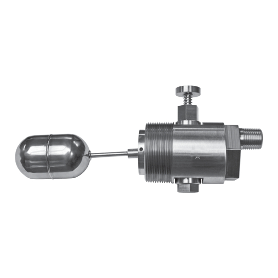
3.0 REFERENCE INFORMATION This section illustrates an overview of the L072 Side-Mounted Liquid Level Switch for Industrial Use, as well as information on troubleshooting common problems, agency approval listings, and detailed physical, functional and performance specifications. 3.1 DESCRIPTION The L072 Side-Mounted Liquid Level Switch for Industrial Use is a float-actuated device designed to be horizontally mounted within a process vessel through threaded or flanged connections. -
Page 9: Unit Causes
EXTERNAL CONDITIONS AS DESCRIBED IN SECTION 3.3.1. THE UNIT STILL DOES NOT FUNCTION. If you are still in doubt about the condition or performance of your sensor, consult the factory for further instructions. L072 SIDE-MOUNTED LIQUID LEVEL FLOAT SWITCH WITH MANUAL RESET... -
Page 10: Agency Approvals
316/316L Stainless Steel with 18-8 Stainless Pivot Pin HOUSING MOUNTING: Provisions for (4) #10 Screws PROCESS CONNECTION: 1 ½” NPT, 2” NPT, or BSP Threads 2”, 2 ½”, 3” or 4” (#150 or #300 ANSI Flanges) L072 SIDE-MOUNTED LIQUID LEVEL FLOAT SWITCH WITH MANUAL RESET... -
Page 11: Enclosure Specifications
∕ ” 3 ½” 3 ¾” L072 WITH FLANGED CONNECTION & 4.04” SPST or SPDT Switch with Flying Leads ½” NPT 2” Hex ∕ ” FLANGED CONNECTION 3 ½” 3 ¾” L072 SIDE-MOUNTED LIQUID LEVEL FLOAT SWITCH WITH MANUAL RESET... -
Page 12: Model Configurator
2 ½” Flange 120 VAC DPDT & OZ #300 Gedney GUALB-75 Box 3” Flange #300 4” Flange #300 L 0 7 0 - 0 8 0 8 3 0 0 4 L072 SIDE-MOUNTED LIQUID LEVEL FLOAT SWITCH WITH MANUAL RESET... -
Page 13: Notes
3.7 NOTES L072 SIDE-MOUNTED LIQUID LEVEL FLOAT SWITCH WITH MANUAL RESET... - Page 14 Products returned under RMAs can be issued through local representatives, or by the SWI Service Policy must be returned by prepaid contacting the factory directly. transportation. Solutions With Innovation will repair or...
Need help?
Do you have a question about the L072 and is the answer not in the manual?
Questions and answers