Advertisement
Table of Contents
- 1 Table of Contents
- 1 Chapter 1: Getting to Know Your AVL Electrolyte Analyzer
- 2 Chapter 2: Installation
- 3 Chapter 3: Programming
- 4 Chapter 4: Quality Control
- 5 Chapter 5: Operation
- 6 Chapter 6: Maintenance
- 7 Chapter 7: Troubleshooting and Service Functions
- 8 Chapter 8: Principles of Operation
- 9 Appendix A: Technical Specifications
- 10 Appendix B: Program Flow Chart
- Download this manual
Advertisement
Table of Contents

Related Manuals for AVL 9180


Summary of Contents for AVL 9180
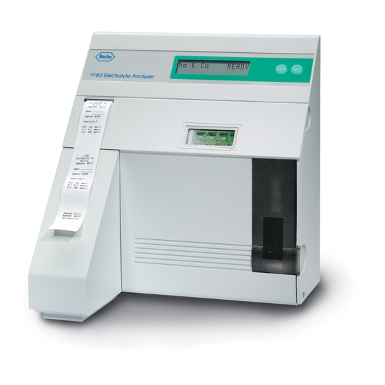
- Page 1 9180 Electrolyte Analyzer Operator's Manual...
- Page 2 2nd Edition June 1996 Copyright, 1996, AVL Scientific Corporation. All rights reserved. Unless otherwise noted, no part of this publication may be reproduced, transmitted, transcribed, stored in a retrieval system, or translated into any language in any form without the written permission of AVL Scientific Corporation.
- Page 3 The instrument is only to be operated by qualified personnel capable of observing these prerequisites. Only accessories and supplies either delivered by or approved by AVL are to be used with the instrument. Due to this instrument operating principle, analytical accuracy not only depends on correct operation and function, but also upon a variety of external influences beyond the manufactur- ers control.
- Page 4 Operating Safety Information This instrument falls under Safety Category I. • This instrument is a Class B instrument. • This device complies with Part 15 of the FCC Rules. Operation is subject to the following two conditions: (1) this device may not cause harmful interference’s, and (2) this device must accept any interference received, including interference that may cause undesired operation.
- Page 5 METHOD SHEET Intended Use The AVL 9180 Electrolyte Analyzer is intended to be used for the measurement of sodium, potas- sium, chloride, ionized calcium and lithium in samples of whole blood, serum, plasma, urine, dialy- sate and aqueous standard solutions.
- Page 6 The AVL 9180 Analyzer measures the ionized portion of the total calcium. In certain disorders such as pancreatitis and...
- Page 7 Elevated calcium, hypercalcemia, may be present in various types of malignancy, and calcium measurements may serve as biochemical markers. In general, while ionized calcium may be slightly more sensitive, either ionized or total calcium measurements have about equal utility in the detection of occult malignancy.
- Page 8 The AVL 9180 Analyzer methodology is based on the ion-selective electrode (ISE) measurement principle to precisely determine the measurement values. There are six different electrodes used in the AVL 9180 Electrolyte Analyzer: sodium, potassium, chloride, ionized calcium, lithium and a reference electrode. Each electrode has an ion-selective membrane that undergoes a specific reaction with the corresponding ions contained in the sample being analyzed.
- Page 9 The AVL 9180 Electrolyte Analyzer will accept samples directly from syringes, collection tubes, samples cups and, with the use of an adapter, from capillary tubes or the AVL Microsampler. For whole blood and plasma samples, a balanced heparin that does not affect the electrolyte values is the recommended anticoagulant of choice.
- Page 10 Whole Blood Whole blood samples should be collected in a heparinized syringe, AVL Microsampler or capillary and analyzed as soon as possible after collection. The sample container should be filled as much as possible, leaving minimal residual air space. If brief storage is required, do not cool the sample, as the erythrocytes could burst and release the intracellular potassium, creating an inaccurate potassium value in the sample.
- Page 11 Reagents ISE SnapPak (BP5186) containing the following reagents: Standard A Use: For calibration of sodium, potassium, chloride, ionized calcium and lithium in the AVL 9180 Electrolyte Analyzer Contents: 350 mL Active Ingredients: mmol/L mmol/L mmol/L mmol/L mmol/L Additives: Germicides Storage: Temperature: 5 - 30 °C (41 - 86 °F)
- Page 12 Temperature: 5 - 30 °C (41 - 86 °F) Stability: Expiration Date & Lot Number are printed on each container label. Reference Solution Use: A salt bridge for calibration and measurement in the AVL 9180 Electrolyte Analyzer Contents: 85 mL Active Ingredients: Potassium chloride 1.2 mol/L...
- Page 13 Expiration Date & Lot Number are printed on each container label. Urine Diluent (BP0344) Use: For use as a diluent for the measurement of urine samples in AVL electro- lyte system. Contents: Each bottle contains 500 mL of solution Active Ingredients:...
- Page 14 The AVL 9180 Analyzer allows the operator to select one of the following measuring modes: whole blood, serum, urine, standard, Q.C. material, acetate or bicarbonate depending on the sample type to be analyzed. The analyzer automatically processes the sample through the necessary steps, then prints and displays the results.
- Page 15 An automatic calibration procedure is also performed shortly after power-on or reset. A calibration cycle can also be initiated manually at times when no sample measurements are performed. Quality Control AVL recommends that at least once daily or in accordance with local regulations, quality control solutions with known Na , Cl...
- Page 16 The lithium electrode response is dependent on the actual sodium concentration of the sample. The AVL 9180 Analyzer reports lithium in the range of 105 - 180 mmol/L Na Interferences Salicylate, in extremely high levels, is known to interfere with the chloride electrode and results in a positive bias of the chloride result.
- Page 17 ) Precision is determined from 2 runs per day with 2 replicates per run for 20 days on two AVL 9180 analyzers in each of its three configura- tions. Values for sodium and potassium are average of all six instruments, while values for chloride, ionized calcium and lithium are determined from the measurement of two of each respective unit configuration.
- Page 18 Material: ISE-trol Protein Based Aqueous Control Material - Level 3 Parameter mean (CV%) (CV%) (CV%) Sodium 158.8 0.51 0.32% 0.76 0.48% 0.90 0.56% Potassium 5.74 0.027 0.48% 0.026 0.45% 0.036 0.62% Chloride 123.2 0.36 0.29% 0.89 0.72% 1.17 0.95% ionized Calcium 0.63 0.010 1.52% 0.007 1.07%...
- Page 19 Material: Pooled Human Serum Parameter mean (CV%) (CV%) (CV%) Sodium 138.8 0.30 0.22% 0.36 0.28% 0.47 0.34% Potassium 4.49 0.034 0.75% 0.041 0.92% 0.051 1.13% Chloride 106.8 0.18 0.17% 1.00 0.93% 1.24 1.16% ionized Calcium 1.19 0.007 0.55% 0.031 2.64% 0.039 3.29% Lithium 0.17...
- Page 20 Linearity in Aqueous Standard Solutions Aqueous linearity standards were gravimetrically prepared from N.I.S.T. traceable salts and mea- sured on each of six AVL 9180 instruments, two of each configuration: Na/K/Cl, Na/K/iCa and Na/ K/Li. Correlation Parameter Slope Intercept Coefficient Sy*x...
- Page 21 K = 4.0 0.11 Lithium 0.9803 0.011 0.9822 0.028 0.11-0.71 0.9720 0.016 0.9957 0.019 0.23-1.13 Correlation to Direct ISE - not flame correlated AVL 98X Electrolyte Analyzers Correlation Parameter Slope Intercept Coefficient Sy*x Range Sodium 0.9895 -6.35 0.9992 0.61 110-186 normalized to Na = 140 -7.83...
- Page 22 Correlation to Direct ISE - flame correlated AVL 91XX Electrolyte Analyzers Correlation Parameter Slope Intercept Coefficient Sy*x Range Sodium 0.9856 -2.02 0.9856 1.21 104-179 normalized to Na = 140 0.006 Potassium 0.9992 0.02 0.9994 0.05 1.9-11.8 normalized to K = 4.0 0.02...
- Page 23 Bibliography Bishop ML, Duben-Engelkirk JL, Fody EP. Clinical Chemistry Principles Procedures Correlations, 2nd Ed., (Philadelphia: J.B.Lippincott Co.),1992,p.281. Burritt MF, Pierides AM, Offord KP: Comparative studies of total and ionized serum calcium values in normal subjects and in patients with renal disorders. Mayo Clinic Proc. 55:606, 1980. Burtis C, Ashwood E (Eds.), Tietz Textbook of Clinical Chemistry, 2nd Ed., (Philadelphia: W.B.
- Page 24 xxiv...
- Page 25 Preface Welcome Your AVL Electrolyte Analyzer is a powerful tool designed to help you quickly, accurately and effi- ciently conduct basic electrolyte testing in the conve- nience of your own laboratory. This manual will help guide you through setting up your analyzer and will help you start analyzing samples.
- Page 26 xxvi...
-
Page 27: Table Of Contents
Contents Chapter 1: Getting to Know Your AVL Electrolyte Analyzer ............1 Chapter 2: Installation ..............11 Chapter 3: Programming ..............25 Chapter 4: Quality Control ............... 41 Chapter 5: Operation ............... 47 Chapter 6: Maintenance ..............55 Chapter 7: Troubleshooting and Service Functions ...... - Page 28 xxviii...
-
Page 31: Chapter 1: Getting To Know Your Avl Electrolyte Analyzer
Chapter 1 Getting to Know Your AVL Electrolyte Analyzer Important safety instructions Before you begin installing your AVL Electrolyte Ana- lyzer, carefully read the overview information in this chapter. For your own safety and the proper operation of your equipment, always follow these precautions when working with your AVL Electrolyte Analyzer: •... - Page 32 Control Panel Keypad Control Panel Display Front Door Sample Probe Mechanism ISE SnapPak 1-1. 9180 Electrolyte Analyzer Major Components (external)
- Page 33 Analyzer components The AVL Electrolyte Analyzer is a fully automatic, microprocessor-controlled medical instrument that measures: : Sodium : Potassium plus one of the following: : Chloride ¯ : Calcium : Lithium The analyzer consists of several major components that are important for you to know and understand while becoming familiar with the unit.
- Page 34 Measuring Chamber Thermal Printer Peristaltic Pump Sample Probe Mechanism Fluid Control Valves 1-4. 9180 Electrolyte Analyzer Major Components (internal)
- Page 35 Inside the unit are other components which are accessible by opening the main door. See illustration 1-4 and 1-5. 1-5. Opening the main door The measuring chamber consists of the movable left locking device that holds the electrodes in place, the electrodes, the right electrode holder with sample sensor connector, and the measuring chamber base.
- Page 36 Valves control the movement of the liquid within the analyzer. See illustration 1-8. 1-8. Fluid control valves The sample probe mechanism is located behind the small door at the front of the unit. See illustration 1-9. 1-9. Sample probe mechanism The self-contained ISE SnapPak uses an integral check-valve to ensure that waste cannot spill out of...
- Page 37 The thermal printer uses heat-sensitive paper to output information in 16 columns. The analyzer will print measured values, calibration values, electrode voltages, and amount of liquid remaining in the ISE SnapPak as well as cleaning and maintenance information. The unit is configured to allow conve- nient storage of a second roll of paper in the paper tray.
-
Page 41: Chapter 2: Installation
Chapter 2 Installation Choosing a location for the AVL Electrolyte Analyzer Location is important for trouble-free operation of your analyzer. Before you begin setup, choose a site that is convenient for your sampling needs and meets the following physical requirements of the unit: •... - Page 42 Now it’s time to unpack your AVL Electrolyte Ana- lyzer. Carefully remove the unit from the box. DO NOT lift the analyzer by the foam packaging materi- als, which are provided for shipping only. Before you begin installing your system, take a mo-...
- Page 43 Begin by placing the analyzer on a secure table top that allows plenty of working space and is convenient to a power connection. Open the analyzer main door. Locate and carefully remove the five red relief clamps from the valves by sliding out the clamps.
- Page 44 Unscrew the red transport housing from the reference electrode and check that the o-ring on the electrode is properly seated. Save the transport housing for storage of the reference electrode in the event the analyzer is turned off or taken out of service for any reason.
- Page 45 Locate the sample sensor cable and ensure that it is securely inserted into the receptacle above the measur- ing chamber. Check that an o-ring is present in the right electrode holder. See illustration 2-9. Now install the electrodes in the measuring chamber, beginning on the right and working to the left (the 2-9.
- Page 46 Slide the measuring chamber back until it snaps into position. See illustration 2-12. Plug the tubing connector of the reference housing assembly into the receptacle below the left side of the measuring chamber. See illustration 2-13. Preparing the analyzer for operation 2-12.
- Page 47 Push the power switch to the ON (I) position. The unit will automatically begin to operate. See illustration 2-15. Now that the AVL Electrolyte Analyzer is function- ing, you will begin using the keypad interface to communicate with the instrument. Use the NO key to make changes, the YES key to accept the displayed values or information.
- Page 48 5. After entering the time, the analyzer will prompt: OK? Press YES, if the date and time you entered is correct, or press NO to make a change. 6. After entering YES, the following prompt appears in the display : STATUS: NO SnapPak. Install the ISE SnapPak .
- Page 49 See illustration 2-19. Note: By pressing and releasing the paper advance button, the paper will automatically advance 10 lines. Your AVL Electrolyte Analyzer is now prepared for initial daily maintenance. 2-19. Paper advance button Initial daily maintenance...
- Page 50 The prompt Open Sample Door Introduce Sample will be displayed. Pour a small amount of AVL Cleaning Solution A into a clean sampling container. Lift the sample door. The prompt Introduce Sample will be displayed and the pump will begin to aspirate.
- Page 51 The prompt Open Sample Door Introduce Sample will be displayed. Lift the sample door. The prompt Introduce Sample will be displayed and the pump will begin to aspirate. Now, introduce the conditioning solution to the probe. See illustration 2-22. Hold the solution under the probe until the prompt Wipe Probe Close Sample Door is displayed.
- Page 52 YES to accept your selection. Note: If ([ Na ]) [ ] [ Li ] is selected, only lithium is reported. Install the Na electrode and calibrate for lithium. Congratulations! Your AVL Electrolyte Analyzer is ready for operation.
-
Page 55: Chapter 3: Programming
Chapter 3 Programming Your AVL Electrolyte Analyzer comes preset to easily and accurately perform sampling operations. Through the programming menu, you have the capa- bility to input additional information or parameters to tailor the instrument’s performance to match the particular needs of your lab. - Page 56 Code prompt. To exit this menu, press NO. Programming QC Level ranges When you open a new box of AVL ISE-trol Electro- lyte Controls, the lot number should be entered into the analyzer, along with the target ranges. Each level has its own lot number, which is printed on the infor- mational sheet contained inside the ISE-trol box.
- Page 57 Current Lot: 0000 Change Lot#? Note: The first time QC lot number information is entered, the AVL Electrolyte Analyzer will display a default lot number. Thereafter, the current lot num- ber will appear. Note: If you do not desire to change current lot information, but wish to verify current programmed QC ranges, press NO.
- Page 58 Additional Param- eters?. Pressing YES will allow you to program the deactivated parameters as well. After each range has been displayed, QC Level 1 pro- gramming will be completed. The AVL Electrolyte Analyzer will prompt Program QC Level 2 Ranges?
- Page 59 At the completion of QC Level 3 programming, the analyzer will prompt Program Normal Ranges? This programming feature allows you to customize the normal ranges that the AVL Electrolyte Analyzer will use to flag abnormal patient measurement values on both the display and printed report.
- Page 60 Press NO until Program Normal Ranges? is displayed. Press YES and the current Na low and high values will be displayed as such: Na low = 136 Na high = 145 ok? If the standard Na ranges are acceptable for your lab, press YES.
- Page 61 You may now adjust the high and low values by using the NO key to change the number, the YES key to accept the number. The analyzer will now display the current Ca activated) low and high values as such: Ca low = 1.12 Ca high = 1.32 ok?
- Page 62 Programming correlation factors Correlation factors allow you to correlate results from your AVL Electrolyte Analyzer to other electrolyte analyzers. Activated correlation values are taken into consideration when sampling whole blood, serum, plasma and QC samples. They are not used for standard samples analyzed in the QC/STD/DIALYSATE/URINE SAMPLE mode.
- Page 63 Pressing YES to the prompt Input / Verify Corr Factors? will allow you to input your own correla- tion factors or to verify or change correlation factors already programmed. The current values will be displayed, such as: Na(b) = +00.0 Na(m) = 1.000 ok? If the Na intercept (b) and the slope (m) are correct,...
- Page 64 This may be done using one of the following two methods: a) Correlation Factor Worksheet. 1. Measure the AVL ISE-trol level 1 and level 3, three times each on the AVL Electrolyte Analyzer and the reference analyzer. The three measured values for y = mx +b each device should not differ by more than 2.0 mml/L...
- Page 65 Note: If you select YES, you will advance to the Automatic Cal Report? prompt. If you select NO, the analyzer will display Print two Patient Reports?. Press YES if you want the AVL Electrolyte Analyzer to automatically produce two reports, NO to decline.
- Page 66 Program Interface? will be displayed. Press YES and the prompt Activate Data link? appears. Press YES if you wish to interface the AVL 9180 with an AVL Compact 2 blood gas analyzer. The data link with the AVL Compact 2 blood gas analyzer allows you to combine ISE results with pH/blood gas results on one printout.
- Page 67 For connection of the 9180 analyzer to the Compact 2 analyzer, the optional Interface Kit (BP5202) is required. To install the kit, first turn both instruments off. Connect the interface filter provided in the kit to the RS232 port on the 9180. Then connect one end of the cable to the interface filter, the other end to the COM 2 port on the Compact 2.
-
Page 71: Chapter 4: Quality Control
Chapter 4 Quality Control Running a QC sample To monitor the performance of your AVL Electrolyte Analyzer, you should run daily quality control samples using AVL ISE-trol Electrolyte Control (HC0033). These protein-based ISE controls allow you to moni- tor the analysis of sodium, potassium, chloride,... - Page 72 Press YES. The prompt Open Sample Door Introduce Sample will be displayed. Remove a Level 1 ampule from the box of ISE-trol and mix carefully. Gently tap the head of the ampule with your fingernail to remove any liquid. Carefully open the ampule by breaking off the top. Note: Protect your fingers by using gloves or tissue while breaking ampule.
- Page 73 ¯ Cl 125.1 3.05 77.8 Note: The AVL Electrolyte Analyzer “flags” values that are above or below the programmed target ranges by using an “up” or “down” arrow. The analyzer will automatically prompt Store Val- ues in Memory? To save the values in memory, press YES.
- Page 74 For the statistics, all values available for each parameter are used. After printing, the AVL Electrolyte Analyzer will return to READY. Note: If correlation factors are changed or QC values switched to direct ISE, ALL values in memory are...
-
Page 77: Chapter 5: Operation
Chapter 5 Operation The AVL Electrolyte Analyzer provides fast, conve- nient analysis of whole blood, serum, plasma, aqueous solutions, dialysate solutions and urine for: Sodium Potassium Chloride Calcium Lithium and Li are not measured in urine samples) The analyzer will accept specimens directly from most common containers, including collection tubes, sy- ringes, sample cups and capillary tubes. - Page 78 Whole blood samples should be analyzed as soon as possible within one hour after collecting the sample. If a brief storage is required, do not cool the sample as the erythrocytes could burst and release the intracellu- lar potassium, creating an inaccurate value of potassium in the sample.
- Page 79 Prior to measurement, always bring the sample to room temperature. Note: If lithium is activated, the dialysate mode is not available. Running a sample with the AVL Electrolyte Analyzer The AVL Electrolyte Analyzer provides fast, easy operation. Whenever READY appears on the dis- play, the unit is prepared to conduct sampling measurements.
- Page 80 Upon completion of analysis, the test results will be displayed and printed. 5-2. Cleaning probe See illustration 5-3. AVL 9180 ELECTROLYTE ISE NA - K - LI Note: Values that are higher or lower than the 01MAR96...
- Page 81 If an additional sample report is desired or the auto- matic sample report is turned off, the results may be printed by following these steps: 1. Press NO. 2. The prompt PRINT FUNCTIONS? will be displayed. 3. Press YES to accept. 4.
- Page 82 NA - K - CL 25MAR96 16:55 with AVL Urine Diluent (BP0344) in the ratio of 1 part urine to 2 parts diluent (e.g., 1 mL urine and 2 Name: ....
-
Page 85: Chapter 6: Maintenance
Maintenance and Operator Functions Scheduled Maintenance: Performing daily maintenance Prior to running your first sample of the day, the AVL Electrolyte Analyzer needs to undergo a simple cleaning and conditioning procedure that helps ensure the unit will perform properly. This procedure is... - Page 86 Press YES to start the cleaning procedure. The prompt Open Sample Door Introduce Sample will appear. At this time, pour a small amount of AVL Cleaning Solution A into a clean container. 6-1. Introducing Cleaning Solution A Lift the sample door and the pump will begin to aspirate.
- Page 87 You! . Upon completion of the countdown, the prompt Remain in Daily Maintenance? will be displayed. Press NO, and the AVL Electrolyte Ana- lyzer will automatically initiate a calibration cycle. Note: It is very important that the main door is closed during calibration, since it provides shielding from sources of electromagnetic interference.
- Page 88 READY. The exterior surfaces should be wiped clean with a soft, damp cloth. Note: Never use strong or abrasive cleaners on the AVL Electrolyte Analyzer. Use a slightly damp cloth to avoid getting fluid inside the analyzer. Performing monthly maintenance...
- Page 89 Slide the measuring chamber forward until it locks in the front position. See illustration 6-5. Unclamp the left electrode holder by moving the clamp forward. See illustration 6-6. Remove the reference electrode assembly from the analyzer. Unscrew the reference electrode from the reference housing.
- Page 90 Carefully screw the reference electrode into the reference electrode housing and place the assembly into the left side of the measuring chamber. Note that the reference electrode has a lip on the bottom that rests on the flat edge of the measuring chamber. See illustration 6-7.
- Page 91 Slide the measuring chamber back until it snaps into position, and close the front cover of the analyzer. See illustration 6-10. At this time, you may perform daily maintenance by pressing YES. If daily maintenance is not needed, press NO until CALIBRATION? is displayed. Press YES and a complete calibration cycle will be per- formed.
- Page 92 Install the new pump winding plate and slip the new pump windings over the analyzer pump rollers, being careful not to cross the tubes. Press NO until CALIBRATION? is displayed. Press YES to initiate a calibration cycle. Unscheduled Maintenance: 6-13. Slide chamber forward Changing electrodes Slide the measuring chamber forward until it locks in the front position.
- Page 93 Remove the new electrode from its protective box and check for the presence of an o-ring in the left side of the electrode. See illustration 6-16. 6-16. Electrode o-ring Install electrode in its labeled position in the measur- ing chamber. Note that the electrode has a lip on the bottom that rests on the flat edge of the measuring chamber to aid in proper positioning.
- Page 94 Slide the measuring chamber back until it snaps into position. See illustration 6-19. After installing a new electrode, the AVL Electrolyte Analyzer needs to undergo Daily Maintenance, Cali- bration and QC Measurement to verify the performance of the electrode. 6-19. Slide measuring chamber back...
- Page 95 SnapPak is installed. Press NO if you reinstall 6-21. Installing ISE SnapPak the pack that was removed. 8. Press YES, and the AVL Electrolyte Analyzer will automatically reset the fluid pack counter to 100% and commence system calibration. Standby mode...
- Page 96 NO to start cali- bration. Setting date and time The date and time of the AVL Electrolyte Analyzer can be easily changed as necessary. To change the date and time, enter the OPERATOR FUNC- TIONS? menu and press NO until Set Time /...
- Page 97 1. Press YES to enter the time/date setting menu. 2. The current time/date is displayed with the ques- tion OK? Respond with NO, if you want to change the time/date. Press YES to exit. 3. Press NO until the correct day is displayed. Press YES.
- Page 98 Resetting the sample number Each time a sample is analyzed, the analyzer will automatically advance the sample counter. If for any reason you wish to reset the counter, you can do so by entering the OPERATOR FUNCTIONS? menu and press NO until Reset Sample Number? is displayed.
- Page 99 • Two containers, one filled with at least 100 mL of water, the other one empty. • Five solenoid relief clamps (supplied with analyzer and shutdown kit) • Two reference electrode transport housings (supplied with shutdown kit) • One shutdown plug (supplied with shutdown kit) •...
- Page 100 Now the second transport housing is screwed into the reference housing. Place the reference housing back into the electrode holder and move the lever backwards, making sure all electrodes are seated properly. The electrode holder remains in the forward position. Press YES.
- Page 101 Unscrew the transport housing from the reference housing. Empty the reference housing and place all electrodes in their protective boxes. Remove the line with the red mark from its container. Now the shut- down plug can be removed. Press YES. See illustration 6-26.
- Page 102 For putting the analyzer back into operation, see Chapter 2. Changing printer paper The thermal printer paper supplied by AVL contains an indicator strip to alert you when the paper roll should be changed. To change the roll: 1. Open the front cover of the analyzer.
-
Page 105: Chapter 7: Troubleshooting And Service Functions
AVL Electrolyte Analyzer to operation. This chapter includes two sections, troubleshooting and service functions. If your AVL Electrolyte Analyzer does not perform correctly after conducting the basic steps outlined in this chapter, you should contact AVL for technical assistance. - Page 106 Troubleshooting STATUS: NOT CALIBRATED This message will be displayed when calibration has been interrupted. Possible remedies: • Perform system calibration to return the instru- ment to the READY mode. STANDARD A NOT DETECTED As the analyzer aspirates a sample of Standard A, the solution is detected by the sample sensor, which must detect its presence without encountering any air bubbles.
- Page 107 STANDARD B NOT DETECTED Detection of Standard B aspiration is the same as for Standard A. If Standard A is aspirated properly, but Standard B is not detected, check Standard B tubing for crystallization. If no crystallization or leaks are found, replace the ISE SnapPak STANDARD C NOT DETECTED (Li activated)
- Page 108 CHECK REFERENCE HOUSING When the analyzer fails to detect a flow of Reference Solution into the measuring chamber, CHECK REF- ERENCE HOUSING will be displayed. This test is performed at the beginning of each calibration cycle. Possible remedies: • Check for proper filling of the reference housing. •...
- Page 109 Possible remedies: • First, repeat the sample to see if it is detected properly on a second trial. • Close the sample door within time allowed. • Check sample aspiration and look for the presence of clots in the sampling system. •...
- Page 110 A, V, L, and checks if they are received within a set time period. Possible remedies: • Check to see if pins 2 and 3 are jumped correctly. Make sure jumper does not touch ground. • Contact AVL for technical assistance.
- Page 111 PAPER JAM OR PRINTER DEFECT If the printer attempts to print to the paper and the paper jams in the feeder, PAPER JAM OR PRINTER DEFECT will be displayed briefly, then the sample results will appear on the display. Possible remedy : •...
- Page 112 NA NOT CAL’D K NOT CAL’D CL NOT CAL’D CA NOT CAL’D LI NOT CAL’D These messages will be displayed in the event a specific electrode does not pass calibration. There are several possible reasons for an electrode not to pass calibration.
- Page 113 • Ensure that the sample sensor is securely plugged in and perform a sample sensor test to ensure the sensor is operating correctly. If necessary, clean the sample sensor. • Replace reference electrode housing. In case the unit displays arrows up or arrows down instead of the sample results, the concentration of the sample is outside of the measurement range (see specifications).
- Page 114 ERR. If the unit displays ERR. instead of the sample results, no valid voltage reading could be obtained from the electrode. Possible remedies: • Check for proper sample preparation (see Chapter 5). • Check for proper connection of the electrodes. •...
- Page 115 *** LI CALCULATION NOT POSSIBLE The lithium result can only be calculated for a Na range of 95 - 180 mmol/L (89.6 - 169.5 mmol/L for blood/serum). If the Na value of the sample is outside of this range, *** will be displayed and printed instead of the Li value.
- Page 116 Service Functions To aid in testing and troubleshooting your AVL Electrolyte Analyzer, there are various built-in functions that you can access to evaluate the performance of the instrument. From the READY display, press NO until the prompt SERVICE FUNCTIONS? appears. Press YES.
- Page 117 Introduce the sample to the probe until the prompt Remove Sample and Wipe Probe is received. After closing the sample door, the voltages will automatically appear. Check for stable readings. Press NO to exit and after a short Please Wait message, the prompt Remain in Test Electrodes? will appear.
- Page 118 NO to exit or perform other service functions. Note: The pump speed is electronically controlled and does not require any adjustment. Testing the valves The AVL Electrolyte Analyzer has five valves that function automatically during the operation of the instrument. See illustration 7-1.
- Page 119 Test Valve A: YES/NO = ON/OFF will appear. When you press the YES button, you should see the valve move into the open position. Pressing NO will close the valve. Pressing NO again will move to the next successive valve. After testing all valves, close the front cover and press NO to exit or perform other service functions.
- Page 120 Service Codes The Enter Service Code? menu allows the pro- gramming of various functions into the unit. To enter a service code, go to the SERVICE FUNCTIONS? display, press NO until Enter Service Code? appears. Press YES. The instrument will display Enter Code. Enter the desired service code by pressing NO to each letter, until the correct letter is displayed, then press YES.
- Page 121 This service code will automatically print the voltage levels of the electrodes on sample- and calibration re- ports. This code should only be used by trained service techni- cians. To disable this code, either enter IFI or turn the power off and back on. This service code will print the last 20 error messages with the date and time of occurrence.
- Page 122 This code allows the input of a percentage for the ISE SnapPak counter. When this code is activated, the analyzer displays: SnapPak Counter: xxx% ok? If this percentage is not correct, press NO and enter the correct percentage between 0 and 100% using the NO and YES keys.
-
Page 125: Chapter 8: Principles Of Operation
Chapter 8 Principles of Operation The measurement principle Your AVL Electrolyte Analyzer is a sophisticated medical instrument that uses the Ion Selective Elec- trode (ISE) measurement principle to precisely deter- mine electrolyte values. Although the technology itself is quite complicated, understanding how the instrument performs sampling analysis is relatively simple. - Page 126 chain is closed through the sample on one side by the reference electrode, the reference electrolyte and the “open terminal.” The membrane, inner electrolyte and inner electrode close the other side. See illustration 8-1. The different ion concentrations between the inner electrolyte and the sample causes an electro-chemical potential to form on the membrane of the active electrode.
- Page 127 Physical principle An ion-selective electrode is connected with a refer- ence electrode to form a measuring system. When immersed in a solution that contains the relative ion, the Nernst equation applies: R · T 1. E = E’± ——— · In a n ·...
- Page 128 If the ion concentration of one measuring solution is known, the ion concentration of the sample can be determined on the basis of the difference of two measured potentials. 4. E = E’ + S · log (f · c sample i sample 5.
- Page 129 The ion concentration is calculated on the basis of the ion activity. The correlation is affected by the total number of ions in the solution. Because sodium in whole blood and serum is the predominant ion, the known value of the sodium concentration makes it possible to ascertain and adjust for total ion effect and strength.
- Page 130 Pin connector: silver, silver chloride (Ag / AgCl) Use and Care AVL Sodium Electrodes are manufactured for use in AVL 9180 Electrolyte Analyzers. Proper care should be used in handling and storage of the electrode. Never use strong or abrasive cleaners such as alcohol or amphyl on the electrode since these will attack the plastic housing.
- Page 131 Pin connector: silver, silver chloride (Ag / AgCl) Use and Care AVL Potassium Electrodes are manufactured for use in AVL 9180 Electro- lyte Analyzers. Proper care should be used in handling and storage of the electrode. Never use strong or abrasive cleaners such as alcohol or amphyl on the electrode since these will attack the plastic housing.
- Page 132 Pin connector: silver, silver chloride (Ag / AgCl) Use and Care AVL Chloride Electrodes are manufactured for use in AVL 9180 Electrolyte Analyzers. Proper care should be used in handling and storage of the electrode. Never use strong or abrasive cleaners such as alcohol or amphyl on the electrode since these will attack the plastic housing.
- Page 133 Pin connector: silver, silver chloride (Ag / AgCl) Use and Care AVL Calcium Electrodes are manufactured for use in AVL 9180 Electrolyte Analyzers. Proper care should be used in handling and storage of the electrode. Never use strong or abrasive cleaners such as alcohol or amphyl on the electrode since these will attack the plastic housing.
- Page 134 Pin connector: silver, silver chloride (Ag / AgCl) Use and Care AVL Lithium Electrodes are manufactured for use in AVL 9180 Electrolyte Analyzers. Proper care should be used in handling and storage of the electrode. Never use strong or abrasive cleaners such as alcohol or amphyl on the electrode since these will attack the plastic housing.
- Page 135 Reference Electrode. See illustration 8-8. Use and Care AVL Reference Electrode Housings are manufactured for use in AVL 9180 Electrolyte Analyzers. Proper care should be used in handling and storage of the electrode housing.
- Page 136 Use and Care AVL Reference Electrodes are manufactured for use in AVL 9180 Electrolyte Analyzers. Proper care should be used in handling and storage of the Reference Elec- trode. Never use strong or abrasive cleaners such as alcohol or amphyl on the electrode.
- Page 139 Chapter 9 Supplies Each AVL Electrolyte Analyzer is shipped with an initial supply of calibrating and operating solutions, ISE-trol Electrolyte Control, accessories, and mainte- nance supplies. Below is a listing of all necessary supplies and acces- sories which you may need to replace during the use of your analyzer.
- Page 140 Printer Paper Tray RE5016 Reference Solution Double Tubing SS5000 Solenoid Relief Clamp YA0111 Stylet for Cleaning Sample Probe YA0836 Operators Manual for 9180 - English PD5006 Operators Manual for 9180 - International PD5008 Service Manual for 9180 US0285 Shut Down Kit BP5014...
- Page 141 Installation and Instrument Warranty Report form enclosed. It is necessary for this docu- ment to be completed and returned to AVL to ensure proper warranty support should you require warranty assistance. The model and serial numbers can be found directly behind the front cover on the right hand side, above the sample probe mechanism.
-
Page 142: Appendix A: Technical Specifications
Appendix A Technical specifications Electrodes Sodium (Na ) Sensor ion selective, flow-through, glass capillary electrode Potassium (K )Sensor ion selective, flow-through, liquid membrane electrode Chloride (Cl ) Sensor ion selective, flow-through, liquid membrane electrode ¯ Calcium (Ca ) Sensor ion selective, flow-through, liquid membrane electrode Lithium (Li ) Sensor ion selective, flow-through, liquid membrane electrode... - Page 143 Operating Parameters Sample size 95 µL Sample type whole blood, serum, plasma, dialysate, urine Sample application syringe, sample cup, collection tube, capillary Analysis time (approx.) 50 sec. Sample rate 60 per hr. without printout 45 per hr. with printout Calibration fully automatic 1- and 2-point calibrations Data management quality control memory storage,...
-
Page 144: Appendix B: Program Flow Chart
Appendix B Program flow chart... - Page 145 AVL 9180 ELECTROLYTE ANALYZER MAINTENANCE SCHEDULE _____________ MONTH OF 1 2 3 4 5 6 7 8 9 10 11 12 13 14 15 16 17 18 19 20 21 22 23 24 25 26 27 28 29 30 31...
- Page 146 Appendix D Correlation factor worksheet master Note: You may use this page as a master for duplicating. Parameter: Low Level / reference device Low Level / AVL Meas. No. 1 Meas. No. 1 Meas. No. 2 Meas. No. 2 Meas. No. 3 Meas.
- Page 148 AVL 9180 Electrolyte Analyzer Operator's Manual Written by Gerri Priest, Barbara Smith and Bernie Heitz of AVL. Edited by Randy Byrd, Tom McNulty and Steve Wickiser. Designed, illustrated and produced by Rick Burns and Drew Meincke.
Need help?
Do you have a question about the 9180 and is the answer not in the manual?
Questions and answers