Advertisement
Quick Links
This document is printed on chlorine free (ECF) paper with soy ink.
NV
011635
20020420-125000
SVV-200
SERVICE MANUAL
CONTENTS
SPECIFICATIONS .............................................................................. 3
PANEL LAYOUT .................................................................................. 4
CIRCUIT BOARD LAYOUT ................................................................. 6
BLOCK DIAGRAM .............................................................................. 7
DISASSEMBLY PROCEDURE ........................................................... 8
IC BLOCK DIAGRAM ......................................................................... 11
CIRCUIT BOARDS ............................................................................ 11
INSPECTIONS .................................................................................. 13
POINTS TO CHECK WHEN NOISE HAS OCCURED ..................... 13
.......................................................................................................... 14
.......................................................................................................... 14
TUNING ............................................................................................ 15
OVERALL CIRCUIT DIAGRAM
PARTS LIST
HAMAMATSU, JAPAN
0.944K-068
Printed in Japan 2002.05
Advertisement

Related Manuals for Yamaha Silent Viola SVV-200


Summary of Contents for Yamaha Silent Viola SVV-200
- Page 1 SVV-200 SERVICE MANUAL CONTENTS SPECIFICATIONS ................3 PANEL LAYOUT .................. 4 CIRCUIT BOARD LAYOUT ..............6 BLOCK DIAGRAM ................7 DISASSEMBLY PROCEDURE ............8 IC BLOCK DIAGRAM ................. 11 CIRCUIT BOARDS ................11 INSPECTIONS .................. 13 POINTS TO CHECK WHEN NOISE HAS OCCURED ..... 13 ......................
- Page 2 IMPORTANT NOTICE This manual has been provided for the use of authorized Yamaha Retailers and their service personnel. It has been assumed that basic service procedures inherent to the industry, and more specifically Yamaha Products, are already known and under- stood by the users, and have therefore not been restated.
- Page 3 SVV-200 SPECIFICATIONS Neck ......... Hard Maple Body ......... Spruce Fingerboard/Tuning Pegs ..Ebony Bridge ........Hard Maple (Aubert) Frame ........Plywood Chin Rest/Tailpiece ....Ebony Adjuster ........1st string (Wittner) Strings ........Ball-end type (Dominant) Sensor ........Stereo Piezo pick-up (underneath the bridge) Connectors/Controls ....
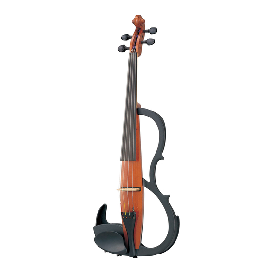
- Page 4 SVV-200 PANEL LAYOUT FRONT Tuning peg Neck Fingerboard 4th string (C) 2nd string (D) 3rd string (G) 1st string (A) Frame Body Bridge Chin rest Bridge seat Adjuster Tailpiece Tailpiece Wire End pin...
- Page 5 SVV-200 CONTROL PANEL side POWER Switch VOLUME EQ CTRL (Equalizer Control) EQ MODE Switch • EQ MODE 1 • EQ MODE 2 Adjustable Range Increase the Increase the low sensor high sensor Pickup Balancer (located inside) LINE OUT jack: Standard phone type PHONES jack: Stereo mini type Battery Case: 6F22(S-006P) 9V...
- Page 6 SVV-200 CIRCUIT BOARD LAYOUT PHONE Jack Battery Box...
- Page 8 SVV-200 DISASSEMBLY PROCEDURE PREPARATION Before disassemble the unit, proceed as follows. • Turn off the power. (Fig.1) • Remove the chin rest. • Remove the battery from the battery box. (Fig.2) • Remove all the strings and the bridge. (Fig.3) (Fig.
- Page 9 SVV-200 JK Circuit Board (Time required: about 2 min) Remove the three (3) screws marked [80] to remove the battery plate assembly. (Fig.4) Remove the hexagonal nut marked [A]. The JK circuit board can then be removed. (Fig.6) The JK circuit board is attached to the side board with adhesive tape, so remove it carefully.
- Page 10 SVV-200 Battery Box Assembly (Time required: about 2 min) Remove the battery plate assembly. (See procedure 2-1) Remove the four (4) screws marked [30]. The battery box assembly can then be removed. (Fig.4) Pickup Assembly (Time required: about 1 min) Remove the cover assembly.
- Page 11 SVV-200 IC BLOCK DIAGRAM NJM3414AM(T1) (XR294A00) LMH6647MAX (X3124A00) PC4570G2 (XF291A00) Dual Operational Amplifier Operational Amplifier Dual Operational Amplifier MA(Ver. A): IC5 MA(Ver. B): IC4 MA(Ver. A): IC1, IC2, IC3, IC4 MA(Ver. B): IC3 MA(Ver. B): IC5 +DC Voltage +DC Voltage Output A Output A N /C...
- Page 12 SVV-200 •MA Circuit Board POWER ON/OFF VOLUME EQ MODE (Ver. A) to JK-CN3 EQ CTRL Component Side Pickup Balancer Pattern Side •MA Circuit Board POWER ON/OFF VOLUME (Ver. B) EQ MODE to JK-CN3 EQ CTRL Component Side Pickup Balancer Pattern Side ENA-V883800 ENA-V883800 Note: See parts list for details of circuit board component parts.
- Page 13 SVV-200 INSPECTION Preparation To check the unit, following jigs are required. • Stereo Inner phones (Headphones) • Powered speaker • Battery (S-006P x 1) Load a battery into the product. Connect headphones and a powered speaker to [PHONE] jack and [LINE OUT] jack respectively. Perform each inspection aurally or visually.
- Page 14 SVV-200...
- Page 15 SVV-200 TUNING The Silent Viola is shipped from the factory with the bridge unfitted. First, set up the bridge and then proceed with tuning. • The lower side of the bridge supports the 1st string (A), the higher side supports the 4th string (C).
- Page 16 <P.1> SVV-200 SVV-200 OVERALL CIRCUIT DIAGRAM (MA -Ver. A-, JK) REGURATOR +5V RESET OP AMP OP AMP OP AMP Master Volume PICKUP PHONE BALANCER LINE OUT Battery 2SK1103-(TX) (VY891400) MA: FT1, FT2, FT3 OP AMP OP AMP KEC-54257 0 Pickup Volume CC11: Not installed (EQ CTRL) 1: SOURCE...
- Page 17 <P.2> SVV-200 SVV-200 OVERALL CIRCUIT DIAGRAM (MA -Ver. B-, JK) REGURATOR +5V RESET OP AMP OP AMP Master Volume PICKUP PHONE BALANCER LINE OUT OP AMP Battery KEC-54257 1 OP AMP Pickup Volume (EQ CTRL) NJU7202U50 (X0150A00) 2SA1162(O,Y) (VJ927200) 2SK1103-(TX) (VY891400) REGULATOR +5V 2SC2412K Q,R,S (VV556400) MA: IC8...
- Page 18 SVV-200 SVV-200 PARTS LIST CONTENTS OVERALL ASSEMBLY ...................... 2 ELECTRICAL PARTS ....................... 5 Note) DESTINATION ABBREVIATIONS Australian model South African model British model Chinese model Canadian model South-east Asia model German model Taiwan model European model U.S.A. model French model General export model (110V) North European model General export model (220V)
- Page 19 SVV-200 OVERALL ASSEMBLY A30b A30a C100 C110 D100...
- Page 20 SVV-200 DESCRIPTION REMARKS PART NO. QTY RANK REF NO. OVERALL ASSEMBLY SVV-200 Overall Assembly (V877070) Sub Assembly(2) (V877150) V8771600 Tailpiece Assembly String1,A Viola mittel #136 (V877170) String2,D Viola mittel #137 (V877180) String3,G Viola mittel #138 (V877190) String4,C Viola mittel #139 (V877200) Bridge (V877210)
- Page 21 SVV-200 DESCRIPTION REMARKS PART NO. QTY RANK REF NO. Saddle V-30 V-60 (V591290) End Pin (V877530) V8772900 Circuit Board (V883800) V8479300 Spacer V9365000 HP Jack Assembly VZ514300 Butyl-rubber Tape V9223100 Sheet D Body Assembly (V877470) Body (V877600) Neck (V877610) Flat Head Tapping Screw-1 3.0X14 MFZN2BL (VC04370) Finger Board...
- Page 22 SVV-200 ELECTRICAL PARTS DESCRIPTION REMARKS PART NO. QTY RANK REF NO. ELECTRICAL PARTS V8772900 Circuit Board (V883800) (X2529A0,X2529B0) V8773900 Circuit Board (V883800) (X2529A0,X2529B0) V8772900 Circuit Board (V883800) (X2529A0,X2529B0) V8773900 Circuit Board (V883800) (X2529A0,X2529B0) V8934700 LED Spacer VZ514300 Butyl-rubber Tape UE037100 CC001 Electrolytic Cap.
- Page 23 SVV-200 DESCRIPTION REMARKS PART NO. QTY RANK REF NO. RD357100 Carbon Resistor (chip) -0011 10K 63M J RF356680 R0012 Carbon Resistor (chip) 6.8K : D 1608 RF356680 Carbon Resistor (chip) R0013 6.8K : D 1608 RD357330 R0014 Carbon Resistor (chip) 33K 63M J RD357330 Carbon Resistor (chip)
Need help?
Do you have a question about the Silent Viola SVV-200 and is the answer not in the manual?
Questions and answers