Table of Contents
Advertisement
Quick Links
このサービスマニュアルはエコパルプ
(ECF:無塩素系漂白パルプ)を使用しています。
This document is printed on chlorine free (ECF) paper.
NV
011842
20061101-260400
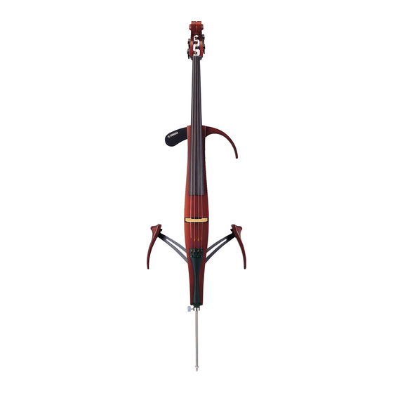
SVC210
SERVICE MANUAL
I CONTENTS (目次)
SPECIFICATIONS (総合仕様) ..................................................................... 3
PANEL LAYOUT (パネルレイアウト) ......................................................... 4
CIRCUIT BOARD LAYOUT (ユニットレイアウト).................................... 7
DISASSEMBLY PROCEDURES (分解手順) ............................................... 8
LSI PIN DESCRIPTION (LSI端子機能表) .................................................. 11
IC BLOCK DIAGRAM (ICブロック図) ...................................................... 11
CIRCUIT BOARDS (シート基板図) ........................................................... 12
(検査&雑音が出る場合のチェックポイント) ...................................... 14/16
TUNING (調弦) ......................................................................................... 18
BLOCK DIAGRAM (ブロックダイアグラム) ............................................ 19
OVERALL CIRCUIT DIAGRAM (総回路図) .............................................. 20
Copyright (c) Yamaha Corporation. All rights reserved.
HAMAMATSU, JAPAN
Printed in Japan '06.11
Advertisement
Table of Contents

Subscribe to Our Youtube Channel
Related Manuals for Yamaha SVC210


Summary of Contents for Yamaha SVC210
-
Page 1: Table Of Contents
TUNING (調弦) ..................18 BLOCK DIAGRAM (ブロックダイアグラム) ..........19 このサービスマニュアルはエコパルプ (ECF:無塩素系漂白パルプ)を使用しています。 OVERALL CIRCUIT DIAGRAM (総回路図) ..........20 This document is printed on chlorine free (ECF) paper. PARTS LIST 011842 20061101-260400 HAMAMATSU, JAPAN Copyright (c) Yamaha Corporation. All rights reserved. Printed in Japan ’06.11... - Page 2 IMPORTANT NOTICE This manual has been provided for the use of authorized Yamaha Retailers and their service personnel. It has been assumed that basic service procedures inherent to the industry, and more specifically Yamaha Products, are already known and understood by the users, and have therefore not been restated.
-
Page 3: Specifications (総合仕様
SVC210 SPECIFICATIONS (総合仕様) Neck 棹 (ネック) メイプル Maple Fingerboard 指板 エボニー (黒檀) Ebony 胴 Body Spruce / Maple スプルース/メイプル Knee Supports ひざ当て Beech ブナ Tuning Pegs 糸巻き ウォームギア方式 Worm Gear Type 駒 (ブリッジ) Bridge メイプル (Aubert) Maple (Aubert) テールピース Tail Piece Adjuster 4 pieces (Wittner) アジャスター4ピース付... -
Page 4: Panel Layout (パネルレイアウト
SVC210 PANEL LAYOUT (パネルレイアウト) • Front View (フロント部) Tuning peg (糸巻き「ペグ」) (上駒「ナット」) Neck 棹(ネック) Fingerboard (指板「フィンガーボード」) 2nd string (D) (第2弦「D」) 3rd string (G) (第3弦「G」) 1st string (A) (第1弦「A」) 4th string (C) (第4弦「C」) Arm rest Chest support (腕当て) (胸当て) Body (胴)... - Page 5 SVC210 • Rear View (リア部) Arm rest Chest support ( 腕当て ) (胸当て) Control panel (See Page 6) コントロールパネル部 (6ページ参照)...
- Page 6 SVC210 • Control Panel (コントロールパネル部) PHONES jack (Stereo headphones) (ステレオヘッドフォン端子) VOLUME (ボリューム) Lamp (ランプ) POWER switch REVERB switch REV.ON/ON/OFF RM/HL1/HL2 (POWER スイッチ) (REVERB スイッチ) DC-IN 9-12V jack (+ (電源アダプター接続) 端子 Cord hook (コードフック) Battery cover (電池ブタ) AUX VOL (AUX volume) (AUX ボリューム)...
-
Page 7: Circuit Board Layout (ユニットレイアウト
SVC210 CIRCUIT BOARD LAYOUT (ユニットレイアウト) • Rear View (背面パネル部)... -
Page 8: Disassembly Procedures (分解手順
SVC210 I DISASSEMBLY PROCEDURES (分解手順) 準備 Preparation Before disassembling, perform the following procedure. 分解を始める前に、以下の作業を行います。 • Remove the chest support and arm rest. (Fig. 1) ・ 胸当てと腕当てを外します。 (Fig. 1) • Hold the knee supports opened. (Fig. 2) ・ ひざ当てを開いた状態で固定します。 (Fig. 2) • Remove the battery from the battery case. - Page 9 SVC210 [S70] Control Panel Unit (コントロールパネルユニット) [CA110] (Fig. 5) [S70] [S70] [CA40] [CA40] [CA100] [CA50B] [CA50A] [S70] [CA50B] (Fig. 4) [S70]: Bind Head Tapping Screw #1 3x12 MFZN2B3 (WE985600) TP#1+BIND (Fig. 6) [CA50B]: Bind Head Screw 3x6 MFZN2B3 (WH380600) +バインド...
- Page 10 SVC210 HPシート (所要時間:約3分) HP Circuit Board (Time required: about 3 min.) コントロールパネルユニットを外します。 (1項参照) [B] の六角ナットを外し、HPシートを外します。 Remove the control panel unit. (See procedure 1.) (Fig. 4) Remove the hexagonal nut marked [B]. The HP circuit board can then be removed. (Fig. 4)
-
Page 11: Lsi Pin Description (Lsi端子機能表
SVC210 LSI PIN DESCRIPTION (LSI端子機能表) • YSS234 (XN299A00) Digital Sound Processor MA: IC1 NAME FUNCTION NAME FUNCTION AVDD DC A+5V DC D+5V External RAM interface data TST0 Test TST1 Test DOEN Test Master clock output... -
Page 12: Circuit Boards (シート基板図
SVC210 CIRCUIT BOARDS (シート基板図) • MA Circuit Board to HP-CN1 J2: Installed Installed to PICK UP SENSOR to JK-CN1 Component side (部品側) Pattern side (パターン側) MA : CNA-WH99820... - Page 13 SVC210 • HP Circuit Board to MA-CN3 PHONES • JK Circuit Board LINE OUT AUX IN to MA-CN2 Note: See parts list for details of circuit board component parts. 注 : シートの部品詳細はパーツリストをご参照ください。 HP : ENA-V286320 JK : ENA-V236320...
-
Page 14: Inspections & Mechanical Check Point (
SVC210 INSPECTIONS Preparations Unit Setting Unless otherwise specified, the controls and switches are to be set as follows. AUX VR : Maximum VOLUME : Maximum POWER switch : ON (REV OFF mode) REVERB switch : RM The [PHONES] and [LINE OUT] terminals are to be terminated with the following resistors. - Page 15 SVC210 • AUX IN inspection With turned on the power, input stereo signal to the terminals of AUX IN, then check the signal is output correctly at L and R terminals of LINE OUT. • POWER switch mode inspection Confirm that the power LED lights up according to the following table when selecting the POWER switch position.
- Page 16 SVC210 検査 準備 測定条件 特に指定のない限りボリューム、スイッチの設定、ジャックの接続は、下記の状態とします。 AUX VR :最大 VOLUME :最大 POWERスイッチ :ON (REV OFFモード) REVERBスイッチ :RM 出力端子は下記の状態とします。 PHONES :負荷抵抗 150Ω LINEOUT :負荷抵抗 10 kΩ 測定器、治工具 検査には、下記の測定器や治工具を使用します。 測定器 :低周波発振器、レベルメータ ※低周波発振器の出力は600Ωで終端します。 ※ノイズレベルは、特性FLATで測定します。 治具 :ACアダプタ (PA-3C) 、アンプ内臓スピーカ、AUX IN用ステレオ出力音源 (CDプレーヤーな ど) 、ヘッドホン 検査 [0 dBu=0.775 Vrms] 項目 規格値 信号入力および設定 出力レベル 1 PHONES (L)...
- Page 17 SVC210 ・ AUX IN 検査 電源ONの状態でAUX INにステレオ信号を入力し、LINE OUT のL, R各チャンネルから正しく出力されることを確認します。 ・ 電源モードの検査 POWERスイッチを切り換えて、LEDの点灯色を確認します。 REV.ON LED赤色に点灯 LED緑色に点灯 LED消灯 PHONES ( L、R) 及びLINE OUT (L、R) に出力される電源切り替え時のクリックノイズが、0.1 VP-P以下であることを確認 します。 また、ONからREV.ONへ切り替えた時に、デジタルノイズが出力されないことを聴覚で確認します。 出荷時の設定 POWER : OFF VOLUME : MIN REVERB : HL2 AUX VOLUME : MIN 雑音が出る場合のチェックポイント ビリツキなどメカニカルな雑音の発生時は下記の点のチェックと調整を行ってください。 1. アジャスターのネジ部が出すぎるとガタツキが生じて雑音の原因に なりますので、緩めすぎないようにしてください。 2. アジャスター取り付けネジの緩みをチェックし、しっかり締め付け てください。...
-
Page 18: Tuning (調弦
SVC210 TUNING (調弦) The Silent Electric Cello is shipped from the factory with the bridge unfitted. First, set up the bridge and then proceed with Slit 4th string 1st string tuning. (溝) (第4弦側) (第1弦側) 出荷時、駒はサイレントチェロ本体から外してあります。 まず駒を本体に正しく取り付けてから、調弦してください。 • The lower side of the bridge supports the 1st string (A), the Logo higher side supports the 4th string (C). -
Page 19: Block Diagram (ブロックダイアグラム
SVC210 BLOCK DIAGRAM (ブロックダイアグラム) +5DA 34,58 16(ICN) * PLATE 9-14 MODE REVERB 1.5S (ROOM*) 15 (MUTE) 1.5S (HALL) IC13 25,27 30 29 CN1-2P +5DA 2.0S (HALL) PICK UP SENSOR IC11a IC8b CN3-4P CN1-4P IC10a IC14 IC12a +5DA CN2-6P IC11b IC10b... -
Page 20: Overall Circuit Diagram (総回路図
SVC210 OVERALL CIRCUIT DIAGRAM (総回路図) X : not installed REVERB KEC-54309 SRAM BS62LV256SCP70 OP AMP OP AMP VOLUME SYSTEM RESET KEC-54309 to PICK UP SENSOR X : not installed OP AMP • 1SR154-400 (VT532500) DIODE • 1SS355 TE-17 (VT332900) DIODE •... -
Page 21: Parts List
SVC210 SVC210 PARTS LIST I CONTENTS (目次) OVERALL ASSEMBLY (総組立) ............2 CONTROL PANEL UNIT (コントロールパネルユニット) ..... 5 ELECTRICAL PARTS (電気部品) ............7 Notes: DESTINATION ABBREVIATIONS Australian model South African model British model Chinese model Canadian model South-east Asia model... - Page 22 SVC210 OVERALL ASSEMBLY (総組立) S130 Control Panel Unit (See Page 5) コントロールパネルユニット (5ページ参照) BA20 BA10 BA40 BA30 BA40 BB20 BB40 BA70 BB60 S130 BB30 BA80 BB50 BA90 BB10 S120 BA100 BA50 BA60 S100 S20a S110 N10a BA100 BB100 N10b BB90...
- Page 23 SVC210 PART NO. DESCRIPTION 部 品 名 REMARKS REF NO. RANK OVERALL ASSEMBLY 総 組 立 SVC210 Overall Assembly 総 組 立 (WH39260) Sub Assembly サ ブ A s s y (WH39270) WG668000 ナ ッ ト V 2 8 5 0 8 0 0 Saddle サ...
- Page 24 SVC210 PART NO. DESCRIPTION 部 品 名 REMARKS REF NO. RANK * A120 WG848000 Chest Support Assembly 胸 当 て A s s y * A130 WH393600 Arm Rest Assembly 腕 当 て A s s y OPTION 別 売...
- Page 25 SVC210 CONTROL PANEL UNIT (コントロールパネルユニット) Accessories of Phone Jack CA10 (ホーンジャック付属品) CB10 CB90 CA80 CA70 CA120 CA110 CA40 CA90 CB90 CA20 CA100 CB100 CB30 CB20 CA40 CB50 CB40 CA30 CB90 CB80 CB70 CB60 CA50 CB90 CA50 Accessories of Volume (ボリューム付属品)...
- Page 26 SVC210 PART NO. DESCRIPTION 部 品 名 REMARKS REF NO. RANK Control Panel Unit コ ン パ ネ ユ ニ ッ ト (WH99770) CA10 V 2 8 6 6 0 0 0 Control Panel Assembly コ ン パ ネ A s s...
- Page 27 SVC210 ELECTRICAL PARTS (電気部品) PART NO. DESCRIPTION 部 品 名 REMARKS REF NO. RANK ELECTRICAL PARTS 電 気 部 品 SVC210 V 2 8 6 3 5 0 0 Circuit Board J K シ ー ト (V286320)(XV406A0) V 2 8 6 3 6 0 0 Circuit Board H...
- Page 28 SVC210 PART NO. DESCRIPTION 部 品 名 REMARKS REF NO. RANK VR328600 Mylar Capacitor (chip) 470pF 50V J チ ッ プ マ イ ラ ー VR326000 Mylar Capacitor (chip) 6800pF 16V J チ ッ プ マ イ ラ ー US145100 Ceramic Capacitor-F (chip) 0.1uF 25V Z...
- Page 29 SVC210 PART NO. DESCRIPTION 部 品 名 REMARKS REF NO. RANK RD355680 Carbon Resistor (chip) 680 1/16W J チ ッ プ 抵 抗 RD358100 Carbon Resistor (chip) 100K 1/16W J チ ッ プ 抵 抗 RD358100 Carbon Resistor (chip) 100K 1/16W J チ...
- Page 30 SVC210 PART NO. DESCRIPTION 部 品 名 REMARKS REF NO. RANK VZ266300 Slide Switch SSSF043-S06N0 HV ス ラ イ ド S W POWER VY891800 Slide Switch SSSF023-S06N0 ス ラ イ ド S W REVERB V J 9 2 7 2 0 0 Transistor “2SA1162 O,Y”...
Need help?
Do you have a question about the SVC210 and is the answer not in the manual?
Questions and answers