
Related Manuals for Spearhead SP15


Summary of Contents for Spearhead SP15
- Page 1 8999169EN: v1.0 25/01/2022 Spearhead Machinery Operator Instruction Manual For 1.50m to 2.10 cut width Original instructions (ENGLISH) Website: www.spearheadmachinery.com...
- Page 2 Verification Of Warranty Registration Dealer Warranty Information & Registration Verification It is imperative that the selling dealer registers this machine with Spearhead before delivery to the end user. Failure to do so may affect the validity of the machine warranty.
- Page 3 8999169EN: v1.0 25/01/2022 (This page is left blank intentionally) Original instructions (ENGLISH) Website: www.spearheadmachinery.com...
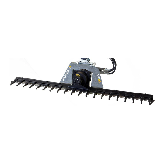
- Page 4 Machines are available in a choice of either 1.50m, 1.80m or 2.10m working widths; fitted with cutting knives. Designed for use on Spearhead’s reach arm range, the SP cutterbar is the ideal machine for landscaping, gardening, agriculture, forestry and other similar applications.
- Page 5 8999169EN: v1.0 25/01/2022 (This page is left blank intentionally) Original instructions (ENGLISH) Website: www.spearheadmachinery.com...
-
Page 6: Table Of Contents
8999169EN: v1.0 25/01/2022 Contents List Machine Description ..........................8 Intended Usage......................... 8 General Arrangement ....................... 9 Machine Identification ......................10 Machine General Specification....................11 1.4.1 Standard Specification....................11 Safety ..............................12 Safety Warnings ........................12 Terminology ..........................12 Unauthorized Conversions And Modifications Are Prohibited .......... - Page 7 8999169EN: v1.0 25/01/2022 4.8.1 Pre-start Checks ......................37 4.8.2 Starting The Cutterbar ....................39 4.8.3 Stopping The Cutterbar ..................... 39 4.8.4 Stopping The Machine In An Emergency ..............39 General Cutting Hints ......................39 4.9.2 Hedge Cutting Hints ....................40 4.10 Transporting The Cutterbar .....................
-
Page 8: Machine Description
Machines are available in a choice of either 1.50m, 1.80m or 2.10m working widths; fitted with cutting knives. Designed for use on Spearhead’s reach arm range, the SP cutterbar is the ideal machine for landscaping, gardening, agriculture, forestry and other similar applications. -
Page 9: General Arrangement
8999169EN: v1.0 25/01/2022 General Arrangement The layout and naming convention used throughout this manual are shown in Figure 1.2 below Item No Description Hydraulic Hose Connections Hydraulic Motor Reciprocating Motor Drive Machine Safety Guard Knife Knife Guard Safety Cutterbar Mount Bracket Knife Guard Warning Decal Serial Plate Mount Bracket Warning Decals... -
Page 10: Machine Identification
By utilising a smart phone and scanning the Authorised Representative QR scan code found on the right-hand side of the serial plate (ref 8, Figure 1.3) using a suitable QR scanning App, you can find details for Spearhead Machinery authorised representatives for its various territories. -
Page 11: Machine General Specification
3 mph (5 km/h) Table 1.1 Notes: (1) Spearhead constantly reviews and improves product designs and reserve the right to change this information. Actual machines may vary from the above specification. Contact your Spearhead Sales representative if you have any queries. -
Page 12: Safety
- GENUINE SPEARHEAD DEALER/ AUTHORIZED TRACTOR DEALER: The Genuine Spearhead Dealer/ Authorized Tractor Dealer, legally authorised by the Manufacturer, is formed by specialised staff able to carry out all types of assistance, maintenance and repair work, even of a certain complexity, required to maintain the machine in perfect working order. -
Page 13: Unauthorized Conversions And Modifications Are Prohibited
IMPORTANT: Only spare parts that are supplied by or have the explicit approval of the manufacturer must be used. The manufacturer accepts no liability and provides no guarantee in the event of damage or injury caused by the use of non-original/genuine Spearhead parts. Safety Information For Operation IMPORTANT: Familiarise yourself with all devices and operating components, as well as their function, before starting the work. - Page 14 8999169EN: v1.0 25/01/2022 IMPORTANT: Check all mechanical and hydraulic connections and all installed safety devices for their functionality before using the machine. CAUTION! Check that the hydraulic hoses are correctly positioned. Hydraulic hoses that get caught up or crushed may cause personal injury (e.g. as a result of seeping hydraulic oil) or damage to the machine.
-
Page 15: Safety Information For Assembly, Maintenance And Repair Work
8999169EN: v1.0 25/01/2022 DANGER! The hedge cutter may carry on running after it is switched off. Wait until it has stopped entirely. WARNING! During work breaks you should place the hedge cutter on the ground and install the Knife Guard and safety guards. DANGER! With hydraulically activated parts there is a risk of body parts becoming crushed and detached. -
Page 16: Dangers Due To Overhead Power Lines
There are significant dangers involved when working in the vicinity of Overhead Power Lines (OHPL’s). Be aware that some Spearhead machines are capable of reaches in excess of 8 metres (26’) and have the potential to well exceed; (by possibly 3 metres (9’ 9”); the lowest legal minimum height of 5.2 metres from the ground for 11,000 and 33,000 volt power lines, see Figure 2.1. - Page 17 8999169EN: v1.0 25/01/2022 Figure 2.1 - Minimum Heights For Overhead Power Lines Figure 2.2 - Absolute Minimum Exclusion Zones For Specific Overhead Power Lines Figure 2.3 - Definitions Of Exclusion Zones Original instructions (ENGLISH) Website: www.spearheadmachinery.com...
-
Page 18: Safety Decals
8999169EN: v1.0 25/01/2022 Safety Decals Machine safety decals are located in various points on the machine; see Figure 2.4. They can be identified in yellow with the upper panel depicting the hazard, and the lower panel indicating means of avoidance or precautions to be taken. -
Page 19: Placement
It is of upmost importance that safety decals are kept clean and replaced if they are no longer legible, damaged or lost completely. Safety decals can be purchased readily from a local Spearhead dealer. For more extensive guidance on ordering spare parts and how to go about finding the correct part number; see Section 7. -
Page 20: Guarding
Spearhead Machinery disclaim all responsibility for any damage or injury arising as a result of guards being removed, or of guards other than of Spearhead manufacture having been fitted, or of operation of the machine other than in accordance with these instructions. -
Page 21: Personal Protective Equipment
8999169EN: v1.0 25/01/2022 2.11 Personal Protective Equipment Operators should be wearing sufficient personal protection equipment (PPE) to protect them from hearing, respiratory and impact damages. When working in an unsealed cab or where windows and apertures are open to the environment, operators are advised to wear suitable eye and ear protection, a facemask (depending on conditions) and head protection. -
Page 22: Working On Inclined Ground
When working on top of embankments it is very important to have sufficient forward stability to ensure rapid steerage control. Spearhead recommend 20% forward stability. This means that at least 20% of the total vehicle weight is acting on the steering axle under normal level conditions. -
Page 23: Working In Public Places
8999169EN: v1.0 25/01/2022 2.16 Working In Public Places When working in public places such as roadsides, consideration should be paid to others in the vicinity. Stop the machine immediately when pedestrians, cyclists and horse riders etc. pass. Restart only when they are at a distance that causes no risk to their safety. -
Page 24: Warning Signs
8999169EN: v1.0 25/01/2022 2.18 Warning Signs It is advisable that any working area be covered by suitable warning signs in public places. Signs should be highly visible and well placed in order to give clear advanced warning of the hazard. Contact the Department of Transport or your Local Highways Authority to obtain detailed information on this subject. -
Page 25: The Machine & The Environment
In most instances Spearhead machines can be broken into its constituent parts with the use of basic workshop equipment. Table contains a typical list of constituent materials, together with disposal guidelines. -
Page 26: Proposition 65
8999169EN: v1.0 25/01/2022 2.20 Proposition 65 Figure 2.10 Operating, servicing and maintaining this equipment can expose you to chemicals including gasoline, diesel fuel, lubricants, petroleum products, engine exhaust, carbon monoxide, and phthalates, which are known to the State of California to cause cancer and birth defects or other reproductive harm. To minimize exposure, avoid breathing exhaust, do not idle the engine except as necessary, service your vehicle in a well-ventilated area and wear gloves and wash your hands frequently when servicing your vehicle. - Page 27 8999169EN: v1.0 25/01/2022 (This page is left blank intentionally) Original instructions (ENGLISH) Website: www.spearheadmachinery.com...
-
Page 28: Machine Preparation
Lifting Equipment Spearhead recommends that the cutterbar is stored on a substantial and suitable pallet in good condition when not in use. If it needs to be moved use a pallet lifter or forklift or sufficient capacity to cater for the weight of the cutterbar. -
Page 29: Post-Delivery/First Use Inspection
Spearhead machines are tested after manufacture. It is important to assess the machine to ensure that it is of the correct specification ordered from Spearhead or local Spearhead dealer. Information with regards to the specification of the machine can be found on the serial plate. -
Page 30: Usage Instruction
Section 2.9. The connecting tractor and reach arm will also have them as well with information given in the operator’s manual. If any part of the operation safe use of the machine is not completely understood, consult a local Spearhead dealer or Spearhead for complete explanation. -
Page 31: Controls Overview
Figure 4.3 The cutterbar can be mounted on Spearhead’s range of Twiga reach arms; Twiga Compact, Twiga Classic, Twiga Mid, Twiga Pro and Twiga Flex. In addition, it can also be mounted on Spearhead’s Twiga Carrier loader frame. Always bear in mind that the maximum oil flow that the cutterbar needs is also the flow that the loader frame or hydraulic reach arm is able to supply. -
Page 32: Machine Protection Guard
8999169EN: v1.0 25/01/2022 Depending on which reach arm/loader frame you wish to fit the cutterbar will determine how the cutterbar will be required to be fitted to the reach arm. Some models require an intermediate adaptor bracket to be fitted to the cutterbar to allow it to be successfully fitted to the reach arm and others have a simple, direct fitment. -
Page 33: Hydraulic Installation
8999169EN: v1.0 25/01/2022 The machine protection guard must be removed prior to start up with the motor switched off and the oil not under pressure, and replaced only once the machine has stopped completely – the guard should be in position at all times during transportation of the machine as a means of safeguarding people and machine. -
Page 34: Hydraulic Hose Checks
8999169EN: v1.0 25/01/2022 Disconnecting IMPORTANT: The machine should be secure at all times when left unattended so it doesn’t move. Ensure that the machine is stored off the ground, preferably in a dry location to preserve its condition; for example on a pallet. -
Page 35: Sharp Bends
As a general guideline, hoses should not be bent round a radius smaller than ten times the hose diameter. This will vary with hose construction and any queries about specific hoses should be addressed to the Spearhead Machinery service department. Figure 4.7 4.6.3... -
Page 36: Work Site Assessment
8999169EN: v1.0 25/01/2022 Work Site Assessment 4.7.1 Foreign Debris Hazards The destined work site to use the machine should be thoroughly checked and familiarised to assess the working area for hazards; removable and fixed. Items should be assessed, removed or clearly marked (e.g. if too heavy to move) before cutting: •... -
Page 37: Bystanders
8999169EN: v1.0 25/01/2022 4.7.2 Bystanders It is of upmost importance that the tractor and reach arm and attachments are stopped immediately if a bystander comes within 90m (300 ft) while operating. The engine should be idled and the PTO disengaged. Do not restart work until the bystander is well past the 90m (300 ft) and the work zone has been reassessed to ensure there are no external risks. - Page 38 Refer to the operator manuals for the tractor and reach arm. Spearhead SP cutterbars can be supplied with different motors depending on the carrying reach arm in which they’re meant to be fitted to. See Table 4.1 For guidance on the correct oil flow requirement for the specification of cutterbar supplied.
-
Page 39: Starting The Cutterbar
8999169EN: v1.0 25/01/2022 4.8.2 Starting The Cutterbar Once pre-start checks have been carried out, the machine is can then be started. Start the machine at low oil flow (low rpm). If the machine is starting from cold, warm the machine up for approximately 15 minutes to heat up the oil. -
Page 40: Hedge Cutting Hints
All Spearhead cutterbars are designed to be operated at an angle in relation to the direction of travel. This ensures an optimal cut, as the branches often bend slightly in the direction of travel, and the newly cut branches easily “slip past”... -
Page 41: Transporting The Cutterbar
Angle the attachment in order to take up the least amount of space. For Spearhead machines with slewing ability the reach arm should be slewed behind the tractor. Be mindful, if the reach arm is lifted to the transportation stop that it doesn’t hit the cab of the vehicle or will hit the cab during transportation. - Page 42 It is of upmost importance that safety decals are kept clean and replaced if they are no longer legible, damaged or lost completely. Safety decals can be purchased readily from a local Spearhead dealer. After work and all debris is swept away from footpaths and highways ensure that the work site is tidied.
- Page 43 8999169EN: v1.0 25/01/2022 (This page is left blank intentionally) Original instructions (ENGLISH) Website: www.spearheadmachinery.com...
-
Page 44: Maintenance
Inspect for loose or missing fasteners, worn or broken parts, leaky or loose fittings, worn bushes and any other moving parts which are worn or missing. Replace any worn or broken parts with genuine Spearhead parts under the guidance of the specific section stated in Section 5. -
Page 45: Knives & Drive System
Distortion • Cracks For safety and performance only use genuine Spearhead knives. When replacing knives it is important that new knife bolts are fitted. Knife wear blocks should be inspected for wear and replaced if excessively worn. Inspect the knives before each use to determine that they are properly installed, secure and in good condition. A knife that is bent, excessively nicked, worn or have any other damage should be replaced. - Page 46 8999169EN: v1.0 25/01/2022 Loosen the nuts on the damaged knife and tap the serrated stud bolts to remove them. Remove the knife from the knife mount bar. Figure 5.2 Replacement As the cutterbar’s fingers are supplied with a double cutting edge (on the topside and the underside), the knife teeth can be turned in both directions.
-
Page 47: Replacing A Complete Knife Set
8999169EN: v1.0 25/01/2022 Slide the double knife guard back over the the new knife. Insert the bolts. Tighten the nuts to the specified tightening torque. – 48 Nm (35 ftlb) Figure 5.5 5.4.3 Replacing A Complete Knife Set If the multiple knives are excessively worn, the entire knife set must be replaced. Removing The Knife Set From The Cutterbar Assembly Align the motor so that the bolts on the motor drive bearing are pointing upwards. -
Page 48: Replacing Multiple Knives On The Mount Bar
8999169EN: v1.0 25/01/2022 Remove the three loose knives toward the rear between the two guards. Figure 5.8 Pull the knife mount bar carefully through to remove it from the cutterbar assembly. Figure 5.9 5.4.4 Replacing Multiple Knives On The Mount Bar Loosen and remove the nuts on the three knives which need to be replaced. - Page 49 8999169EN: v1.0 25/01/2022 Loosen the two outer bolts on the knife mount bar. Remove the knife mount bar. Figure 5.11 Mount the new knife mount bar on the knife assembly. Make sure that the protrusions of the press- in nuts point upward and are seated properly during assembly.
- Page 50 8999169EN: v1.0 25/01/2022 Insert the three loose knives from the rear between the two knife motor guards in front of the knife head and push them into the mounting position. Figure 5.14 Place the knife head on the knives. Tighten the bolts to the specified tightening torque.
-
Page 51: Replacing A Double Knife Guard
8999169EN: v1.0 25/01/2022 Check the cutting gap for parallelism. Observe the section while it runs very slowly. If the knife scrapes or does not run straight in the cutting gap, the cause must be determined and eliminated. Figure 5.17 5.4.5 Replacing A Double Knife Guard A guard must be replaced if it is bent or damaged, or if the cutting gap has reached the wear mark of 5.4 mm. - Page 52 8999169EN: v1.0 25/01/2022 Push the double knife guard through the resulting gap left by the removed knife. Figure 5.20 Replacement Push the new double knife guard through the gap left by the removed knife. Push the double guard aside to allow the knife to be replaced in position.
-
Page 53: Replacing A Knife Arm Guard
8999169EN: v1.0 25/01/2022 Slide the double knife guard back over the knife. Insert the bolts. Tighten the nuts to the specified tightening torque. – 48 Nm (35 ftlb) Figure 5.23 5.4.6 Replacing A Knife Arm Guard Removal Of A Knife Arm Guard Unscrew the nuts on the knife arm guard and remove the bolts. -
Page 54: Replacing The Safety End Finger
8999169EN: v1.0 25/01/2022 5.4.7 Replacing The Safety End Finger If the position of the safety end finger on the guard is not correct, it can be aligned to correct this. Damaged safety end fingers must be replaced immediately. Removal Unscrew the nuts holding the safety end finger and remove the bolts. -
Page 55: Replacing The Wear Plate
8999169EN: v1.0 25/01/2022 5.4.8 Replacing The Wear Plate If the wear plates are worn, they must be replaced. Loosen and remove the fasteners holding the wear plate. Figure 5.28 Push the worn wear plate out to the rear over the mount bar. Figure 5.29 Replacement Push the new wear plate from the rear... -
Page 56: Replacing The Knife Head
8999169EN: v1.0 25/01/2022 Position the two knife guards correctly on the wear plate. Insert the bolts. Tighten the nuts to the specified tightening torque. – 48 Nm (35 ftlb) Figure 5.31 5.4.9 Replacing The Knife Head If the knife head is bent, damaged or deformed, it must be replaced immediately. Removal Align the motor so that the bolts on the motor drive bearing are pointing upwards. - Page 57 8999169EN: v1.0 25/01/2022 Removing The Head Bearing Loosen the bolt on the knife head. Remove the head bearing from the knife head. You can spread the knife head somewhat by inserting a small screwdriver into the slot of the knife head. Figure 5.34 Replacing The Head Bearing Insert the head bearing in the new knife...
- Page 58 8999169EN: v1.0 25/01/2022 Tighten the bolts on the head bearing to the specified tightening torque. – 81 Nm (60 ftlb) Figure 5.37 Tighten the bolts on the knife head to the specified tightening torque. – 72 Nm (53 ftlb) Figure 5.38 Check the cutting gap for parallelism.
-
Page 59: Hydraulic Components
8999169EN: v1.0 25/01/2022 Hydraulic Components Before proceeding to carry out any maintenance requirements on the hydraulic system, ensure that you have thoroughly read and understood Section 2.7 on how to safely go about carrying out maintenance requirements to the cutterbar, including how to approach the hydraulic system and its components. Section 2.6 should also be read to understand how to safely operate and use the machine in general. -
Page 60: Lubrication & Greasing
8999169EN: v1.0 25/01/2022 Lubrication & Greasing CAUTION! When working with/checking the hydraulic system on the cutterbar always wear safety glasses and impenetrable gloves. This also applies when working with motors and hydraulic oil. Use paper or cardboard to search for leaks and not hands or any other body parts. CAUTION! Keep hands and body away from pin holes and nozzles ejecting hydraulic fluid. -
Page 61: Torque Settings
1458 Table 5.3 – Standard Fastener Torque Settings Specific Fastener Requirements The Spearhead SP Cutterbar contains fasteners that require a specific torque setting. The below diagram states the location of all these fasteners and their required torque setting. Figure 5.41 Original instructions (ENGLISH) Website: www.spearheadmachinery.com... -
Page 62: Hydraulic Fittings
8999169EN: v1.0 25/01/2022 Location Torque Setting Ft-lb Motor Mount Knife Drive Mounting Knife Head Bearing Reinforcement Strip & Profile Bar Knife Guard & Safety End Finger Knife Head Mounting Knife Head To Knife Head Bearing >72 >53 Knife Table 5.4 – Standard Fastener Torque Settings 5.7.2 Hydraulic Fittings Throughout all HD cutterbars, BSP adaptors and hoses are used. - Page 63 8999169EN: v1.0 25/01/2022 (This page is left blank intentionally) Original instructions (ENGLISH) Website: www.spearheadmachinery.com...
-
Page 64: Machine Inspection Record
8999169EN: v1.0 25/01/2022 Machine Inspection Record Select Pre-delivery inspection: MACHINE INSPECTION Select RECORD Installation inspection: (For SP Cutterbar) Select Daily pre-work inspection: Model: Serial No: Inspector name (print): Inspection date: Company/Position: Inspector signature: Visual Checks Comments Check that an operator’s instruction manual in the correct language for the working territory is in the machine document holder Check that the serial number printed on the parts manual supplied... - Page 65 Spearhead claims no responsibility to any machine and/or physical harm caused by anything other than the practice guidelines stated in its specific machine model operators manual.
-
Page 66: Machine Storage
Many other local operators will be carrying out the same procedure at the same time. Where parts are broken, damaged and deemed not fit for use; replace with genuine Spearhead parts using the online Interactive Parts facility at: https://my.spearheadmachinery.com/parts/public-interactive-parts-database/... - Page 67 You will require the machine serial number. Assistance to its location can be found in Section 1.3. Spearhead cutterbars are designed to withstand the most rigorous conditions and with a little care and attention will give many years of trouble free service. So as not to invalidate the warranty and to avoid problem, use only genuine Spearhead parts and make sure the machine is not driven at excess speed (3 mph/5 kmh).
-
Page 68: Troubleshooting
8999169EN: v1.0 25/01/2022 Troubleshooting Problem Cause Solution Knife is not moving Incorrect connections Check connections, tighten threaded connections Pump not switched on Switch on pump Foreign objects in cutting system Remove foreign objects Defective guards, mount bar or Replace defective parts knife head Defective hydraulic motor Consult an authorized repair shop;... - Page 69 8999169EN: v1.0 25/01/2022 (This page is left blank intentionally) Original instructions (ENGLISH) Website: www.spearheadmachinery.com...
-
Page 70: Spare Parts
8999169EN: v1.0 25/01/2022 Spare Parts How To Obtain The Correct Spare Part Numbers For correct part numbers; use the Spearhead interactive online parts books. These are available at https://my.spearheadmachinery.com/parts/public-interactive-parts-database/ You will need to enter the machine serial number; see Figure 1.3. -
Page 71: Spare Parts Ordering
For guidance on finding your local Spearhead dealer; see Section 7.3. Dealer Network Spearhead has an extensive dealer network which can offer genuine replacement parts. In order to make it easier to find your local Spearhead dealer, the Spearhead website has a Dealer Locator facility. http://www.spearheadmachinery.com/dealer-locator/ To find your local Spearhead dealer enter your location or postcode into the “Your location”... - Page 72 8999169EN: v1.0 25/01/2022 Notes Original instructions (ENGLISH) Website: www.spearheadmachinery.com...
- Page 73 8999169EN: v1.0 25/01/2022 Notes Original instructions (ENGLISH) Website: www.spearheadmachinery.com...
Need help?
Do you have a question about the SP15 and is the answer not in the manual?
Questions and answers