Table of Contents
Advertisement
Quick Links
Advertisement
Table of Contents

Related Manuals for KYLAND PTS-10

Summary of Contents for KYLAND PTS-10
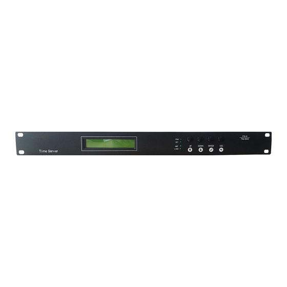
- Page 1 PTS-10 Time Server Reference Manual www.kyland.com...
-
Page 2: Table Of Contents
PTS Series Time Server Contents 1. Features........................2 1.1. Introduction....................2 2. LCD..........................3 2.1. Main Screen....................3 2.1.1. Time Infomation..................3 2.1.2. Status Infomation.................. 3 2.2. Indicator Light and Keys................3 2.3. Status Indication...................4 2.3.1. System Reference Time................. 4 2.3.2. Time Reference Status................4 2.3.3. -
Page 3: Features
Plus, PTS-10 supports network sync time protocols NTP/SNTP/ IEEE1588 V2.0. IEEE1588 works in several modes by the software configuration including grandmaster clock, slave clock and boundary clock. PTS-10 has LCD to show any status and do configuration by keyboard. Meanwhile, PTS-10 is designed to send timing source status and clock status to control center by IEC61850 MMS, IEC60870-T104, DNP3.0,... -
Page 4: Lcd
PTS Series Time Server 2.1. Main Screen The default main screen is shown as below: [Figure 2- 1] PTS-10 Main Screen The screen has two line characters. The top line always shows the time information. The bottom line shows time server status. -
Page 5: Status Indication
PTS Series Time Server Indicator light of front panel shows time server status. Name Description On: Power On; Off: Power Off On: Satellite Number >=4; Off: Satellite Number <4 On: Antenna is normal; Off: Antenna is abnormal Flash(1 second): Clock is locked; LOCK Flash(3 seconds):Clock is holded;... - Page 6 For IRIG-B time reference source, the first part of line named IRIG is shown below. [Figure ] Time Reference (IRIG-B) For PTP time reference source (i.e., the PTS-10 is working as PTP Slave Clock and Boundary Clock), the first part of line is named PTP. [Figure...
-
Page 7: Ptp Mode
PTS Series Time Server 2.3.3. PTP Mode The PTP mode is shown at last part of top line. The PTS-10 might work in one of the following modes: Master PTP Grandmaster Clock Slave PTP Slave Clock Boundary PTP Boundary Clock... - Page 8 PTS Series Time Server Use BDS as sync source, the display format is shown below: BDS:xx Ant:xx Fix:xx The amount of locked BDS satellites at present. BDS antenna status. Following is the status introduction: OK: antenna normal UV: low antenna power supply voltage NV: no antenna power supply voltage OC: antenna over current BDS fix mode.
- Page 9 PTS Series Time Server IRIG-B-xx-xxx Frame: xxx IRIG-B IRIG-B input format. Following is the format introduction: DC: IRIG-B DC AC: IRIG-B AC Modified Manchester Code Frame The number of IRIG-B input source frame [Figure ] Sync Source: IRIG-B-DC Use PTP as sync source, the display format is shown below: Off: xxxxxx Mode Delay: xxxxxx PTP Offset, the unit is ns...
-
Page 10: Operations
PTS Series Time Server Operations 3.1. Settings LCD screen might show data by ‘UP/DOWN’ key. Press ‘Enter’ key on any screen might enter setting screen. 3.1.1. Setting Options On main screen, select ‘Enter’ key to enter to setting configuration screen. [Figure ] Configuration Screen Name... -
Page 11: Sync Source Settings
PTS Series Time Server [Figure ] Configuration Screen Password Invalid Screen Input wrong password, the following tips will be shown: [Figure ] Invalid Password Screen Password Valid Screen Input correct password, the following tips will be shown: [Figure ] Valid Password Screen Sync Source Settings 3.2. - Page 12 PTS Series Time Server SAT2-T WA200 Auto/A-BDS/A- SAT1-M Satellite Mode GPS/A-GLN/F- Set satellite receiver working mode. SAT2-M BDS/F-GPS/F-GLN According to different antenna types SAT1-A Satellite Antenna and lengths, system implements time SAT2-A Compensation delay compensation. [Figure ] Sync Source Setting: Page 4,5 Name Description Parameter...
-
Page 13: Clock Settings
PTS Series Time Server B2CHA To set IRIG-B1/B2 input format, B1FOR including DC+ (positive polarity DC), DC- IRIG-B1/2 Format DC+/DC-/MC/AC B2FOR (negative polarity DC), MC (Manchester) and AC (modulated) IRIG-B signal. B1OFF Set time offset between IRIG-B and IRIG-B1/B2 UTC 0.00H B2OFF UTC. - Page 14 PTS Series Time Server Name Description Parameter Note MODE PTP Mode Master/Slave Set PTP working mode. /Boundary Delay Measurement Set clock delay measurement mode or PATH E2E / P2P / Disable Mode disable this function. Set the PTP sync message rate of PTP master clock.
-
Page 15: Output Settings
PTS Series Time Server VLAN-ID vLan ID 0~4095 Set vLan ID information. 3.6. Output Settings [Figure ] Output Setting Name Description Config serial output time signals. Config channel 1 output time signals. Config channel 2output time signals. Config channel 3 output time signals. Config channel 4 output time signals. -
Page 16: Irig-B-Ac Output
PTS Series Time Server [Figure ] O1~O5 Output Setting: Page 1 Name Description Parameter Note O1~O5 time Set the signal type for the O1~05. The O1~O5 PPS/IRIG/PPM/10M signals BDC means IRIG-B-DC signal. S-OFF IRIG-B Offset Set second offset for IRIG-B. PPS-OFF IRIG-B PPS Offset Set PPS offset for PPS1~5. - Page 17 PTS Series Time Server 192.168.0.111. Set ETH0 Subnet mask address, the Mask Address 255.255.255.0 default is 255.255.255.0. Network Mode Auto/Force Set ETH0 mode. [Figure ] Network Setting: Page 2 Name Description Parameter Note Set ETH1 IP address, the default is IP Address 192.168.1.111 192.168.1.111.
- Page 18 PTS Series Time Server Figure Index [Figure 1- 1] PTS-10 Time Server......................2 [Figure 2- 1] PTS-10 Main Screen......................3 [Figure 2- 2] PTS-10 Time Information....................3 [Figure 2- 3] PTS-10 Status Information....................3 [Figure 2- 4] System Reference Time...................... 4 [Figure 2- 5] Time Reference (GPS)......................4 [Figure 2- 6] Time Reference (BDS)......................4...
- Page 19 PTS Series Time Server [Figure 3- 11] NTP Setting: Page 1......................12 [Figure 3- 12] PTP Setting: Page 1......................12 [Figure 3- 13] PTP Setting: Page 2......................13 [Figure 3- 14] PTP Setting: Page 3......................13 [Figure 3- 15] PTP Setting: Page 4......................13 [Figure 3- 16] Output Setting........................
Need help?
Do you have a question about the PTS-10 and is the answer not in the manual?
Questions and answers