Table of Contents
Advertisement
Quick Links
Advertisement
Table of Contents

Related Manuals for effegibi effe AQUASTEAM SMART 30


Summary of Contents for effegibi effe AQUASTEAM SMART 30
- Page 1 AQUASTEAM SMART EASYSTEAM SMART Assembly instructions...
-
Page 2: Intended Use
INTRODUCTION SYMBOLS Whenever you see one of these symbols in the manual you must read the information given alongside as it is vital to ensure correct use of your steam generator. Failure to read and take into account the information could seriously compromise the safety of both objects and people. -
Page 3: Scope Of The Manual
SCOPE OF THE MANUAL This manual provides all the information required to ensure correct use and proper maintenance of the AQUASTEAM SMART/EASYSTEAM SMART generator. You must read this user and maintenance manual carefully before starting up the appliance for the first time; only then can you learn how to use our Steam Generator properly and in a short time. -
Page 4: Safety Instructions
SAFETY INSTRUCTIONS This manual is an integral part of the product, keep it carefully in an accessible place. Read this manual carefully before using the Hammam/Turkish bath. We recommend seeking medical advice before using the Hammam/Turkish bath. The equipment must not be used by children under the age of 8 and by people with reduced physical, sensorial or mental capabilities or those lacking the necessary experience or knowledge, other than under supervision, or if they have been... - Page 5 Prolonged use of the Turkish bath may raise the inner body temperature excessively and weaken its self-regulation capacity (hyperthermia). We recommend staying in the Turkish bath for a maximum of 15 minutes. Enter the Turkish bath cubicle once it is full of steam.
-
Page 6: Overall Dimensions
OVERALL DIMENSIONS Aquasteam Easysteam MAHA000371 AQUASTEAM / EASYSTEAM... -
Page 7: Pack Contents
PACK CONTENTS 1 Installation frame 2 AQUASTEAM SMART /EASYSTEAM SMART with bag of accessories 3 Polystyrene head protections 4 Bowl in white resin (only for AQUASTEAM SMART) 2 BAG OF ACCESSORIES N°4 N°4 N°4 N°1 N°1 N°1 N°1 N°1 AQUASTEAM / EASYSTEAM MAHA000371... -
Page 8: Installation
INSTALLATION 4.1. CHECKING THE ROOM FOR THE AQUASTEAM SMART /EASYSTEAM SMART COLUMN Check the height is 210mm x 535mm and check all around the appliance to make sure that the coating does not protrude; remove any excess. Silicone Put a complete strip of sili- cone (without gaps) around the base, between the box and the coating. - Page 9 4.2. SILICONE COATING ON THE FINISHING FRAME Put a complete strip of silicone (without gaps) around the entire inner layer of the frame to be brought in contact with the coating. ATTENTION! DO NOT REMOVE THE CONTAINMENT TEMPLATE IN ORDER TO AVOID DEFORMATIONS AQUASTEAM / EASYSTEAM MAHA000371...
- Page 10 4.3. INSERTING THE FINISHING FRAME Be careful not to reverse the top/ bottom position of the frame. Keep the hooks down. Insert the frame, putting the slots on the respective threaded steel pins. Once the silicone-coated frame has been positioned, tighten with the 4 flanged nuts in correspondence to the slots, taking care to keep it well against the coating and without deforming it.
- Page 11 4.4. CLEANING THE SILICONE Remove any silicone smears and check there are no gaps between the frame and the coat- ing: fill in any gaps with new silicone. The fixing nuts and the external surface of the frame must be clean and free of silicone residues and/or residues of masonry, glues and dust resulting from the installation.
- Page 12 DISASSEMBLING THE FRAME TEMPLATE After the silicone has dried, remove the 4 fixing screws of the containment template and remove it from the frame. MAHA000371 AQUASTEAM / EASYSTEAM...
- Page 13 CONNECTION TO THE MAINS SUPPLY (WATER - ELECTRICITY) WATER SYSTEM CONNECTION (LOADING) Remove the caps from the Aquasteam and outer casing Insert pipe + JG curve in the JG water inlet fitting of the outer casing and lock with the clip supplied.
- Page 14 Put the AQUASTEAM SMART / EASYSTEAM SMART column near where it is to be in- stalled. Insert the tube + JG curve into the filling connection of the AQUASTEAM SMART / EASYSTEAM SMART column. Push the tube fully and make sure it does not come off.
- Page 15 COLUMN POSITION While installing, the column should be supported by securing it as follows: Place the column on the lower supports ensuring that it is held upright and not let- ting it touch the covering below. Attach the steel cable on the column to the hook at the bottom of the outer casing.
-
Page 16: Connection To The Electrical Mains
CONNECTION TO THE ELECTRICAL MAINS The installation must be carried out only by qualified personnel in compliance with all the provisions contained in this manual and with IEC 64-8 and the respective electrical installation regulations of the local authorities. Follow the wiring diagrams. A circuit breaker permitting complete disconnection in accordance with overvoltage category III must be installed on the power line upstream of the appliance. -
Page 17: Electric Power Supply
ELECTRIC POWER SUPPLY AQUASTEAM / EASYSTEAM MAHA000371... -
Page 18: Optional Remote
OPTIONAL REMOTE Connector for the lamp and extra panel Remote connector Use the cable clamp to lock the lamp cable in place to avoid problems if it is pulled accidentally during installation or maintenance. DO NOT use the main power cable clamp. -
Page 19: Power Supply
POWER SUPPLY SINGLE-PHASE BLOCK DIAGRAM - OPTIONAL - REMOTE OPTIONAL - REMOTE POWER SUPPLY Open Door Common Signal Remote L3 L2 L1 Signal EQUIPOT. PANEL CROMO REMOTE (OPTIONAL) EQUIPOT. DOOR (OPTIONAL) 220-240 V ~ Power Ampere Fuse 3000 W 13.6 2.5 mm 4500 W 20.5... - Page 20 POWER SUPPLY THREE-PHASE BLOCK DIAGRAM - OPTIONAL - REMOTE POWER SUPPLY OPTIONAL - REMOTE Open Door Common Signal Remote Signal EQUIPOT. PANEL CROMO REMOTE (OPTIONAL) EQUIPOT. DOOR (OPTIONAL) 380-415 V 3N ~ Power Ampere Fuse 3000 W 1.5 mm 3x16A 4500 W 1.5 mm 3x20A...
-
Page 21: Power Cable
POWER CABLE SPECIFICATIONS AND OPTIONAL EXTRAS Obey the measurements and length of the cables given in the stripping diagrams below. The column is fitted with cable-clips that should be used to prevent the cable from sagging and coming loose from the terminal block, compromising insulation and operation. -
Page 22: Wiring Diagram
WIRING DIAGRAM & Correnti e sezione conduttori Amperage and Conductor 220-240 V ~ 380-415 V 3N ~ Power Ampere Ampere "" "" 3000 W 13,6 2.5 mm 1.5 mm "" 4500 W 20,5 4 mm 1.5 mm "" MAHA000371 AQUASTEAM / EASYSTEAM... -
Page 23: Junction Box Installation
JUNCTION BOX INSTALLATION Insert the electrical box through the slots and secure it with the appropriate nuts. AQUASTEAM / EASYSTEAM MAHA000371... - Page 24 INSERTING THE COLUMN After making the water and electrical connections, insert the column in its housing as pictured below: When closing the product, make sure that the steel cable is not pinched by the perimeter gasket and that the inlet hose matches the drain fitting. Both must remain within the volume of the outer casing.
- Page 25 INSERTING THE SCENT DEVICES To ensure the best result once you have put the essential oils into the container leave it slightly un- screwed. AQUASTEAM / EASYSTEAM MAHA000371...
-
Page 26: Start-Up Procedure
This phase will last for anything from 15 seconds to a few minutes during which the generator will install and recognise all the other devices (see Fig. A). Please note that the start-up sequence need only be repeated after additional optional EFFEGIBI features have been added at a later date. - Page 27 B The panel will display all the icons with a dimmer light. The control icons will flash, buttons “B” and “C” and the Effegibi logo will appear with a brighter light (see fig. C). fig. C Press the temperature controls, buttons “C” and “A”, firmly and in rapid succession, and they will glow brighter, and then the “ON/OFF”...
- Page 28 The “ON/OFF” button (shown in fig. D as number “3”) will start to flash. Now hold down the “HAMMAM/TURKISH BATH” button for at least 5 seconds (shown in fig. E as number “4”) until it starts flashing. The button will flash for a few minutes. During this phase the generator is recognising all the additional features installed.
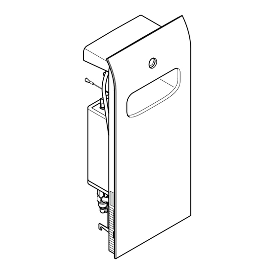
- Page 29 DESCRIPTION OF THE AQUASTEAM SMART Control panel Spring Scent devices *Adjustable fins Steam diffusion DESCRIPTION OF THE EASYSTEAM SMART Control panel Scent devices *Adjustable fins Steam diffusion *WARNING to avoid burns, direct the fins only with the product off. AQUASTEAM / EASYSTEAM MAHA000371...
- Page 30 Note ....................................................................................................................................................................................................................................................................................................................................................................................................................................................................................................................................................................................................................................................................................................................MAHA000371 AQUASTEAM / EASYSTEAM...
- Page 32 Via Gallo 769 tel +39 0547 372881 www.effegibi.it 47522 Cesena (FC) fax +39 0547 372924 info@effegibi.it Italy...
Need help?
Do you have a question about the effe AQUASTEAM SMART 30 and is the answer not in the manual?
Questions and answers
How do I adjust the temperature on my device?