ALTUS Nexto Series User Manual
Hide thumbs
Also See for Nexto Series:
- User manual (392 pages) ,
- Manual (24 pages) ,
- User manual (300 pages)
Table of Contents
Advertisement
Quick Links
Advertisement
Table of Contents

Subscribe to Our Youtube Channel
Related Manuals for ALTUS Nexto Series


Summary of Contents for ALTUS Nexto Series
- Page 1 User Manual Nexto Serie CPU NX3005 MU214617 Rev. B May 27, 2022...
- Page 2 General Supply Conditions No part of this document may be copied or reproduced in any form without the prior written consent of Altus Sistemas de Automação S.A. who reserves the right to carry out alterations without prior advice. According to current legislation in Brazil, the Consumer Defense Code, we are giving the following information to clients who use our products, regarding personal safety and premises.
-
Page 3: Table Of Contents
1.1. Nexto Series .......... - Page 4 CONTENTS 3.4.1. RS-485 Communication without termination ......21 3.4.2. RS-485 Communication with Internal Termination ..... . . 22 3.4.3.
- Page 5 CONTENTS 4.14.5. GVL Disables ......... . 52 4.14.6.
- Page 6 CONTENTS 5.4. NX5000 Module Configuration ........86 5.5.
- Page 7 CONTENTS 5.5.9.1.3. Mapping Configuration – Configuration via Symbolic Mapping ..142 5.5.9.2. MODBUS Server Ethernet Protocol Configuration via Direct Representation (%Q) 5.5.9.2.1. General Parameters of MODBUS Server Protocol – Configuration via Di- rect Representation (%Q) .
- Page 8 CONTENTS 5.6.1. MODBUS Server ........189 5.6.1.1.
- Page 9 CONTENTS 5.12.3. Private MIB ......... . . 233 5.12.4.
-
Page 10: Introduction
Nexto Series uses an advanced technology in its bus, which is based on a high speed Ethernet interface, allowing input and output information and data to be shared between several controllers inside the same system. The system can be easily divided and distributed throughout the whole field, allowing the use of bus expansion with the same performance of a local module, turning possible the use of every module in the local frame or in the expansion frames with no restrictions. -
Page 11: Innovative Features
Figure 2: Nexto Series – Overview 1.2. Innovative Features Nexto Series brings to the user many innovations regarding utilization, supervision and system maintenance. These features were developed focusing a new concept in industrial automation. Battery Free Operation: Nexto Series does not require any kind of battery for memory maintenance and real time clock operation. -
Page 12: Documents Related To This Manual
ETD – Electronic Tag on Display: Another exclusive feature that Nexto Series brings to PLCs is the Electronic Tag on Display. This new functionality brings the process of checking the tag names of any I/O pin or module used in the system directly to the CPU’s graphic display. -
Page 13: Visual Inspection
Such procedure guaranties that the module static energy limits are not exceeded. It’s important to register each received equipment serial number, as well as software revisions, in case they exist. This information is necessary, in case the Altus Technical Support is contacted. -
Page 14: Technical Support
1. INTRODUCTION 1.5. Technical support For Altus Technical Support contact in São Leopoldo, RS, call +55 51 3589-9500. For further information regarding the Altus Technical Support existent on other places, see https://www.altus.com.br/en/ or send an email to altus@altus.com.br. If the equipment is already installed, you must have the following information at the moment of support requesting:... -
Page 15: Technical Description
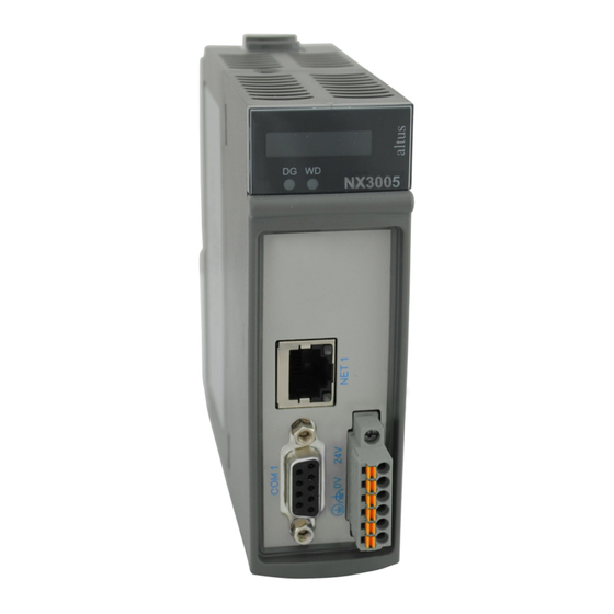
Description Diagnostics LED Watchdog LED Table 2: LEDs Description Nexto Series CPUs has two switches available to the user. The table below shows the description of these switches. For further information regarding the diagnostics switch, see sections One Touch Diag. -
Page 16: Common General Features
2. TECHNICAL DESCRIPTION Interfaces Description RJ45 communication connector 10/100Base-TX stan- dard. Allows the point to point or network communi- NET 1 cation. For further utilization information, see Ethernet Interfaces Configuration section. DB9 female connector for RS-232 communication stan- dard. Allows the point to point or network. For further COM 1 utilization information, see Serial Interfaces Configura-... -
Page 17: Memory
2. TECHNICAL DESCRIPTION NX3005 Maximum number of I/O modules on the bus Maximum number of additional Ethernet TCP/IP interface modules Ethernet TCP/IP interface redundancy sup- port Maximum number of PROFIBUS-DP network (using master modules PROFIBUS-DP) PROFIBUS-DP network redundancy support Redundancy support (half-clusters) Hot Swap support Event oriented data reporting (SOE) Protocol... - Page 18 2. TECHNICAL DESCRIPTION NX3005 Addressable input variables memory (%I) 32 Kbytes Addressable output variables memory (%Q) 32 Kbytes Direct representation variable memory (%M) 16 Kbytes Symbolic variable memory 3 Mbytes Maximum amount of memory configurable as 7.5 Kbytes retentive or persistent Full Redundant Data Memory Direct representation input variable mem- ory (%I)
-
Page 19: Protocols
2. TECHNICAL DESCRIPTION Command VAR RETAIN VAR PERSISTENT Reset warm / Power on/off cycle Reset cold Reset origin Remove CPU or Power Supply from the rack while energized Download Online change Reboot PLC Clean All Reset Process (IEC 60870-5-104) Table 7: Post-command Variable Behavior In the case of Clean All command, if the application has been modified so that persistent variables have been removed, inserted into the top of the list or otherwise have had its modified type, the value of these variables is lost (when prompted by the tool MasterTool to download). -
Page 20: Serial Interfaces
2. TECHNICAL DESCRIPTION NX3005 Interface EtherNet/IP Adapter NET1 MQTT Client NET1 SNTP Client (for clock syn- NET1 chronism) PROFINET Controller NET1 PROFINET Device Table 8: Protocols Note: PROFINET Controller: Enabled for use on a simple (not ring) network with up to 8 devices. For larger applications, consult technical support. -
Page 21: Ethernet Interfaces
2. TECHNICAL DESCRIPTION 2.2.5. Ethernet interfaces 2.2.5.1. NET 1 NET 1 Connector Shielded female RJ45 Auto crossover Maximum cable length 100 m Cable type UTP or ScTP, category 5 Baud rate 10/100 Mbps Physical layer 10/100 BASE-TX (Full Duplex) Data link layer LLC (Logical Link Control) Network layer IP (Internet Protocol)) -
Page 22: Environmental Characteristics
2.3. Compatibility with Other Products To develop an application for Nexto Series CPUs, it is necessary to check the version of MasterTool IEC XE. The following table shows the minimum version required (where the controllers were introduced) and the respective firmware version at that... -
Page 23: Application Times
< 5000 Table 14: Instruction Times 2.4.3. Initialization Times Nexto Series CPUs have initialization times of 50 s, and the initial screen with the NEXTO logo (Splash) is presented after 20 s from the power switched on. 2.4.4. Interval Time... -
Page 24: Physical Dimensions
2. TECHNICAL DESCRIPTION 2.5. Physical Dimensions Dimensions in mm. Figure 4: NX3004 and NX3005 CPU Physical Dimensions... -
Page 25: Purchase Data
AL-2306: Two shielded twisted pairs cable without connectors, used for networks based on RS-485 or CAN. AL-2319: Two RJ45 connectors for programming the CPUs of the Nexto Series and Ethernet point-to-point with another device with Ethernet interface communication. - Page 26 2. TECHNICAL DESCRIPTION AL-1763: Cable with one DB9 male connector and terminal block for communication between CPUs of the Nexto Series and products with RS-485/RS-422 standard terminal block. NX9202/NX9205/NX9210: Cables used for Ethernet communication and to interconnect the bus expansion modules.
-
Page 27: Installation
3. INSTALLATION 3. Installation This chapter presents the necessary proceedings for the Nexto Series CPUs physical installation, as well as the care that should be taken with other installation within the panel where the CPU is been installed. CAUTION: If the equipment is used in a manner not specified by in this manual, the protection provided by the equipment may be impaired. -
Page 28: Ethernet Network Connection
3.3.3. Network Cable Installation Nexto Series CPUs Ethernet ports, identified on the panel by NET, have standard pinout which are the same used in PCs. The connector type, cable type, physical level, among other details regarding the CPU and the Ethernet network device are... -
Page 29: Serial Network Connection
3. INSTALLATION Figure 6: RJ45 Female Connector Signal Description TXD + Data transmission, positive TXD - Data transmission, negative RXD + Data reception, positive Not used Not used RXD - Data reception, negative Not used Not used Table 18: RJ45 Female Connector Pinout - 10BASE-TE and 100BASE-TX The interface can be connected in a communication network through a hub or switch, or straight from the communication equipment. -
Page 30: Communication Without Termination
3. INSTALLATION Figure 7: DB9 Female Connector Sign Description Not used Term+ Internal Termination, positive TXD+ Data Transmission, positive RXD+ Data Reception, positive Negative Reference for External Termination Positive Reference for External Termination Term- Internal Termination, negative TXD- Data Transmission, negative RXD- Data Reception, negative Table 19: COM 1 (NX3004/NX3005) and COM 2 (NX3010/NX3020/NX3030) -
Page 31: Communication With Internal Termination
3. INSTALLATION Figure 8: RS-485 Connections without Termination Diagram Diagram Note: 1. The not connected terminals must be insulated so they do not make contact with each other. 3.4.2. RS-485 Communication with Internal Termination In order to connect in a RS-485 network using the internal termination, the cable AL-1763 identified terminals must be connected in the respective device terminals, as shown on table below. -
Page 32: Communication With External Termination
3. INSTALLATION Diagram Note: 1. The not connected terminals must be insulated so they do not make contact with each other. 3.4.3. RS-485 Communication with External Termination In order to connect to a RS-485 network wih external termination, the AL-1763 cable identified terminals must be con- nected in the respective device terminals according to the table below. -
Page 33: Communication With Internal Termination
3. INSTALLATION AL-1763 terminals CPU terminal signals Not connected Not connected Not connected Table 23: RS-422 Connections without Termination The figure diagram below indicates how the AL-1763 connection terminals should be connected in the device terminals. Figure 11: Connections without Termination Diagram Diagram Note: 1. -
Page 34: Communication With External Termination
3. INSTALLATION Figure 12: RS-422 Connections with Termination Diagram Diagram Note: 1. The not connected terminals must be insulated so they do not make contact with each other. 3.4.6. RS-422 Communication with External Termination In order to connect in a RS-422 network using interface external termination, the cable AL-1763 identified terminals must be connected in the respective device terminals, as shown on table below. -
Page 35: Network Example
3.5.1. Module Installation on the Main Backplane Rack Nexto Series has an exclusive method for connecting and disconnecting modules on the bus which does not require much effort from the operator and guarantee the connection integrity. For further information regarding Nexto Series products fixation, please see Nexto Series User Manual –... -
Page 36: Initial Programming
4. INITIAL PROGRAMMING 4. Initial Programming The main goal of this chapter is to help the programming and configuration of Nexto Series CPUs, allowing the user to take the first steps before starting to program the device. Nexto Series CPU uses the standard IEC 61131-3 for language programming, which are: IL, ST, LD, SFC and FBD, and besides these, an extra language, CFC. - Page 37 4. INITIAL PROGRAMMING SIGNIFICANCE OVERLAPPING Byte Word DWord LWord Byte Word DWord %QX0.7 %QX0.6 %QX0.5 %QX0.4 %QB00 %QX0.3 %QX0.2 %QX0.1 %QX0.0 %QX1.7 %QX1.6 %QX1.5 %QX1.4 %QB01 %QX1.3 %QX1.2 %QX1.1 %QX1.0 %QX2.7 %QX2.6 %QX2.5 %QX2.4 %QB02 %QX2.3 %QX2.2 %QX2.1 %QX2.0 %QX3.7 %QX3.6 %QX3.5 %QX3.4...
-
Page 38: Project Profiles
4. INITIAL PROGRAMMING The table above shows the organization and memory access, illustrating the significance of bytes and the disposition of other variable types, including overlapping. 4.2. Project Profiles A project profile in the MasterTool IEC XE consists in an application template together with a group of verification rules which guides the development of the application, reducing the programming complexity. -
Page 39: Basic
4. INITIAL PROGRAMMING 4.2.2. Basic In the Basic Project Profile, the application has one user task of the Continuous type called MainTask, which executes the program in a continuous loop (with no definition of cycle time) with priority fixed in 13 (thirteen). This task is responsible for the execution of a single programming unit POU called MainPrg. -
Page 40: Custom
The Custom project profile allows the developer to explore all the potential of the Runtime System implemented in the Nexto Series central processing units. No functionality is disabled; no priority, task and programs association or nomenclatures are imposed. The only exception is for MainTask, which must always exist with this name in this Profile. -
Page 41: General Table
4. INITIAL PROGRAMMING This profile may further include an interruption task, called TimeInterruptTask00, with a higher priority than the MainTask, and hence, can interrupt its execution at any time. Tasks Priority Type Interval Event MainTask MainPrg Cyclic 20 ms TimeInterruptTask00 TimeInterruptPrg00 Cyclic 4 ms... -
Page 42: Maximum Number Of Tasks
4. INITIAL PROGRAMMING 4.2.8. Maximum Number of Tasks The maximum number of tasks that the user can create is only defined for the Custom profile, the only one which has this permission. The others already have their tasks created and configured. However, the tasks that will be created must use the following prefixes, according to the type of each of the tasks: CyclicTaskxx, TimeInterruptTaskxx, ExternInterruptTaskxx, where xx represents the number of the task that being created. - Page 43 4. INITIAL PROGRAMMING Figure 15: CPU Configuration Besides that, by double-clicking on CPU’s NET 1 icon, it’s possible to configure the Ethernet interface that will be used for communication between the controller and the software MasterTool IEC XE. Figure 16: Configuring the CPU Communication Port The configuration defined on this tab will be applied to the device only when sending the application to the device (down- load), which is described further on sections Finding the Device...
-
Page 44: Libraries
The insertion procedure and more information about available libraries must be found in the MasterTool Programming Manual – MP399609. 4.5. Inserting a Protocol Instance The Nexto Series CPUs, as described in the Protocols section, offers several communication protocols. Except for the... -
Page 45: Modbus Ethernet
4. INITIAL PROGRAMMING Figure 18: Selecting the Protocol 4.5.2. MODBUS Ethernet The first step to configure the MODBUS Ethernet, in client mode, is to include the instance in the desired NET (in this case, NET 1, as the CPU NX3010 has only one Ethernet interface). Click on the NET with the mouse right button and select Add Device..., as shown on figure below. - Page 46 4. INITIAL PROGRAMMING Figure 19: Adding the Instance After that, the available protocols for the user will appear on the screen. Define the protocol configuration mode selecting MODBUS Symbol Client, for symbolic mapping setting or MODBUS Client, for direct addressing (%Q) and click on Add Device, as depicted on figure below.
-
Page 47: Servidor Iec 60870-5-104
4. INITIAL PROGRAMMING Figure 20: Selecting the Protocol 4.5.3. Servidor IEC 60870-5-104 The first step to configure the IEC 60870-5-104 communication driver, in server mode, is to include the instance under the desired NET (CPU NX3030 owns two Ethernet interfaces, NET 1 and NET 2). Click with the right button over the NET and select Add Device..., according the figure below:... - Page 48 4. INITIAL PROGRAMMING Figure 21: Adding a Server IEC 60870-5-104 Instance After that, will show up the available protocols screen. In this case, select IEC 60870-5-104 > IEC 60870-5-104 Server > IEC 60870-5-104 Server and click on Add Device, according to figure below.
- Page 49 4. INITIAL PROGRAMMING Figure 22: Selecting the Server IEC 60870-5-104 Protocol At last the user must click with the right button over the inserted protocol IEC 60870-5-104 Server inserted in the NET1, one or more Clients, according to figure below.
-
Page 50: Finding The Device
4. INITIAL PROGRAMMING Figure 23: Inserting a Client of Server IEC 60870-5-104 Protocol 4.6. Finding the Device To establish the communication between the CPU and MasterTool IEC XE, first it’s necessary to find and select the desired device. The configuration of this communication is located on the object Device on device tree, on Communication Settings tab. - Page 51 4. INITIAL PROGRAMMING Figure 24: Finding the CPU If there is no gateway previously configured, it can be included by the button Add gateway, using the default IP address localhost to use the gateway resident on the station or changing the IP address to use the device internal gateway. Next, the desired controller must be selected by clicking on Set active path.
-
Page 52: Login
4. INITIAL PROGRAMMING Figure 26: Easy Connection This command performs a MAC level communication with the device, allowing to permanently change the configuration of the CPU’s Ethernet interface, independently of the IP configuration of the station and from the one previously configured on the device. - Page 53 4. INITIAL PROGRAMMING After the command execution, some user interface messages may appear, which are presented due to differences between an old project and the new project been sent, or simply because there was a variation in some variable. If the Ethernet configuration of the project is different from the device, the communication may be interrupted at the end of download process when the new configuration is applied on the device.
-
Page 54: Run Mode
4. INITIAL PROGRAMMING If the new application contains changes on the configuration, the online change will not be possible. In this case, the MasterTool IEC XE requests whether the login must be executed as download (stopping the application) or if the operation must be cancelled. -
Page 55: Stop Mode
4. INITIAL PROGRAMMING Figure 33: Starting the Application The figure below shows the application in execution. In case the POU tab is selected, the created variables are listed on a monitoring window, in which the values can be visualized and forced by the user. Figure 34: Program running If the CPU already have a boot application internally stored, it goes automatically to Run Mode when the device is powered on, with no need for an online command through MasterTool IEC XE. -
Page 56: Writing And Forcing Variables
4. INITIAL PROGRAMMING Figure 35: Stopping the Application In case the CPU is initialized without the stored application, it automatically goes to Stop Mode, as it happens when a software exception occurs. 4.10. Writing and Forcing Variables After Logging into a PLC, the user can write or force values to a variable of the project. The writing command (CTRL + F7) writes a value into a variable and this value could be overwritten by instructions executed in the application. -
Page 57: Project Upload
Figure 36: Finalizing the online communication with the CPU 4.12. Project Upload Nexto Series CPUs are capable to store the source code of the application on the internal memory of the device, allowing future retrieval (upload) of the complete project and to modify the application. -
Page 58: Cpu Operating States
4. INITIAL PROGRAMMING Next, just select the desired CPU and click OK, as shown on figure below. Figure 38: Selecting the CPU To ensure that the project loaded in the CPU is identical and can be accessed in other workstations, consult the chapter Projects Download/Login Method without Project Differences at the MasterTool IEC XE User Manual MT8500 - MU299609. -
Page 59: Exception
4. INITIAL PROGRAMMING 4.13.4. Exception When a CPU is in Exception it indicates that some improper operation occurred in one of the application active tasks. The task which caused the Exception will be suspended and the other tasks will pass for the Stop mode. It is only possible to take off the tasks from this state and set them in execution again after a new CPU start condition. -
Page 60: Startprg Program
4. INITIAL PROGRAMMING isFirstCycle : BOOL := TRUE; END_VAR SpecialVariablesPrg(); IF isFirstCycle THEN StartPrg(); isFirstCycle := FALSE; ELSE UserPrg(); END_IF; MainPrg call other two POUs of program type, named StartPrg and UserPrg. While the UserPrg is always called, the StartPrg is only called once in the PLC application start. To the opposite of MainPrg program, that must not be modified, the user can change the StartPrg and UserPrg programs. -
Page 61: Gvl Disables
4. INITIAL PROGRAMMING Figure 39: System_Diagnostics GVL in Online Mode 4.14.5. GVL Disables The Disables GVL contains the MODBUS Master/Client by symbolic mapping requisition disabling variables. It is not mandatory, but it is recommended to use the automatic generation of these variables, which is done clicking in the button Generate Disabling Variables in device requisition tab. -
Page 62: Gvl Ioqualities
4. INITIAL PROGRAMMING VAR_GLOBAL MODBUS_Device_DISABLE_0001 : BOOL; MODBUS_Device_DISABLE_0002 : BOOL; MODBUS_Device_DISABLE_0003 : BOOL; MODBUS_Device_1_DISABLE_0001 : BOOL; MODBUS_Device_1_DISABLE_0002 : BOOL; END_VAR The automatic generation through button Generate Disabling Variables only create variables, and don’t remove automati- cally. This way, in case any relation is removed, its respective disabling variable must be removed manually. The Disables GVL is editable, therefore the requisition disabling variables can be created manually without need of fol- lowing the model created by the automatic declaration and can be used both ways at same time, but must always be of BOOL type. -
Page 63: Gvl Module_Diagnostics
4. INITIAL PROGRAMMING 4.14.7. GVL Module_Diagnostics The Module_Diagnostics GVL contains the diagnostics variables of the I/O modules used in the project, except by the CPU and communication drivers. This GVL isn’t editable and the variables are automatically declared with type specified by the module, to which it belongs, when that is added to the project. - Page 64 4. INITIAL PROGRAMMING [Device Name]_QUALITY_[Mapping Number]: LibDataTypes.QUALITY; Where: Device Name: Name that appear at the Tree View to the device. Mapping Number: Number of the mapping that was declared on the device mapping table, following the up to down sequence, starting with 0001. ATTENTION: It is not possible to associate quality variables to the direct representation MODBUS Mas- ter/Client drivers’...
-
Page 65: Gvl Reqdiagnostics
4. INITIAL PROGRAMMING Figure 42: Qualities GVL in Online Mode 4.14.9. GVL ReqDiagnostics The ReqDiagnostics GVL contains the requisition diagnostics variables of symbolic mapping MODBUS Master/Client. It is not mandatory, but recommended the use of these variables’ automatic generation, what is done by clicking in the button Generate Diagnostics Variables in device requests tab. -
Page 66: Prepare_Start Function
4. INITIAL PROGRAMMING ATTENTION: The requisition diagnostics variables of direct mapping MODBUS Master/Client are de- clared at System_Diagnostics GVL. Example: Device.Application.ReqDiagnostics VAR_GLOBAL MODBUS_Device_REQDG_0001 : NXMODBUS_DIAGNOSTIC_STRUCTS. T_DIAG_MODBUS_RTU_MAPPING_1; MODBUS_Device_REQDG_0002 : NXMODBUS_DIAGNOSTIC_STRUCTS. T_DIAG_MODBUS_RTU_MAPPING_1; MODBUS_Device_REQDG_0003 : NXMODBUS_DIAGNOSTIC_STRUCTS. T_DIAG_MODBUS_RTU_MAPPING_1; MODBUS_Device_1_REQDG_0001 : NXMODBUS_DIAGNOSTIC_STRUCTS. T_DIAG_MODBUS_ETH_MAPPING_1; MODBUS_Device_1_REQDG_0002 : NXMODBUS_DIAGNOSTIC_STRUCTS. T_DIAG_MODBUS_ETH_MAPPING_1;... -
Page 67: Prepare_Stop Function
4. INITIAL PROGRAMMING 4.14.11. Prepare_Stop Function In this POU, the PrepareStop system event function is defined. It belongs to the communication task and is called before stopping the application. When there is active communication with the PLC, it is possible to observe the event status and the call count in the System Events tab in the Task Configuration object. -
Page 68: Configuration
5. CONFIGURATION 5. Configuration The Nexto Series CPUs are configured and programmed through the MasterTool IEC XE software. The configuration made defines the behavior and utilization modes for peripherals use and the CPUs special features. The programming represents the Application developed by the user. - Page 69 5. CONFIGURATION Settings Description Standard Options - Denabled, only for de- Enabled, clared modules match - Disabled (with match con- consistency. Hot Swap Mode Module hot swap mode sistency) (may vary - Disabled, no match consis- according to tency CPU model) - Enabled, with match con- sistency only for declared modules...
-
Page 70: Hot Swap
MainTask anymore. 5.1.1.1. Hot Swap Nexto Series CPUs have the possibility of I/O modules change in the bus with no need for system turn off and without information loss. This feature is known as hot swap. -
Page 71: Hot Swap Disabled
5. CONFIGURATION Reset Origin is carried out, it will be necessary to perform the download so that the CPU can return to the normal state (Run). The Reset Warm, Reset Cold and Reset Origin commands can be done by MasterTool IEC XE in the Online menu. The CPU will remain in normal Run even if find a module not declared on the bus. -
Page 72: How To Do The Hot Swap
5. CONFIGURATION 5.1.1.1.7. How to do the Hot Swap CAUTION: Before performing the Hot Swap it is important to discharge any possible static energy accu- mulated in the body. To do that, touch (with bare hands) on any metallic grounded surface before handling the modules. - Page 73 5. CONFIGURATION Enabled, with Startup Enabled, Disabled, Disabled, Enabled, Consistency without for declared without Condition with Startup Disabled for Declared Startup modules Startup Consistency Modules Consistency only Consistency Only clared Blinks 2x Blinks 2x Blinks 2x Blinks 4x Blinks 2x Blinks 4x module Application:...
-
Page 74: Retain And Persistent Memory Areas
5. CONFIGURATION 5.1.1.2. Retain and Persistent Memory Areas The Nexto CPU allows the use of symbolic variables and output variables of direct representation as retentive or persistent variables. The output variables of direct representation which will be retentive or persistent must be declared in the CPU General Parameters, as described at Configuration. -
Page 75: Tcp Configurations
In addition, it is important to stress that there’s a maximum quantity of attempts for the Nexto Series CPUs. This number is set in five attempts before the connection is set up and in three attempts after that. - Page 76 5. CONFIGURATION ACK sending delay: defines the maximum time waited by the interface for the TCP ACK transmitting. This ACK is responsible for the message receiving conformation, in case of MODBUS, by the destiny device. The set of this field decreases the amount of messages circling through the network.
-
Page 77: Project Parameters
5. CONFIGURATION 5.1.1.4. Project Parameters The CPU project parameters are related to the configuration for input/output refreshing at the task that they are used of the project tasks and consistency of the retentive and persistent area in %Q. Configuration Description Default Options Performs the consistency of... -
Page 78: Time Synchronization
Figure 49: ExternInterruptTask00 Configuration Screen 5.1.3. Time Synchronization For the time synchronization, Nexto Series CPUs use the SNTP (Simple Network Time Protocol) or the synchronism through IEC 60870-5-104. - Page 79 5. CONFIGURATION To use the time sync protocols, the user must set the following parameters at Synchronism tab, accessed through the CPU, in the device tree: Figure 50: SNTP Configuration Configuration Description Default Options Time zone of the user loca- Time Zone (hh:mm) tion.
-
Page 80: Iec 60870-5-104
5. CONFIGURATION 5.1.3.1. IEC 60870-5-104 In case the synchronism is through IEC 60870-5-104 protocol, the user must enable the time sync at the protocol con- figuration screen to receive the clock synchronization. To set this option on the device, check the parameter Enable Time Synchronization available at the Application Layer section. -
Page 81: Internal Points
5. CONFIGURATION 5.1.4. Internal Points A communication point is storage on the CPU memory under form of two distinct variables. One represents the point’s value (type BOOL, BYTE, WORD, etc. . . ), while another, represents its quality (type QUALITY). Internal Points are those which the value and the quality are calculated internally by the user application, that is, they don’t have an external origin like occur with points linked to IEDs (Communication drivers of type Master/Client) or to local I/O modules. -
Page 82: Quality Conversions
The Standards IEC 61850, DNP3 and IEC104 have their own formats to representation of point’s quality information. The Nexto Series, by its turn, have its own quality format (but quite similar to IEC 61850) called Internal Quality. This format is defined by type QUALITY (library LibRtuStandard) and it is used internally to quality storage, allowing to be done conversion between protocols without information loss. -
Page 83: Internal Quality
5. CONFIGURATION 5.1.4.1.1. Internal Quality This is the QUALITY structure. The table shows detailed each of its components. Name Type Description The RESTART flag indicates that the data FLAG_RESTART BOOL haven’t been updated by the field since the device’s reset. Indicates there is a communication failure FLAG_COMM_FAIL BOOL... -
Page 84: Iec 60870-5-104 Conversion
IED) Table 42: QUALITY Structure 5.1.4.1.2. IEC 60870-5-104 Conversion The tables below presents respectively the digital, analog and counters internal point’s conversion to IEC 60870-5-104 of Nexto Series available to MT8500. Internal-> IEC 60870-5-104 Digital Internal Quality Flags... -
Page 85: Modbus Internal Quality
5. CONFIGURATION Internal -> IEC 60870-5-104 Analog Internal Quality Flags VALIDITY IEC 60870-5-104 Quality FLAG_INACCURATE INVALID FLAG_OLD_DATA NOT TOPICAL FLAG_FAILURE INVALID FLAG_OPERATOR_BLOCKED BLOCKED FLAG_TEST VALIDITY_INVALID INVALID Table 44: Analog Points Conversion Internal to IEC 60870-5-104 Internal -> IEC 60870-5-104 Counters Internal Quality Flags VALIDITY... -
Page 86: Local Bus I/O Modules Quality
5. CONFIGURATION Resulting Quality Resulting VALIDITY Description It has received an exception FLAG_FAILURE VALIDITY_INVALID response and the point kept FLAG_RESTART its initial value. It has received an exception FLAG_FAILURE VALIDITY_QUESTIONABLE response, but the point has a FLAG_OLD_DATA valid old value. FLAG_RESTART Device stopped. -
Page 87: Profibus Digital Input Quality
5. CONFIGURATION to make any needed adaptation and change to fit to its application. ATTENTION: For the routines, presented in sequence, correct functioning it is necessary to enable Status in Diagnose in the PROFIBUS slaves. The development of PROFIBUS I/O modules quality points update routine must began from quality variables declaration and initialization, from a GVL: VAR_GLOBAL QUALITY_PB_NX1005_I:... -
Page 88: Profibus Digital Output Quality
5. CONFIGURATION // If the point have ever been updated once ... IF NOT QUALITY_PB_NX1005_I.FLAGS.FLAG_RESTART THEN QUALITY_PB_NX1005_I.FLAGS.FLAG_OLD_DATA:= TRUE; END_IF END_IF END_IF // In PROFIBUS communication failure with the PROFIBUS slave ... ELSE QUALITY_PB_NX1005_I.VALIDITY:= VALIDITY_INVALID; QUALITY_PB_NX1005_I.FLAGS.FLAG_COMM_FAIL:= TRUE; QUALITY_PB_NX1005_I.FLAGS.FLAG_FAILURE:= FALSE; // If the point have ever been updated once ... IF NOT QUALITY_PB_NX1005_I.FLAGS.FLAG_RESTART THEN QUALITY_PB_NX1005_I.FLAGS.FLAG_OLD_DATA:= TRUE;... -
Page 89: Profibus Analog Input Quality
5. CONFIGURATION QUALITY_PB_NX1005_O.FLAGS.FLAG_FAILURE:= TRUE; // If the point have ever been updated once ... IF NOT QUALITY_PB_NX1005_O.FLAGS.FLAG_RESTART THEN QUALITY_PB_NX1005_O.FLAGS.FLAG_OLD_DATA:= TRUE; END_IF END_IF END_IF // In PROFIBUS communication failure with the PROFIBUS slave ... ELSE QUALITY_PB_NX1005_O.VALIDITY:= VALIDITY_INVALID; QUALITY_PB_NX1005_O.FLAGS.FLAG_COMM_FAIL:= TRUE; QUALITY_PB_NX1005_O.FLAGS.FLAG_FAILURE:= FALSE; // If the point have ever been updated once ... - Page 90 5. CONFIGURATION DG_NX6000_8_AI_Voltage_Current.tDetailed.tAnalogInput_00.bOpenLoop = FALSE THEN QUALITY_PB_NX6000.VALIDITY:= VALIDITY_GOOD; QUALITY_PB_NX6000.FLAGS.FLAG_RESTART:= FALSE; QUALITY_PB_NX6000.FLAGS.FLAG_FAILURE:= FALSE; QUALITY_PB_NX6000.FLAGS.FLAG_OLD_DATA:= FALSE; QUALITY_PB_NX6000.FLAGS.FLAG_INACCURATE:= FALSE; QUALITY_PB_NX6000.FLAGS.FLAG_OUT_OF_RANGE:= FALSE; ELSE // Condition to turns on imprecision indication // (check first, because invalid validity must prevail) IF DG_NX6000_8_AI_Voltage_Current.tGeneral.bCalibrationError = TRUE THEN QUALITY_PB_NX6000.VALIDITY:= VALIDITY_QUESTIONABLE; QUALITY_PB_NX6000.FLAGS.FLAG_INACCURATE:= TRUE;...
-
Page 91: Profibus Analog Output Quality
5. CONFIGURATION END_IF END_IF // In PROFIBUS communication failure with the PROFIBUS slave ... ELSE QUALITY_PB_NX6000.VALIDITY:= VALIDITY_INVALID; QUALITY_PB_NX6000.FLAGS.FLAG_COMM_FAIL:= TRUE; QUALITY_PB_NX6000.FLAGS.FLAG_FAILURE:= FALSE; // If the point have ever been updated once ... NOT QUALITY_PB_NX6000.FLAGS.FLAG_RESTART AND NOT DG_NX6000_8_AI_Voltage_Current.tDetailed.tAnalogInput_00.bOpenLoop THEN QUALITY_PB_NX6000.FLAGS.FLAG_OLD_DATA:= TRUE; END_IF END_IF 5.1.4.1.9. - Page 92 5. CONFIGURATION QUALITY_PB_NX6100.FLAGS.FLAG_FAILURE:= FALSE; QUALITY_PB_NX6100.FLAGS.FLAG_INACCURATE:= FALSE; QUALITY_PB_NX6100.FLAGS.FLAG_OLD_DATA:= FALSE; ELSE // Condition to turns on imprecision indication // (check first, because invalid validity must prevail) IF DG_NX6100_4_AO_Voltage_Current.tGeneral.bCalibrationError = TRUE THEN QUALITY_PB_NX6100.VALIDITY:= VALIDITY_QUESTIONABLE; QUALITY_PB_NX6100.FLAGS.FLAG_INACCURATE:= TRUE; ELSE QUALITY_PB_NX6100.FLAGS.FLAG_INACCURATE:= FALSE; END_IF // Condition to turns on general failure indication (priority) IF (DG_NX5110.tPbusHeadA.dwModuleNotPresent AND SHL(1, 4)) >...
-
Page 93: Serial Interfaces Configuration
5. CONFIGURATION 5.2. Serial Interfaces Configuration 5.2.1. COM 1 The COM 1 communication interface is composed by a DB9 female connector for the RS-422 and RS-485 standards. It allows the point to point or network communication in the open protocols MODBUS RTU slave or MODBUS RTU master. When using the MODBUS master/slave protocol, some of these parameters (such as Serial Mode, Data Bits, UART RX Threshold and Serial Events) are automatically adjusted by MasterTool for the correct operation of this protocol. -
Page 94: Advanced Configurations
Nexto CPUs can provide more local Ethernet interfaces. The NX3005 CPU has only the NET 1 interface. In addition to the local Ethernet interfaces, the Nexto Series also provides remote Ethernet interfaces by including the NX5000 module. The NX5000 modules have only the NET 1 interface. -
Page 95: Reserved Tcp Ports
5. CONFIGURATION TCP Client, MODBUS TCP Server and MODBUS RTU via TCP Server. The parameters which must be configured for the proper functioning of the application are described below. Configuration Description Default Options IP address of the controller IP Address 192.168.xx.68 1.0.0.1 to 223.255.255.254 in the Ethernet bus... - Page 96 5. CONFIGURATION Figure 53: Simple and Redundant Ethernet Networks Using NX5000 The two first NX5000 modules from the backplane rack make up a redundant NIC Teaming pair interconnected in two different switches (Ethernet HSDN A and Ethernet HSDN B). At some point, these two switches must be interconnected so that there is connection between the two NIC Teaming ports and greater availability (against double failures).
- Page 97 5. CONFIGURATION Figure 54: NX5000 Redundancy Parameter...
-
Page 98: Protocols Configuration
5. CONFIGURATION 5.5. Protocols Configuration Independently of the protocols used in each application, the Nexto Series CPUs has some maximum limits for each CPU model. There are basically two different types of communication protocols: symbolic and direct representation mappings. The... - Page 99 5. CONFIGURATION MODBUS RTU Slave Protocol: the limit informed relates to serial interfaces that do not allow a Slave to establish communication through the same serial interface, simultaneously, with more than one Master device. It’s not necessary, nor is it possible to declare or configure the Master device in the instance of the MODBUS RTU slave protocol. The master device will have access to all the mappings made directly on the instance of MODBUS RTU slave protocol.
-
Page 100: Protocol Behavior X Cpu State
Simultaneous requests per device: Quantity of requests that can be received simultaneously of each IEC 60870-5-104 Client device. 5.5.1. Protocol Behavior x CPU State The table below shows in detail the behavior of each configurable protocol in Nexto Series CPUs in every state of operation. CPU operational state STOP... -
Page 101: Double Points
5. CONFIGURATION will remain active when there’s a breakpoint in MainPrg. For further information on EtherCAT protocol, consult MasterTool IEC XE User Manual MT8500 - MU299609. MODBUS Symbol Slave/Server: To keep the protocol communicating when the CPU isn’t in RUN or after a breakpoint, it’s need to check the option “Keep the communication running on CPU stop”. -
Page 102: Consumers
IEC 60870-5-104 client. In Nexto Series case, there are no diagnostics available to watch the CPU’s events queue occupation, not even information about the queue overflow. However the consumers have a diagnostics group referred to its events queue. Further information can be found at the specific driver communication section. -
Page 103: Producers
5. CONFIGURATION 5.5.3.3. Producers The producers are typically communication drivers or PLC internal elements that are capable to generate events. The previous figure show some examples. Internal Points: This is a PLC’s firmware internal element, which detects events each execution cycle (MainTask) to those communication points that don’t have a defined origin and then inserts the events in the CPU’s queue. - Page 104 In Nexto Series it is only supported the interception of commands coming from protocol IEC 60870- 5-104. In protocol interception, any return different from SUCCESS results in a negative Acknowledge.
- Page 105 5. CONFIGURATION Parameter Type Description Indicates that a command was intercepted and the data bCommandAvailable BOOL are available to be processed This structure stores received command data, which is composed by the following fields: sCommand STRUCT eCommand sSelectParameters sOperateParameters The description of each field is in this section. Out of function action from obtained result, according to ENUM eStatus...
- Page 106 5. CONFIGURATION Parameter Type Description Received selection command configuration. This struc- sOperateConfig STRUCT ture parameters are described on Table Field of received operation command referred value. This sValue STRUCT structure parameters are described on Table Table 64: Parameters sOperateParameters Parameter Type Description When true indicates that an operation command without...
- Page 107 Yet must be pointed the command processing result in eCommandResult. An application example of the commands interceptor, using ST language, that forwards a command received by the IEC 60870-5-104 Server to a Nexto Series digital output double point, can be found at section Digital Output Double...
-
Page 108: Modbus Rtu Master
5.5.5. MODBUS RTU Master This protocol is available for the Nexto Series CPUs in its serial channels. By selecting this option at MasterTool IEC XE, the CPU becomes MODBUS communication master, allowing the access to other devices with the same protocol, when it is in the execution mode (Run Mode). - Page 109 5. CONFIGURATION Configuration Description Default Options Delay for the answer trans- Send Delay (ms) 0 to 65535 mission. Minimum Interframe Minimum silence time be- 3.5 to 100.0 (chars) tween different frames. Table 73: MODBUS RTU Master General Configurations Notes: Send Delay: The answer to a MODBUS protocol may cause problems in certain moments, as in the RS-485 interface or other half-duplex.
- Page 110 5. CONFIGURATION Direct Rep- Diagnostic Variable resentation T_DIAG_MODBUS Size Description Variable _RTU_MASTER_1.* 0: there are no errors. 1: invalid serial port. 2: invalid serial port mode 3: invalid baud rate 4: invalid data bits 5: invalid parity 6: invalid stop bits 7: invalid modem signal parameter SERIAL_STATUS %QB(n+1)
-
Page 111: Devices Configuration - Symbolic Mapping Configuration
5. CONFIGURATION Direct Rep- Diagnostic Variable resentation T_DIAG_MODBUS Size Description Variable _RTU_MASTER_1.* tCommand. %QX(n+2).7 Reserved bDiag_23_reserved %QB(n+3) BYTE Reserved byDiag_3_reserved Communication Statistics: Counter of request transmitted by the mas- tStat. %QW(n+4) WORD ter (0 to 65535). wTXRequests Counter of normal responses received by tStat. -
Page 112: Mappings Configuration - Symbolic Mapping Settings
5. CONFIGURATION Configuration Description Default Options Slave Address MODBUS slave address 0 to 255 Communication Time-out Defines the application level 3000 10 to 65535 (ms) time-out Defines the numbers of re- Maximum Number of Re- tries before reporting a com- 0 to 9 tries munication error... -
Page 113: Requests Configuration - Symbolic Mapping Settings
5. CONFIGURATION Configuration Description Default Options Name of a variable declared Value Variable Symbolic variable name in a program or GVL Coil - Write (1 bit) Coil - Read (1 bit) Holding Register - Write Data Type MODBUS data type (16 bits) Holding Register - Read (16 bits) - Page 114 5. CONFIGURATION Figure 59: Data Requests Screen MODBUS Master Configuration Description Default Value Options 01 – Read Coils 02 – Read Input Status 03 – Read Holding Regis- Function Code ters MODBUS function type 04 – Read Input Registers 05 – Write Single Coil 06 –...
- Page 115 5. CONFIGURATION Configuration Description Default Value Options Name of a variable declared Diagnostic Variable Diagnostic variable name in a program or GVL Field for symbolic variable used to disable, individually, MODBUS requests config- Variable used to disable ured. This variable must be Disabling Variable MODBUS relation of type BOOL.
- Page 116 5. CONFIGURATION Write Multiple Coils (FC 15): 1968 Write Multiple Registers (FC 16): 123 Mask Write Register (FC 22): 1 Read/Write Multiple Registers (FC 23): 121 Write Data Range: this field shows the MODBUS write data range configured for each request. The initial address, along with the read data size will result in the range of write data for each request.
- Page 117 Exception Codes: The exception codes presented in this field are values returned by the slave. The definitions of the ex- ception codes 128, 129 and 255 presented in the table are valid only when using Altus slaves. Slaves from other manufacturers might use other definitions for each code.
-
Page 118: Modbus Master Protocol Configuration For Direct Representation(%Q)
5. CONFIGURATION ATTENTION: Differently from other application tasks, when a depuration mark in the MainTask is reached, the task of a Master MODBUS RTU instance and any other MODBUS task will stop running at the moment that it tries to perform a writing in a memory area. It occurs in order to keep the consistency of the memory areas data while a MainTask is not running. -
Page 119: Devices Configuration - Configuration For Direct Representation (%Q)
5. CONFIGURATION Direct representation variables (%Q) for the protocol diagnostic: Default Configuration Description Options Value %Q Start Address of Diag- Initial address of the diag- 0 to 2147483628 nostics Area nostic variables Size Size of diagnostics area Disabled for editing Table 82: MODBUS RTU Master Configuration Notes: Initial Address of Diagnostics in %Q: this field is limited by the size of outputs variables (%Q) addressable memory of... -
Page 120: Mappings Configuration - Configuration For Direct Representation (%Q)
5. CONFIGURATION Default Configuration Description Options Value Sets the number of retries Maximum Number of Re- before reporting a communi- 0 to 9 tries cation error Initial address used to dis- Mapping Disabling 0 to 2147483644 able MODBUS relations Table 83: Device Configuration - MODBUS Master Notes: Instance Name: this field is the identifier of the device, which is checked according to IEC 61131-3, i.e. - Page 121 5. CONFIGURATION Figure 63: MODBUS Function In table below, the number of factory default settings and the values for the column Options, may vary according to the data type and MODBUS function (FC). Configuration Description Default Value Options Read Function MODBUS function type Read Write...
-
Page 122: Modbus Rtu Slave
5.5.6. MODBUS RTU Slave This protocol is available for the Nexto Series on its serial channels. At selecting this option in MasterTool IEC XE, the CPU becomes a MODBUS communication slave, allowing the connection with MODBUS RTU master devices. This protocol is available only in execution mode (Run Mode). -
Page 123: Modbus Slave Protocol General Parameters - Configuration Via Symbolic Mapping
5. CONFIGURATION 5.5.6.1.1. MODBUS Slave Protocol General Parameters – Configuration via Symbolic Mapping The general parameters, found on the MODBUS protocol initial screen (figure below), are defined as. Figure 64: MODBUS RTU Slave Configuration Screen Configuration Description Default Options Slave Address MODBUS slave address 1 to 255 Table 85: Slave Configurations... - Page 124 5. CONFIGURATION Configuration Description Default Possibilities Enable the MODBUS Sym- Keep the communication bol Slave to run while the Unchecked Checked or unchecked running on CPU stop CPU is in STOP or after a breakpoint Table 86: Modbus Slave Advanced Configurations Notes: Task Cycle: the user will have to be careful when changing this parameter as it interferes directly in the answer time, data volume for scan and mainly in the CPU resources balance between communications and other tasks.
- Page 125 5. CONFIGURATION Direct Rep- Diagnostic Variable resentation T_DIAG_MODBUS Size Description Variable _RTU_SLAVE_1.* 0: there is no error. 1: invalid serial port. 2: invalid serial port mode 3: invalid baud rate 4: invalid data bits 5: invalid parity 6: invalid stop bits 7: invalid modem signal parameter SERIAL_STATUS %QB(n+1)
- Page 126 5. CONFIGURATION Direct Rep- Diagnostic Variable resentation T_DIAG_MODBUS Size Description Variable _RTU_SLAVE_1.* tCommand. %QX(n+2).7 Reserved. bDiag_23_reserved %QB(n+3) BYTE Reserved. byDiag_3_reserved Communication Statistics: Counter of normal requests received by the slave and answered normally. In case of tStat. %QW(n+4) WORD a broadcast command, this counter is in- wRXRequests cremented, but it is not transmitted (0 to 65535).
-
Page 127: Configuration Of The Relations - Symbolic Mapping Setting
5. CONFIGURATION 5.5.6.1.2. Configuration of the Relations – Symbolic Mapping Setting The MODBUS relations configuration, showed on figure below, follows the parameters described on table below: Figure 66: MODBUS Data Mappings Screen Configuration Description Default Options Name of a variable declared Value Variable Symbolic variable name in a program or GVL... -
Page 128: Modbus Slave Protocol Configuration Via Direct Representation (%Q)
5. CONFIGURATION ATTENTION: Differently from other application tasks, when a depuration mark in the MainTask is reached, the task of a MODBUS RTU Slave instance and any other MODBUS task will stop running at the moment that it tries to perform a writing in a memory area. It occurs in order to keep the consistency of the memory areas data while a MainTask is not running. -
Page 129: Mappings Configuration - Configuration Via Direct Representation (%Q)
5. CONFIGURATION Notes: %Q Start Address of Diagnostics Area: this field is limited by the size of output variables addressable memory (%Q) of each CPU, which can be found in section Memory. Slave Address: it is important to note that the Slave accepts requests broadcast, when the master sends a command with the address set to zero. - Page 130 5. CONFIGURATION Default Configuration Description Options Value Coil (1 bit) Data Type MODBUS data type Coil Holding Register (16 bits) Input Register (16 bits) Input Status (1 bit) Initial address of the MOD- Data Start Address 1 to 65536 BUS data Data Size Number of MODBUS data 1 to 65536...
-
Page 131: Modbus Ethernet
5. CONFIGURATION 5.5.7. MODBUS Ethernet The multi-master communication allows the Nexto CPUs to read or write MODBUS variables in other controllers or HMIs compatible with the MODBUS TCP protocol or MODBUS RTU via TCP. The Nexto CPU can, at the same time, be client and server in the same communication network, or even have more instances associated to the Ethernet interface. -
Page 132: Modbus Ethernet Client
5.5.8. MODBUS Ethernet Client This protocol is available for all Nexto Series CPUs on its Ethernet channels. When selecting this option at MasterTool IEC XE, the CPU becomes a MODBUS communication client, allowing the access to other devices with the same protocol, when it’s in execution mode (Run Mode). -
Page 133: Modbus Client Protocol General Parameters - Configuration Via Symbolic Mapping
5. CONFIGURATION Configure the general parameters of MODBUS protocol client, with the Transmission Control Protocol (TCP) or RTU via TCP. Add and configure devices by setting IP address, port, address of the slave and time-out of communication (available on the Advanced Settings button of the device). Add and configure the MODBUS mappings, specifying the variable name, data type, data initial address, data size and variable that will receive the quality data. - Page 134 5. CONFIGURATION Direct Rep- Diagnostic Variable resentation T_DIAG_MODBUS Size Description Variable _ETH_CLIENT_1.* Indicates if there is failure in the module or tDiag. %QX(n).6 the module is not present. bModuleFailure Indicates that all devices configured in the tDiag. %QX(n).7 Client are in failure. bAllDevicesCommFailure %QB(n+1) byDiag_1_reserved...
-
Page 135: Device Configuration - Configuration Via Symbolic Mapping
5. CONFIGURATION 5.5.8.1.2. Device Configuration – Configuration via Symbolic Mapping The devices configuration, shown on figure below, follows the following parameters: Figure 72: Device General Parameters Settings Configuration Description Default Options IP Address Server IP address 0.0.0.0 1.0.0.1 to 223.255.255.255 TCP Port TCP port 2 to 65534... -
Page 136: Mappings Configuration - Configuration Via Symbolic Mapping
5. CONFIGURATION Configuration Description Default Options Number of simultaneous re- Maximum Simultaneous quest the client can ask from 1 to 8 Request the server Communication Time-out Application level time-out in 3000 10 to 65535 (ms) Connection is Connection is closed after a Defines when the connec- closed after... - Page 137 5. CONFIGURATION Figure 73: MODBUS Data Type Configuration Description Default Options Name of a variable declared Value Variable Symbolic variable name in a program or GVL Coil - Write (1 bit) Coil - Read (1 bit) Holding Register - Write Data Type MODBUS data type (16 bits)
-
Page 138: Requests Configuration - Configuration Via Symbolic Mapping
5. CONFIGURATION Data Type Size [bits] Description Coil - Write Writing digital output. Coil - Read Reading digital output. Holding Register - Write Writing analog output. Holding Register - Read Reading analog output. Analog output which can be read or written with AND Holding Register - Mask And mask. - Page 139 5. CONFIGURATION Configuration Description Default Value Options 01 – Read Coils 02 – Read Input Status 03 – Read Holding Regis- Function Code MODBUS function type ters 04 – Read Input Registers 05 – Write Single Coil 06 – Write Single Register 15 –...
- Page 140 5. CONFIGURATION Code Function Type Description 0x01 Read Coils (FC 01) 0x02 Read Input Status (FC 02) 0x03 Read Holding Registers (FC 03) 0x04 Read Input Registers (FC 04) Access to Variables 0x05 Write Single Coil (FC 05) 0x06 Write Single Holding Register (FC 06) 0x0F Write Multiple Coils (FC 15) 0x10...
- Page 141 Exception Codes: the exception codes show in this filed is the server returned values. The definitions of the exception codes 128, 129 and 255 are valid only with Altus slaves. For slaves from other manufacturers these exception codes can have...
-
Page 142: Modbus Ethernet Client Configuration Via Direct Representation (%Q)
5. CONFIGURATION different meanings. Disabling Variable: field for the variable used to disable MODBUS requests individually configured within requests. The request is disabled when the variable, corresponding to the request, is equal to 1, otherwise the request is enabled. Last Error Code: The codes for the possible situations that cause an error in the MODBUS communication can be consulted below: Code Enumerable... -
Page 143: Device Configuration - Configuration Via Direct Representation (%Q)
5. CONFIGURATION Figure 75: MODBUS Client Setup Screen Protocol selection and direct representation variables (%Q) for diagnostics: Default Setting Description Options Value %Q Start Address of Diag- Initial address of the diag- 0 to 2147483628 nostics Area nostic variables Size Size of diagnostics Disabled for editing RTU via TCP... -
Page 144: Mapping Configuration - Configuration Via Direct Representation (%Q)
5. CONFIGURATION Figure 76: Configuring MODBUS Client Factory Configuration Description Options default Identifier, according to IEC Name Name of the instance MODBUS_Device 61131-3 Destination IP IP address of the server 0. 0. 0.1 1.0.0.1 to 223.255.255.255 TCP Port TCP Port 2 to 65534 Initial address used to dis- Any address of the %Q area,... - Page 145 5. CONFIGURATION Figure 77: MODBUS Data Type Figure 78: MODBUS Function In table below, the number of factory default settings and the values for the column Options, may vary according to the data type and MODBUS function (FC). Configuration Description Default Value Options Read...
- Page 146 5. CONFIGURATION Configuration Description Default Value Options Starting address of the read Read Data Start Address 1 to 65536 MODBUS data Number of read MODBUS Depends on the function Read Data Size data used Starting address of the read Read IEC Variable 0 to 2147483647 variables (%I) Starting address of MOD-...
-
Page 147: Modbus Client Relation Start In Acyclic Form
5.5.9. MODBUS Ethernet Server This protocol is available for all Nexto Series CPUs on its Ethernet channels. When selecting this option at MasterTool IEC XE, the CPU becomes a MODBUS communication server, allowing the connection with MODBUS client devices. This protocol is only available when the CPU is in execution mode (Run Mode). - Page 148 5. CONFIGURATION Notes: TCP Port: if there are multiple instances of the protocol added in a single Ethernet interface, different TCP ports must be selected for each instance. Some TCP ports, among the possibilities mentioned above, are reserved and therefore cannot be used.
-
Page 149: Modbus Server Diagnostics - Configuration Via Symbolic Mapping
5. CONFIGURATION Configuration Description Default Value Options Time for the instance execu- tion within the cycle, with- Task Cycle (ms) 5 to 100 out considering its own exe- cution time Maximum idle time between Connection Inactivity client and server before the 10 to 3600 Time-out (s) connection is closed by the... - Page 150 5. CONFIGURATION Direct Rep- Diagnostic Variable resentation T_DIAG_MODBUS Size Description Variable _ETH_SERVER_1 .* Command bits, restarted automatically: tCommand. %QX(n+2).0 Stop the server. bStop tCommand. %QX(n+2).1 Restart the server. bRestart tCommand. %QX(n+2).2 Reset diagnostics statistics (counters). bResetCounter tCommand. %QX(n+2).3 Reserved. bDiag_19_reserved tCommand.
-
Page 151: Mapping Configuration - Configuration Via Symbolic Mapping
5. CONFIGURATION Note: Counters: all counters of the MODBUS Ethernet Server Diagnostics return to zero when the limit value 65535 is exceeded. 5.5.9.1.3. Mapping Configuration – Configuration via Symbolic Mapping The MODBUS relations configuration, showed on figure below, follows the parameters described on table below: Figure 81: MODBUS Server Data Mappings Screen Default Configuration... -
Page 152: Modbus Server Ethernet Protocol Configuration Via Direct Representation (%Q)
5. CONFIGURATION 5.5.9.2. MODBUS Server Ethernet Protocol Configuration via Direct Representation (%Q) To configure this protocol using Direct Representation (%Q), the user must perform the following steps: Configure the general parameters of MODBUS Server Protocol, such as: communication times, address and direct representation variables (%Q) to receive the diagnostics and control relation. -
Page 153: Mapping Configuration - Configuration Via Direct Representation (%Q)
5. CONFIGURATION %Q Start Address of Diagnostics Area: this field is limited by the size of output variables addressable memory (%Q) at CPU, which can be found in section Memory. TCP Port: if there are multiple instances of the protocol added in a single Ethernet interface, different TCP ports must be selected for each instance. - Page 154 5. CONFIGURATION Configuration Description Default Options Coil (1 bit) Data Type MODBUS data type Coil Holding Register (16 bits) Input Status (1 bit) Input Register (16 bits) MODBUS data initial ad- Data Start Address 1 to 65536 dress 1 to 65536 (Holding Regis- Data Size MODBUS data quantity ter and Input Register)
-
Page 155: Opc Da Server
5.5.10. OPC DA Server It’s possible to communicate with the Nexto Series CPUs using the OPC DA (Open Platform Communications Data Access) technology. This open communication platform was developed to be the standard in industrial communications. Based on client/server architecture, it offers several advantages in project development and communication with automation systems. - Page 156 A gateway enables the communication between the OPC DA Server and Nexto Series PLCs. A gateway in the same sub- Gateway for PLC Communica- net of the PLC is always necessary, as described in chapter...
-
Page 157: Creating A Project For Opc Da Communication
5. CONFIGURATION Role Description The OPC Client Device module is responsible for the requests to Device Module OPC Client the OPC DA Server using the OPC DA protocol. The collected data is stored on the SCADA Server database. The SCADA Server is responsible for connecting to the various SCADA Server Level communication devices and store the data collected by them on a database, so that it can be consulted by the SCADA Clients. - Page 158 5. CONFIGURATION Figure 86: Symbol Configuration Object The table below presents the descriptions of the Symbol Configuration object screen fields. Field Description Symbols Variable identifier that will be provided to the OPC DA Server. Indicates what the possible access right level are in the declared symbol.
- Page 159 5. CONFIGURATION Figure 87: Selecting Variables on the Symbol Configuration After this procedure, the project must be loaded into a PLC so the variables will be available for communication with the OPC DA Server. If the object Symbol Configuration screen is open and any of the variables, POUs or GVLs selected is changed, its name will appear with the red color.
-
Page 160: Configuring A Plc On The Opc Da Server
5. CONFIGURATION ATTENTION: The configurations of the symbols that will be provided to the OPC DA Server are stored inside the PLC project. By modifying these configurations it’s necessary to load the applica- tion on the PLC so that it’s possible to access those variables. ATTENTION: When a variable is removed from the project and loaded on the PLC unchecking it from the object Symbol Configuration, the variable can no longer be read with the OPC Client. - Page 161 5. CONFIGURATION Default Set- Device Configuration Description Possibilities ting PLC description inside the This field is a STRING and OPC DA Server configura- it accepts alphanumeric (let- tion file. This field can have ters and numbers) charac- any name, but for organiza- ters and the “_”...
-
Page 162: Importing A Project Configuration
5. CONFIGURATION When a new PLC needs to be configured on the OPC DA Server, simply press the New Device button and the configuration will be created. When the setup screen is accessed, a list of all PLCs already configured on the OPC DA Server will be displayed. -
Page 163: Limits Of Communication With Opc Da Server
5. CONFIGURATION State Value Description Finished the process of reading the symbols (variables) STATE_SYMBOLS_LOADED from the PLC configured in the OPC DA Server. This is a transitory state during the connection. After the reading of the symbols (variables) the OPC DA STATE_RUNNING Server is running the periodic update of the values of the available symbols in each configured PLC. -
Page 164: Accessing Data Through An Opc Da Client
The communication between the OPC DA Server and the PLC uses the same protocol used in the MasterTool IEC XE communication with the PLC. This protocol is only available for the Ethernet interfaces of the Nexto Series CPUs, it’s not possible to establish this kind of communication with the Ethernet expansion modules. - Page 165 5. CONFIGURATION Figure 89: Selecting the OPC DA Server in the Client Configuration In cases where the server is remotely located, it may be necessary to add the network path or IP address of the computer in which the server is installed. In these cases, there are two configuration options. The first is to directly configure it, being necessary to enable the COM/DCOM Windows Service.
-
Page 166: Opc Ua Server
5. CONFIGURATION ATTENTION: The simulation mode of MasterTool IEC XE software can be used for OPC communication tests. The information on how to configure it are presented in the Testing an OPC Communi- cation using the Simulator section of the MasterTool IEC XE User Manual – MU299609. 5.5.11. -
Page 167: Creating A Project For Opc Ua Communication
5. CONFIGURATION Role Description The field devices and the PLCs are where the operation state and plant control information are stored. The SCADA system ac- Programmable Controllers and cess the information on these devices and store on the SCADA Field Devices Level server, so that the SCADA clients can consult it during the plant operation. -
Page 168: Types Of Supported Variables
5. CONFIGURATION Figure 92: Object Symbol Configuration ATTENTION: When enabling OPC UA protocol support, OPC DA protocol support is still enabled. You can enable OPC UA and OPC DA communications at the same time to report the variables configured on the Symbol Configuration object or via attributes. Another way to access this configuration, once already created a project with the Symbol Configuration object, is given by accessing the Settings menu of the configuration tab of the Symbol Configuration. -
Page 169: Limit Connected Clients On The Opc Ua Server
5. CONFIGURATION BOOL SINT USINT / BYTE UINT / WORD DINT UDINT / DWORD LINT ULINT / LWORD REAL LREAL STRING TIME LTIME You can also use structured types (STRUCTs or Function Blocks) created from previous simple types. Finally, it is also possible to create arrays of simple types or of structured types. 5.5.11.3. -
Page 170: Main Communication Parameters Adjusted In An Opc Ua Client
5. CONFIGURATION 8. Reboot the controller. 9. On the OPC UA client, perform the necessary procedures to connect to the OPC UA server and generate a certificate with the Basic256Sha256 profile (see specific OPC UA client manual for details); 10. Back to MasterTool, click on the icon of the Security Screen to perform a refresh;... -
Page 171: Publishing Interval (Ms) E Sampling Interval (Ms)
5. CONFIGURATION 5.5.11.6.2. Publishing Interval (ms) e Sampling Interval (ms) The Publishing Interval parameter (unit: milliseconds) must be set for each subscription. The Sampling Interval parameter must be set for each variable (unit: milliseconds). However, in many OPC UA clients, the Sampling Interval parameter can be defined for a subscription, being the same for all the variables grouped in the subscription. -
Page 172: Publishingenabled, Maxnotificationsperpublish E Priority
5. CONFIGURATION According to the OPC UA standard, it is possible to define these parameters for each variable. However, many clients allow you to define common values for all variables configured in a subscription. The Filter Type parameter must be of DataChangeFilter, indicating that value changes in the variables should cause it to be transmitted in a Publish Response package. - Page 173 5. CONFIGURATION Figure 94: Selecting OPC UA Server in Client Configuration Once the Client connects to the Server, TAG import commands can be used. These commands query information declared in the PLC, returning a list with all the symbols made available by the PLC. Figure 95: List of Symbols Browsed by OPC UA The list of selected variables will be included in the Client’s communications list and can be used, for example, in screens of a SCADA system.
-
Page 174: Ethernet/Ip
5. CONFIGURATION 5.5.12. EtherNet/IP The EtherNet/IP is a master-slave architecture protocol, which consist of an EtherNet/IP Scanner (the master) and one or more EtherNet/IP Adapter (the slave). The EtherNet/IP editor provides dialogs for setting parameters and for mapping inputs/outputs to variables. The Ethernet/IP protocol is based on CIP (Common Industrial Protocol), which have two primary purposes: The transport of control-oriented data associated with I/O devices and the transport of other information related to the system being con- trolled, such as configuration parameters and diagnostics. - Page 175 5. CONFIGURATION Figure 96: Adding an EtherNet/IP Interface Figure 97: Adding an EtherNet/IP Adapter or Scanner...
-
Page 176: Ethernet/Ip Scanner Configuration
5. CONFIGURATION 5.5.12.2. EtherNet/IP Scanner Configuration The Scanner requires at least one Adapter with which it will exchange data. New Adapters can be installed on MasterTool with the EDS and DCF Files. The configuration options may differ depending on the device description file of the added Adapter. -
Page 177: Connections
5. CONFIGURATION Figure 99: EtherNet/IP General Tab 5.5.12.2.2. Connections The upper area of the Connections tab displays a list of all configured connections. When there is an Exclusive Owner connection in the EDS file, it is inserted automatically when the Adapter is added. The configuration data for these connections can be changed in the lower part of the view. - Page 178 5. CONFIGURATION Default Configuration Description Options Value Request Packet Interval: ex- Multiple of MainTask inter- RPI (ms) change interval of the input 10 ms and output data. Size of the producer data from the Scanner to the O -> T Size (Bytes) Depends on adapter’s EDS 0 - 400 Adapter (Originator ->...
-
Page 179: Assemblies
5. CONFIGURATION 5.5.12.2.3. Assemblies The upper area of the Assemblies tab displays a list of all configured connections. When a connection is selected, the associated inputs and outputs are displayed in the lower area of the tab. Figure 102: EtherNet/IP Assemblies Output Assembly and Input Assembly: Configuration Description... -
Page 180: Ethernet/Ip I/O Mapping
5. CONFIGURATION 5.5.12.2.4. EtherNet/IP I/O Mapping I/O Mapping tab shows, in the Variable column, the name of the automatically generated instance of the Adapter under IEC Objects. In this way, the instance can be accessed by the application. Here the project variables are mapped to adapter’s inputs and outputs. -
Page 181: Ethernet/Ip Module I/O Mapping
The descriptions of each configuration are related below, in this section. 5.5.13.1. Type of data The table below shows the supported variable type by the Nexto Series CPU for each protocol IEC 60870-5-104 data type. Object Type IEC Variables Type... - Page 182 5. CONFIGURATION Object Type IEC Variables Type Measured Value, normalized value (M_ME_NA) Measured Value, scaled value (M_ME_NB) UINT Measured Value, short floating point value (M_ME_NC) DINT UDINT REAL Integrated Totals (M_IT_NA) DINT Single Command (C_SC_NA) BOOL Double Command (C_DC_NA) Regulating Step Command (C_RC_NA) Setting Point Command, normalized Value (C_SE_NA) Setting Point Command, scaled Value (C_SE_NB) Setting Point Command, short floating point Value (C_SE_NC)
-
Page 183: Double Points
Consult the Double Points section of Utilization Manual for information about double digital points through DBP data type. Once the Nexto Series digital input and output modules don’t support DBP points mapping, some application trickery are needed to make it possible. Remembering that is also not possible to use the PulsedCommand function, defined at the LibRtuStandard library, to operate the Nexto Series digital double points. - Page 184 The double point value variable must be mapped at the server IEC 60870-5-104 driver, and both simple variables at the Nexto Series digital input module (in that example, a NX1001). Typically the OFF (TRIP) state is mapped to the even input and the ON (CLOSE) state to the odd input.
-
Page 185: Digital Output Double Points
5. CONFIGURATION DBP value variable, index OFF, receive simple point OFF value Figure 109: Variables’ Values Attribution to the Double Point 5.5.13.2.2. Digital Output Double Points For the digital output modules it must be used the CommandReceiver function block to intercept double points actuation commands originated from the clients IEC 60870-5-104. - Page 186 5. CONFIGURATION IF CmdReceive.bCommandAvailable THEN // Treats each one of the possible commands CASE CmdReceive.sCommand.eCommand OF COMMAND_TYPE.NO_COMMAND: // Inform that there is an invalid command. // Does nothing and must move on by time-out. COMMAND_TYPE.SELECT: // Treats only commands for double points IF CmdReceive.sCommand.sSelectParameters.sValue.eParamType = DOUBLE_POINT_COMMAND THEN // Returns command finished with success...
- Page 187 5. CONFIGURATION ELSE // Returns command not supported byResult:= 1; END_IF COMMAND_TYPE.CANCEL: // Returns command finished with success // (controlled by IEC104 protocol) byResult:= 7; END_CASE // Treats the pulsed command function result // and generates the answer to the intercepted command CASE byResult OF // Invalid type of command CmdReceive.eCommandResult:= COMMAND_RESULT.NOT_SUPPORTED;...
- Page 188 5. CONFIGURATION FUNCTION_BLOCK PulsedCommandNexto VAR_INPUT byCmdType: BYTE; // command type: // 100 = status // 101 = close/on // 102 = trip/off byPulseTime: BYTE; // Pulse duration (in hundredths of second) ptDbpVarAdr: POINTER TO DBP; // DBP variable address (can be mapped) stQuality: QUALITY;...
- Page 189 5. CONFIGURATION // Returns started command byStatus:= 5; END_IF ELSE // Returns the out of range pulse byStatus:= 2; END_IF 102: // Execute pulse OFF // Valids the pulse duration IF byPulseTime > 1 THEN // Check if there is already an active command on this point IF ptDbpVarAdr^.ON OR ptDbpVarAdr^.OFF THEN // Returns that there is already an active byStatus:= 6;...
-
Page 190: General Parameters
5. CONFIGURATION // Returns finished command, only if the command has not changed IF byCmdType = 100 OR byCmdType = byState THEN byStatus:= 7; END_IF // Next state: initial byState:= 0; END_IF END_CASE // Checks digital module (DBP point) quality IF stQuality.VALIDITY <>... -
Page 191: Data Mapping
5. CONFIGURATION Factory De- Parameter Description Possibilities fault Set the connection mode Port Connection Mode with the Connected Client Port modules. Defines which PLC’s TCP port number will be used to communicate with the Con- TCP Port 2404 1 to 65535 nected Client modules. - Page 192 5. CONFIGURATION Factory De- Parameter Description Possibilities fault Specifies the maximum data quantity that an IEC 60870- Size 1 to 86400000 5-104 mapping will can ac- cess Configured data address Range range Name of the symbolic vari- Name of a variable declared Counter Variable able which will hold the in a POU, GVL or counter...
-
Page 193: Link Layer
For example, case the destiny is an output card, which is not supported in native by Nexto Series. It must be checked at the module’s Datasheet what the minimum and maximum times, as well as the resolution, to running the pulsed commands. -
Page 194: Application Layer
5. CONFIGURATION Factory De- Parameter Description Possibilities fault Listened port address to client connection. Used Port Number 2404 1 to 65535 when the client connection isn’t through IP Connected client IP, used IP Address when the client connection 0.0.0.0 1.0.0.1 to 223.255.255.254 is through IP IEC 60870-5-104 address, Common... - Page 195 5. CONFIGURATION Figure 114: Server IEC 60870-5-104 Application Layer Configuration Screen Factory De- Parameter Description Possibilities fault Enable Time Synchroniza- Option to Enable/Disable Disabled Disabled tion time sync request Enabled Option to Enable/Disable Time Synchronization the treatment of the synchro- Disabled Command Received...
-
Page 196: Server Diagnostic
5. CONFIGURATION Time Synchronization Command Received in Local Time: When enabled, the IEC 60870-5-104 Server adjusts the CPU clock by treating the time received in the synchronization command as local time. Otherwise, this time is considered UTC. Use Local Time instead of UTC Time: Once enabled, the time stamp of the events generated by IEC 60870-5-104 Server will be sent according to the CPU’s local time. -
Page 197: Commands Qualifier
5. CONFIGURATION Diagnostic variable type Size Description T_DIAG_IEC104_SERVER_1.* Command bits, automatically reset: BOOL Disable Driver tCommand.bStop tCommand.bStart BOOL Enable Driver BOOL Reserved tCommand.bDiag_01_Reserved tCommand.bDiag_02_Reserved BOOL Reserved BOOL Reserved tCommand.bDiag_03_Reserved BOOL Reserved tCommand.bDiag_04_Reserved BOOL Reserved tCommand.bDiag_05_Reserved BOOL Reserved tCommand.bDiag_06_Reserved Diagnostics: BOOL IEC 60870-5-104 Server is running tClient_X.bRunning Communication channel closed. -
Page 198: Communication Performance
5. CONFIGURATION Qualifier Protocol IEC 60870-5-104 object type Single Command Double Command Regulating Step Command No additional defini- Same behavior of persis- Same behavior of short Same behavior of short pulse tion (default) tent qualifier. pulse qualifier. qualifier. Requires command in- Requires command in- terception to application terception to application... - Page 199 5. CONFIGURATION smaller is the cycle time of the MODBUS Server task, higher is the impact of the number of connections in his answer rate. However, for cycle times smaller than 20 ms this impact is not linear and the table below must be viewed for information. The table below exemplifies the number of requisitions that a MODBUS Server inserted in a local Ethernet interface is capable to answer, according to the cycle time configured for the MODBUS task and the number of active connections: Answered requisitions...
- Page 200 5. CONFIGURATION 5.6.2. OPC DA Server Communication performance with OPC DA Server was tested by creating POUs with 1,000 INT variables each. All scenarios were tested with Single profile and MainTask Interval at 100 ms. The communication was enabled by the attribute ’symbol’...
- Page 201 System Log section. ATTENTION: The CPU’s system logs of the Nexto Series, starting from firmware version 1.4.0.33 now reloaded in case of a CPU reset or a reboot of the Runtime System, that is, you can view the...
- Page 202 5.8. RTC Clock Nexto Series CPUs have an internal clock that can be used through the NextoStandard.lib library. This library is automati- cally loaded during the creation of a new project (to perform the library insertion procedure, see Libraries section).
- Page 203 5. CONFIGURATION 5.8.1. Function Blocks for RTC Reading and Writing Among other function blocks, there are some very important used for clock reading (GetDateAndTime, GetDayOfWeek and GetTimeZone) and for date and time new data configuring (SetDateAndTime and SetTimeZone). These functions always use the local time, that is, take into account the value defined by the Time Zone.
- Page 204 5. CONFIGURATION 5.8.1.1.2. GetTimeZone The following function reads the Time Zone configuration, this function is directly related with time in Time Zone at SNTP synchronism service: Figure 117: Configuration Reading of Time Zone Input Parameters Type Description This variable presents the reading TIMEZONE TIMEZONESETTINGS of Time Zone configuration.
- Page 205 5. CONFIGURATION Figure 118: Day of Week Reading Output Parameters Type Description Returns the day of the week. See GetDayOfWeek DAYS_OF_WEEK Section 149. Table 143: Output Parameters of GetDayOfWeek When called, the function will read the day of the week and fill the structure DAYS_OF_WEEK. Utilization example in ST language: PROGRAM UserPrg DayOfWeek : DAYS_OF_WEEK;...
- Page 206 5. CONFIGURATION Output parameters Type Description This variable, when true, indicates DONE BOOL that the action was successfully completed. This variable, when true, indicates EXEC BOOL that the function is processing the values. This variable, when true, indicates ERROR BOOL an error during the Writing.
- Page 207 5. CONFIGURATION 5.8.1.2.2. SetTimeZone The following function block makes the writing of the time zone settings: Figure 120: Writing of the Time zone Settings Input parameters Type Description Structure with time zone to be con- TIMEZONE TIMEZONESETTINGS figured. See Table 151. Table 146: SetTimeZone Input Parameters Output parameters Type...
- Page 208 5. CONFIGURATION 5.8.2. RTC Data Structures The reading and setting function blocks of the Nexto Series CPUs RTC use the following data structures in its configuration: 5.8.2.1. EXTENDED_DATE_AND_TIME This structure is used to store the RTC date when used the function blocks for date reading/setting within milliseconds of accuracy.
- Page 209 5.9. User Files Memory Nexto Series CPUs have a memory area destined to the general data storage, in other words, the user can store several project files of any format in the CPU memory. This memory area varies according to the CPU model used (check Memory section).
- Page 210 5. CONFIGURATION After updating the CPU column of files, the root directory of files stored in the CPU will be shown. Then it will be possible to select the folder where the files will be transferred to. The “InternalMemory” folder is a default folder to be used to store files in the CPU’s internal memory, since it is not possible to transfer files to the root directory.
- Page 211 5. CONFIGURATION ATTENTION: For a CPU in Stop Mode or with no application, the transfer rate to the internal memory is approximately 150 Kbytes/s. 5.10. CPU’s Informative and Configuration Menu The access to the Informative Menu, the Nexto CPU Configuration and the detailed diagnostics, are available through levels and to access the menu information, change level and modify any configuration, a long touch is required on the diagnostic button and to navigate through the items on the same level, a short touch on the diagnostic button is required.
- Page 212 5. CONFIGURATION The figure below describes an example of how to operate the Nexto CPUs menu through the contrast adjust menu procedure from the Statusscreen. Besides to make the configuration easy, it is possible to identify all screen levels and the touch type to navigate through them, and to modify other parameters as Language and the Memory Card, using the same access logic.
- Page 213 5. CONFIGURATION 5.11. Function Blocks and Functions 5.11.1. Special Function Blocks for Serial Interfaces The special function blocks for serial interfaces make possible the local access (COM 1 AND COM 2) and also access to remote serial ports (expansion modules). Therefore, the user can create his own protocols and handle the serial ports as he wishes, following the IEC 61131-3 languages available in the MasterTool IEC XE software.
- Page 214 5. CONFIGURATION Data type Options Description Controls the RS-232C port of the Nexto CPU. In case the CTS is dis- abled, the RTS is enabled. Then waits for the CTS to be enabled RS232_RTS_CTS to get the transmission and RTS restarts as soon as possible, at the end of transmission.
- Page 215 5. CONFIGURATION Data type Options Description List all available serial ports (COM 10, COM 11, COM 12, COM 13, SERIAL_PORT COM 1 COM 14, COM 15, COM 16, COM 17, COM 18 and COM 19 – expan- sion modules). COM 2 Defines a character in the RX queue in extended mode.
- Page 216 5. CONFIGURATION Data type Options Description List of critic error codes that can be returned by the serial func- tion block. Each block returns specific errors, which will be de- scribed below: NO_ERROR No errors. Return the parameters with invalid values or out of range: - SERIAL_PORT - SERIAL_MODE...
- Page 217 5. CONFIGURATION Data type Options Description The interruption by the DCD signal DCD_INTERRUPT_ can’t be enabled in case the serial NOT_ALLOWED port doesn’t have the respective pin. The interruption by the CTS sig- nal can’t be enabled in case CTS_INTERRUPT_ the handshake is different from NOT_ALLOWED RS232_MANUAL or in case the...
- Page 218 5. CONFIGURATION Output parameters Type Description This variable is true when the block is com- DONE BOOL pletely executed. It is false otherwise. This variable is true while the block is be- EXEC BOOL ing executed. It is false otherwise. This variable is true when the block con- cludes the execution with an error.
- Page 219 5. CONFIGURATION END_VAR //INPUTS: Config.REQUEST := TRUE; Config.PORT := Port; Config.PARAMETERS := Parameters; //FUNCTION: Config(); //OUTPUTS: Config.DONE; Config.EXEC; Config.ERROR; Status := Config.STATUS; //If it is necessary to treat the error. 5.11.1.2. SERIAL_GET_CFG The function block is used to capture the desired serial port configuration. Figure 126: Block to Capture the Serial Configuration Input parameters Type...
- Page 220 5. CONFIGURATION Output parameters Type Description In case the ERROR variable is true, the STATUS structure will show the error found during the block execution. The STATUS SERIAL_STATUS possible states, already described in the SERIAL_STATUS data type, are: - NO_ERROR - ILLEGAL_SERIAL_PORT - PORT_BUSY - HW_ERROR_UART...
- Page 221 5. CONFIGURATION Figure 127: Block Used to Visualize the Control Signals Input parameters Type Description This variable, when true, enables the func- REQUEST BOOL tion block use. Select the serial port, as described in the PORT SERIAL_PORT SERIAL_PORT data type. Table 158: SERIAL_GET_CTRL Input Parameters Output parameters Type...
- Page 222 5. CONFIGURATION Get_Control: SERIAL_GET_CTRL; Port: SERIAL_PORT := COM1; Status: SERIAL_STATUS; END_VAR //INPUTS: Get_Control.REQUEST := TRUE; Get_Control.PORT := Port; //FUNCTION: Get_Control(); //OUTPUTS: Get_Control.DONE; Get_Control.EXEC; Get_Control.ERROR; Status := Get_Control.STATUS; //If it is necessary to treat the error. Get_Control.CTS_VALUE; Get_Control.DSR_VALUE; Get_Control.DCD_VALUE; 5.11.1.4. SERIAL_GET_RX_QUEUE_STATUS This block is used to read some status information regarding the RX queue, specially developed for the normal mode, but it can also be used in the extended mode.
- Page 223 5. CONFIGURATION Output parameters Type Description This variable is true when the block con- cludes the execution with an error. It is ERROR BOOL false otherwise. It is connected to the vari- able DONE, as its status is showed after the block conclusion.
- Page 224 5. CONFIGURATION Figure 129: Block Used to Clean the RX Queue Input parameters Type Description This variable, when true, enables the func- REQUEST BOOL tion block use. Select the serial port, as described in the PORT SERIAL_PORT SERIAL_PORT data type. Table 162: SERIAL_PURGE_RX_QUEUE Input Parameters Output parameters Type...
- Page 225 5. CONFIGURATION Purge_Queue.PORT := Port; //FUNCTION: Purge_Queue(); //OUTPUTS: Purge_Queue.DONE; Purge_Queue.EXEC; Purge_Queue.ERROR; Status := Purge_Queue.STATUS; //If it is necessary to treat the error. 5.11.1.6. SERIAL_RX This function block is used to receive a serial port buffer, using the RX queue normal mode. In this mode, each character in the RX queue occupy a single byte which has the received data, storing 5, 6, 7 or 8 bits, according to the serial interface configuration.
- Page 226 5. CONFIGURATION Output parameters Type Description This variable is true when the block is com- DONE BOOL pletely executed. It is false otherwise. This variable is true while the block is be- EXEC BOOL ing executed. It is false otherwise. This variable is true when the block con- cludes the execution with an error.
- Page 227 5. CONFIGURATION //FUNCTION: Receive(); //OUTPUTS: Receive.DONE; Receive.EXEC; Receive.ERROR; Status := Receive.STATUS; //If it is necessary to treat the error. Receive.RX_RECEIVED; Receive.RX_REMAINING; 5.11.1.7. SERIAL_RX_EXTENDED This function block is used to receive a serial port buffer using the RX queue extended mode as shown in the Serial Interfaces Configuration section.
- Page 228 5. CONFIGURATION Output parameters Type Description This variable is true when the block is com- DONE BOOL pletely executed. It is false otherwise. This variable is true while the block is be- EXEC BOOL ing executed. It is false otherwise. This variable is true when the block con- cludes the execution with an error.
- Page 229 5. CONFIGURATION Buffer_Pointer: ARRAY [0..1023] OF SERIAL_RX_CHAR_EXTENDED; Status: SERIAL_STATUS; END_VAR //INPUTS: Receive_Ex.REQUEST := TRUE; Receive_Ex.PORT := Port; Receive_Ex.RX_BUFFER_POINTER := ADR(Buffer_Pointer); Receive_Ex.RX_BUFFER_LENGTH := 1024; //Max size. Receive_Ex.RX_TIMEOUT := 10000; //FUNCTION: Receive_Ex(); //OUTPUTS: Receive_Ex.DONE; Receive_Ex.EXEC; Receive_Ex.ERROR; Status := Receive_Ex.STATUS; //If it is necessary to treat the error. Receive_Ex.RX_RECEIVED;...
- Page 230 5. CONFIGURATION Input parameters Type Description This variable, when true, enables the func- REQUEST BOOL tion block use. Select the serial port, as described in the PORT SERIAL_PORT SERIAL_PORT data type. RTS_VALUE BOOL Value to be written on RTS signal. Enables the RTS_VALUE parameter writ- RTS_EN BOOL...
- Page 231 5. CONFIGURATION //INPUTS: Set_Control.REQUEST := TRUE; Set_Control.PORT := Port; Set_Control.RTS_VALUE := FALSE; Set_Control.RTS_EN := FALSE; Set_Control.DTR_VALUE := FALSE; Set_Control.DTR_EN := FALSE; Set_Control.BREAK := FALSE; //FUNCTION: Set_Control(); //OUTPUTS: Set_Control.DONE; Set_Control.EXEC; Set_Control.ERROR; Status := Set_Control.STATUS; //If it is necessary to treat the error. 5.11.1.9.
- Page 232 5. CONFIGURATION Input parameters Type Description When true, the RX queue and the UART CLEAR_RX_ FIFO RX are erased before the transmis- BOOL BEFORE_TX sion beginning. This behavior is typical in half-duplex master/slave protocols. Table 170: SERIAL_TX Input Parameters Output parameters Type Description This variable is true when the block is com-...
- Page 233 5. CONFIGURATION //INPUTS: Transmit.REQUEST := TRUE; Transmit.PORT := Port; Transmit.TX_BUFFER_POINTER := ADR(Buffer_Pointer); Transmit.TX_BUFFER_LENGTH := 10; Transmit.TX_TIMEOUT := 10000; Transmit.DELAY_BEFORE_TX := 1000; Transmit.CLEAR_RX_BEFORE_TX := TRUE; //FUNCTION: Transmit(); //OUTPUTS: Transmit.DONE; Transmit.EXEC; Transmit.ERROR; Status := Transmit.STATUS; //If it is necessary to treat the error. Transmit.TX_TRANSMITTED;...
- Page 234 5. CONFIGURATION Figure 134: Block for Input Updating Input parameters Type Description byRackNumber BYTE Rack number. Position number where the module is con- bySlotNumber BYTE nected. Table 172: REFRESH_INPUT Input Parameters Possible TYPE_RESULT: OK_SUCCESS: Execution success. ERROR_FAILED: This error is returned if the function is called for a module that has only outputs, or also if the option Always update variables (located in the module’s configuration screen, tab I/O Mapping ) is not checked.
- Page 235 5. CONFIGURATION ATTENTION: REFRESH_OUTPUT function does not support inputs that have been mapped to symbolic variables. For proper operation it is necessary that the input is mapped to a variable within the memory direct representation of input variables (%Q). ATTENTION: The REFRESH_OUTPUT function updates only the direct variables %Q that are declared in the "Bus: I/O Mapping"...
- Page 236 5. CONFIGURATION 5.11.3. PID Function Block ATTENTION: The PID function block described up to previous revision L of this manual became obsolete and was removed from this manual. The PID, PID_INT and PID_REAL function blocks described up to revision C of MP399609, also became obsolete and were also removed from newer versions of that manual.
- Page 237 5. CONFIGURATION Output parameters Type Description This variable executes a falling edge as the BOOL PT variable (time delay) reaches its maxi- mum value. TIME This variable shows the current time delay. Table 175: TOF_RET Output Parameters Figure 137: TOF_RET Block Graphic Behavior Utilization example in ST language: PROGRAM UserPrg VAR RETAIN...
- Page 238 5. CONFIGURATION Figure 138: TON_RET Function Block Input parameters Type Description This variable, when receives a rising edge, BOOL enables the function block counting. This variable specifies the block counting TIME limit (time delay). Table 176: TON_RET Input Parameters Output parameters Type Description This variable executes a rising edge as the...
- Page 239 5. CONFIGURATION // Actions executed at the end of the counting IF (TON_RET.Q = TRUE) THEN bStart := FALSE; END_IF 5.11.4.3. TP_RET The TP_RET function block works as a trigger. The timer which starts when the IN input has its state changed from (FALSE) to (TRUE), that is, a rising edge, it is increased until the PT time limit is reached.
- Page 240 5. CONFIGURATION PROGRAM UserPrg VAR RETAIN bStart : BOOL; TP_RET : TP_RET; END_VAR // Configure TP_RET TP_RET( IN := bStart, PT := T#20S); bStart := FALSE; // Actions executed during the counting IF (TP_RET.Q = TRUE) THEN // Executes while the counter is activated ELSE // Executes when the counter is deactivated END_IF...
- Page 241 5.12.2. SNMP nas UCPs Nexto The CPUs of the Nexto Series behave as agents in SNMP communication. The information made available through SNMP cannot be manipulated or accessed through the user application, requiring an external SNMP manager to perform access. The table below contains the objects available in the Nexto CPUs.
- Page 242 By default, the SNMP agent is activated, i.e., the service is initialized at the time the CPU is started. The access to the agent information is via the Ethernet interfaces NET 1 and NET 2 of the Nexto Series CPUs on TCP port 161. So when the service is active, the agent information can be accessed through any one of the two Ethernet interfaces, if available.
- Page 243 5. CONFIGURATION Figure 143: SNMP Login screen After successful login, the current state of the service (enabled or disabled) as well as the user information SNMPv3 and communities for SNMPv1 / v2c can be viewed. The user can enable or disable the service via a checkbox at the top of the screen. It’s also possible to change the SNMPv3 information by clicking the Change button just below the user information.
- Page 244 The user and password to login on the web page of SNMP settings and to access the agent via SNMP protocol are the same. 5.12.5. User and SNMP Communities To access the SNMPv1 / v2c of the Nexto Series CPUs, there are two communities, according to table below. Communities Default String...
- Page 245 Diagnostics via Function Blocks The first one is an innovating feature of Nexto Series, which allows a fast access to the application abnormal conditions. The second is purely visual, generated through two LEDs placed on the panel (DG and WD) and also through the LEDs placed in the RJ45 connector (exclusive for Ethernet connection).
- Page 246 6. MAINTENANCE the IEC 61131-3 standard), in other words, the name attributed to the CPU, and after that all diagnostics are shown, through CPU display messages. This process is executed twice on the display. Everything occurs automatically as the user only has to execute the first short touch and the CPU is responsible to show the diagnostics.
- Page 247 To remove this diagnostic from the CPU, a hot swap must be done in the module where the diagnostic is active. For further details on the procedure for viewing the diagnostics of the CPU or other bus modules, see description in the User Manual Nexto Series – MU214600. 6.1.2. Diagnostics via LED This product have a LED for diagnostic indication (LED DG) and a LED for watchdog event indication (LED WD).
- Page 248 Table 188: Ethernet LEDs Meaning 6.1.3. Diagnostics via WEB Besides the previously presented features, the Nexto Series brings to the user an innovating access tool to the system diagnostics and operation states, through a WEB page. The utilization, besides being dynamic, is very intuitive and facilitates the user operations. The use of a supervisory system can be replaced when it is restricted to system status verification.
- Page 249 6. MAINTENANCE Figure 147: Initial Screen There is also the “System Overview” tab, which can be visualized through the Rack or the present module list (option on the screen right side). While there is no application on the CPU, this page will display a configuration with the largest available rack and a standard power supply, connected with the CPU.
- Page 250 SNMP. Firmware Update tab is restricted to the user, that is, only for internal use of Altus. In cases where the update is performed remotely (via a radio or satellite connection for example), the minimum speed of the link must be 128 Kbps.
- Page 251 6.1.5. Diagnostics via Variables The Nexto Series CPUs have many variables for diagnostic indication. There are data structures with the diagnostics of all modules declared on the bus, mapped on the variables of direct representation %Q, and defined symbolically through the AT directive, in the GVL System_Diagnostics created automatically by the MasterTool IEC XE.
- Page 252 6. MAINTENANCE Diagnostics Mes- Variable Direct Variable Description sage DG_Module.tSummarized.* Variable There is no active diagnostic. NO DIAG TRUE – There is a configuration problem CONFIG. bConfigMismatch in the bus, as the module inserted in the MISMATCH wrong position. FALSE – The bus is configured correctly. TRUE –...
- Page 253 6. MAINTENANCE Diagnostics Mes- Variable Direct Variable Description sage DG_Module.tSummarized.* Variable INVALID bInvalidDateTime TRUE – The date or hour are invalid. DATE/TIME FALSE – The date and hour are correct. TRUE – The RTS (Runtime System) has RUNTIME RESET bRTSReset been restarted at least once.
- Page 254 Software Exception: In case the software exception diagnostic is true, the user must verify his application to guarantee it is not accessing the memory wrongly. If the problem remains, the Altus Technical Support sector must be consulted. The software exception codes are described next in the CPU detailed diagnostics table.
- Page 255 6. MAINTENANCE Variable Direct representation Size Description DG_Module.tDetailed.* Exception code generated by the RTS. See Ta- Exception. %QW(n+21) WORD ble 194. wExceptionCode Level, in percentage (%), of charge in the pro- Exception. %QB(n+23) BYTE cessor. byProcessorLoad Table 193: Exception Detailed Diagnostics Group Description Note: Exception Code: the code of the exception generated by the RTS (Runtime System) can be consulted below: Code...
- Page 256 6. MAINTENANCE Variable Direct representation Size Description DG_Module.tDetailed.* Clients number connected to the WebVisualiza- WebVisualization. %QB(n+24) BYTE tion. byConnectedClients Table 195: WebVisualization Detailed Diagnostics Group Description Vari- Direct representation Size Description able_Modulo.tDetailed.* CPU Startup Status: RetainInfo. 01: Hot start %QB(n+25) BYTE byCPUInitStatus 02: Warm Start...
- Page 257 6. MAINTENANCE size is DINT and monitoring is done in 4 bytes. Therefore, it’s recommended to use the associated symbolic variable, because it already provides the final temperature value. Variable Direct representation Size Description DG_Module.tDetailed.* Protocol selected in the COM 1: Serial.COM1.
- Page 258 6. MAINTENANCE Variable Direct representation Size Description DG_Modulo.tDetailed.* BYTE Ethernet.NET1. %QB(n+165) NET 1 Subnet Mask. ARRAY(4) abyMask BYTE Ethernet.NET1. %QB(n+169) NET 1 Gateway Address. ARRAY(4) abyGateway BYTE Ethernet.NET1. %QB(n+173) NET 1 MAC Address. ARRAY(6) abyMAC Counter of sent packages through NET 1 port Ethernet.NET1.
- Page 259 6. MAINTENANCE Variable Direct representation Size Description DG_Module.tDetailed.* Informs the abnormal situation in the bus which WHSB. %QB(n+245) BYTE caused the application stop for each mode of hot byHotSwapAndStartupStatus swapping. See Table for more information. Identification of errors in I/O modules, individ- DWORD WHSB.
- Page 260 6. MAINTENANCE Code Enumerable Description Application in Stop Mode and all consistencies executed successfully. The I/O modules are being prepared to start APPL_STOP_MODULES_GETTING_ the system. It is not possible to set the application to Run READY_TO_RUN Mode. Application in Run Mode. NORMAL_OPERATING_STATE MODULE_CONSISTENCY_OK Internal usage.
- Page 261 6. MAINTENANCE Variable Direct representation Size Description DG_Module.tDetailed.* 32 bits CRC of Application. When the appli- ApplicationInfo. %QD(n+520) DWORD cation is modified and sent to the CPU, a new dwApplicationCRC CRC is generated. Table 207: ApplicationInfo Detailed Diagnostics Group Description Variable Direct representation Size...
- Page 262 6. MAINTENANCE Figure 152: GetTaskInfo Function Below, the parameters that must be sent to the function for it to return the application information are described. Input parameter Type Description psAppName POINTER TO STRING Application name. psTaskName POINTER TO STRING Task name. POINTER TO stTask- Pointer to receive the application informa- pstTaskInfo...
- Page 263 6. MAINTENANCE sAppName := 'Application'; //Variable receives the application name. psAppName := ADR(sAppName); //Pointer with application name. sTaskName := 'MainTask'; //Variable receives task name. psTaskName := ADR(sTaskName); //Pointer with task name. pstTaskInfo := ADR(TaskInfo); //Pointer that receives task info. //FUNCTION: //Function call.
- Page 264 MSG. ERROR requested module(s). Indicates the product presented an unexpected problem. Get in SIGNATURE MISSING contact with Altus Technical Support sector. Indicates that occurred an error in the application and the Run- APP. ERROR RESTARTING time is restarting the application.
- Page 265 Is the Ethernet network cable properly connected to the Nexto CPU NET 1 or NET 2 port and to the network device? Is the Nexto Series CPU on, in execution mode (Run) and with no diagnostics related to hardware? If the Nexto CPU indicates the execution mode (Run) but it does not respond to the requested communications, whether...
- Page 266 In many cases, the failure may not be visual. In critical applications, is recommendable the periodic replacement of the TVS diodes, even if they do not show visual signals of failure. Bus tightness and cleanness every six months. For further information, see Nexto Series Manual - MU214600.
Need help?
Do you have a question about the Nexto Series and is the answer not in the manual?
Questions and answers