Advertisement
SERVICE MANUAL
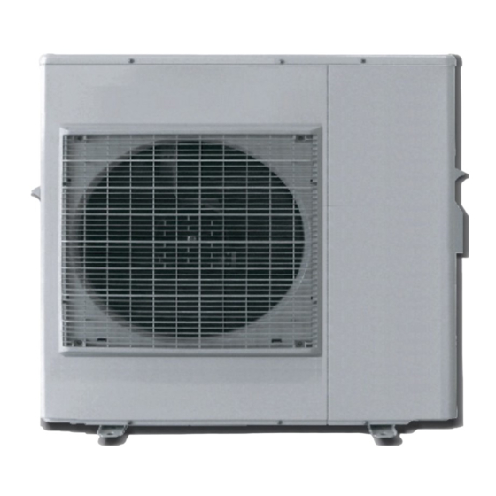
AIR TO WATER HEAT PUMP
MONOBLOC TYPE
AEYC-7134SVFU-CH1
AEYC-7134SVFU-CH2
SPECIFICATION ................................................................................................................................. 1
FUNCTIONS ....................................................................................................................................... 2
OPERATION DETAILS ...................................................................................................................... 3
TROUBLESHOOTING GUIDE ......................................................................................................... 4
ELECTRIC CIRCUIT DIAGRAM ..................................................................................................... 12
EXPLODED VIEW ............................................................................................................................ 13
PARTS LIST ....................................................................................................................................... 14
CHOFU
CONTENTS
Advertisement

Summary of Contents for CHOFU AEYC-7134SVFU-CH1
-
Page 1: Table Of Contents
CHOFU SERVICE MANUAL AIR TO WATER HEAT PUMP MONOBLOC TYPE AEYC-7134SVFU-CH1 AEYC-7134SVFU-CH2 CONTENTS SPECIFICATION ..........................1 FUNCTIONS ............................2 OPERATION DETAILS ........................3 TROUBLESHOOTING GUIDE ......................4 ELECTRIC CIRCUIT DIAGRAM ..................... 12 EXPLODED VIEW ..........................13 PARTS LIST ............................14... -
Page 2: Specification
SPECIFICATION AEYC-7134SVFU-CH2 Unit AEYC-7134SVFU-CH1 Cooling Capacity 10.0 Heating Capacity Single phase Power source TOP VIEW OUTLET Airflow Method INTAKE Cooling 2060 Input Heating 2300 Electrical Data Cooling 9.2(14.5) Running Current (MAX.) Heating 10.2(26.7) R1(25A) Water Pipe Size R1(25A) Return Power Cord Number of core-wire core-wire / 3.5~4.0mm... -
Page 3: Functions
FUNCTIONS UNIT REMOTE CONTROLLER MODE TIMER ON / OFF ON / OFF Operation mode ON/OFF Cold water mode. Mode selection Hot water mode. Timer 1 “ON” time Inverter control Timer 1 “OFF” time Inverter control reduce the ON/OFF times of Timer 2 “ON” time compressor, so can keep the water tempera- Timer 2 “OFF”... -
Page 4: Operation Details
OPERATION DETAILS DEFROSTING OPERATION(FOR UNIT HEAT EXCHANGER) • Defrosting operation is controlled by the temperature of outdoor heat exchanger sensed by the thermistor and the timer switch. • Defrosting operation starts when the both of the following conditions are met at the same time. a)35 minutes’... -
Page 5: Troubleshooting Guide
TROUBLESHOOTING GUIDE FOR YOUR SAFETY USE • For the safety and proper use and handling of the product, please read and follow the instructions carefully. • The meaning of the marks below are as follows. Danger Improper use will cause the significant risk of death or serious injury of the user. Warning Improper use may cause the risk of death or serious injury of the user. - Page 6 TROUBLESHOOTING GUIDE ERROR CODES The error codes displayed on the unit display board indicate the location of the breakdown or abnormality. UNIT APPEARANCE, PORTION, PARTS SEEMED WRONG METHOD OF CHECK ERROR CODES POWER SUPPLY check the power supply FUSE CF3 (250V T5A) check the electric continuity by tester [see fig.
- Page 7 TROUBLESHOOTING GUIDE ERROR CODES UNIT APPEARANCE, PORTION, PARTS SEEMED WRONG METHOD OF CHECK ERROR CODES SENSOR, TEMP. OUTGOING CIRCULATING accident of SENSOR check the resistance by tester [see table 1] WATER SENSOR, TEMP. RETURN CIRCULATING accident of SENSOR check the resistance by tester [see table 1] WATER turn off the power supply, wait for about 3 minutes and then power up again (*2)
- Page 8 TROUBLESHOOTING GUIDE ELECTRIC CHARACTER [table 1] Sensor, temp. defrost [table 2] Sensor, temp. discharge Sensor, temp. outdoor Temp.(°C) Resistance(kΩ) Sensor, temp. suction Sensor, temp. outgoing 1,000 and return circulating water Temp.(°C) Resistance(kΩ) DISPLAY OF ERRORS IN THE PAST 1. Display method For a unit display board •...
- Page 9 TROUBLESHOOTING GUIDE CHECK FOLLOWING STEPS [fig. 1] Continuity of current fuse on the PCB (CONTROL- [fig. 2] Voltage of fan motor on the PCB(CONTROLLER) LER) (CONTROLLER) FUSE CF4 (250V T3.15A) + + + 0Ω FUSE CF3 FAN MOTOR (250V T5A) BL Y W B R Measure voltage between the connector pins of con- 0Ω...
- Page 10 TROUBLESHOOTING GUIDE CHECK FOLLOWING STEPS [fig. 5] Resistance of OVERHEAT PROTECTOR [fig. 6] Resistance of THERMAL FUSE OVER HEAT PROTECTOR 1 or 2 THERMAL FUSE 1 or 2(133°C) 84°C OFF, 70°C ON THERMAL FUSE 1 is red wire. THERMAL FUSE 2 is white wire. OVER HEAT PROTECTOR 1 is red wire.
- Page 11 TROUBLESHOOTING GUIDE WIRING DIAGRAM AEYC-7134SVFU-CH1 AEYC-7134SVFU-CH2 – 10 –...
- Page 12 TROUBLESHOOTING GUIDE MONITOR DISPLAY METHOD Switch “ ON ” the MODE SW. 4 on the unit PCB (DISPLAY). The monitor number and monitor data are alternately displayed. Push the PUMP SW. of the unit PCB (DISPLAY). Every time the PUMP SW. is pressed the display changes in the sequence below. Switch “...
-
Page 13: Electric Circuit Diagram
ELECTRIC CIRCUIT DIAGRAM AEYC-7134SVFU-CH1 AEYC-7134SVFU-CH2 – 12 –... -
Page 14: Exploded View
EXPLODED VIEW AEYC-7134SVFU-CH1 AEYC-7134SVFU-CH2 – 13 –... -
Page 15: Parts List
PARTS LIST AEYC-7134SVFU-CH1 AEYC-7134SVFU-CH2 PARTS NAME PARTS No. OUTLET GRILLE 3011252 0 FRONT PANEL ASSY.(LEFT) 2060035 1 FRONT PANEL ASSY.(RIGHT) 2060038 0 TOP PANEL ASSY. 2060040 2 PROPELLER FAN 5263019 0 MOTOR 3011258 0 BRACKET,MOTOR 2060528 0 SENSOR (TEMP.OUTDOOR) 3011436 0 BACK PANEL ASSY. - Page 16 PARTS LIST AEYC-7134SVFU-CH1 AEYC-7134SVFU-CH2 PARTS NAME PARTS No. TANK HEATER 3011437 0 RELIEF VALVE 3011267 0 AIR PURGE VALVE 3011268 0 PRESSURE GAUGE 3011269 0 4-WAY VALVE 3010409 0 PACKING B 3011303 0 PACKING C 3011306 0 O RING (P4)
- Page 17 RA-69-[1] ISSUED DEC.2009 Printed in Japan...

Need help?
Do you have a question about the AEYC-7134SVFU-CH1 and is the answer not in the manual?
Questions and answers