
Related Manuals for CHOFU AEYC-1639U-CH

Summary of Contents for CHOFU AEYC-1639U-CH
- Page 1 AIR TO WATER HEAT PUMP HEATING AND COOLING MONOBLOC TYPE DC INVERTER INSTALLATION AND INSTRUCTION MANUAL KEEP THIS MANUAL FOR FUTURE REFERENCE AEYC-0639U-CH AEYC-1039U-CH AEYC-1639U-CH MADE IN JAPAN...
-
Page 2: Table Of Contents
Index ..1. Responsibility and recommendations 7.5 Input/Output contact ........... 7.5.1 Heating/Cooling mode remote contact 2. Specifications 7.5.2 ON/OFF DHW production remote contact ..........3. Installation 7.5.3 ON/OFF remote contact 7.5.4 EHS Alarm 3.1 Notice for safety installation 7.5.5 Flow switch 3.2 Positioning and securing 7.5.6 Dual set point control 3.3 Main components... - Page 3 1. Responsibility and recommendations General Information • Carefully read this manual and keep it for future reference. • Carefully evaluate the potential risks before carrying out any repair or maintenance, and take the necessary precautions to guarantee personal safety. • Do not attempt to repair, move or re-install the unit without the help of a qualified technician.
- Page 4 1. Responsibility and recommendations Safety procedures Important information on safety is reported on the product and contained in this Manual. Carefully read this installation manual before installing the unit. Important information for correct installation is contained in the Manual. MEANING OF THE SYMBOLS Indicates Indicates Indicates...
- Page 5 1. Responsibility and recommendations MODE MODE TIMER Strict ON / OFF ON / OFF Enforcement TIMER Strict ON / OFF ON / OFF Enforcement MODE When an anomaly is detected, as This unit must not be used by Prohibition Strict TIMER ON / OFF ON / OFF...
- Page 6 1. Responsibility and recommendations CAUTION CAUTION MODE MODE Do not extend power supply cable Do not try to repair or Prohibition TIMER Strict TIMER Strict ON / OFF ON / OFF ON / OFF ON / OFF reconstruct by yourself. or connect incorrectly.
- Page 7 1. Responsibility and recommendations Prohibition CAUTION Prohibition If the same part of the body is exposed to the floor heating for a long time, it could cause low Prohibition PROHIBITION temperature scalding. Prohibition Check personnel wears suitable personal protective equipment. Verify the absence of damages caused by transport or movement of the equipment and, immediately forward the claim to the supplier.
-
Page 8: Outdoor Temperature
1. 2. Specifications Model AEYC-0639U-CH AEYC-1039U-CH AEYC-1639U-CH Heating and Cooling Monobloc Type Type DC Inverter (Reverse cycle) Power 1N ~ 230V 50Hz Heating (*) Capacity [kW] 10.0 16.0 Power Input [kW] 1.46 2.30 3.90 Running Current (MAX.) 6.4(11.2) 10.2(17.5) 17.0(25.3) 4.11... -
Page 9: Notice For Safety Installation
3. Installation 3.1 Notice for safety installation CAUTION • Please ask qualified installer to install this unit. • Do not attempt to install this unit by yourself to avoid accidents such as electric shock, fire and leakage of water. • Before installing this unit, please read this notice for safety installation carefully and install properly and safely. •... -
Page 10: Positioning And Securing
15.3 return port R3/4(20A) 122.5 122.5 Circulating water outgoing port AEYC-1039U-CH AEYC-1039U-CH 75 70 Circulating water outgoing port R1(25A) R1(25A) Circulating water return port AEYC-1639U-CH AEYC-1639U-CH Circulating water outgoing port 1000 R1 1/4(32A) R1 1/4(32A) Circulating water return port (Unit:mm) - Page 11 3. Installation SELECTION ON THE PLACE • Consider a place where the noise and the air discharged to not affect neighbours. • Consider a position protected from the wind. • Consider an area that respects the minimum spaces recommended. • Consider a place that does not obstruct the access to doors or corridors. •...
-
Page 12: Main Components
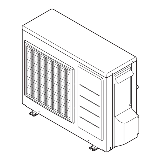
PCB(Terminal) PCB(Main) Terminal block Wiring lid Pressure relief valve Compressor Screw Pump Air outlet AEYC-1639U-CH Air inlet is located in the left or in the back PCB (Main) PCB (Terminal) Wiring lid Terminal block Pressure relief valve Airpurge valve Screw... -
Page 13: Pressures And Quantity Available At Heat Pump Outlet
3. Installation 3.4 Pressures and quantity available at heat pump outlet Main water pump in the unit has 3 levels of speed. Factory default value is level 3. Select dip switch 5 and 6 of DIP SW. on PCB(Terminal) to change the setting. AEYC-0639U Level3 Level2... -
Page 14: Water Circuit Connection
3. Installation 3.5 Water circuit connection Outlet Inlet Space Heating HP unit DHW tank Mani fold Buffer tank Shut-off valve DHW 3way valve Vibration damper joint DHW tank temperature probe Radiant panel Air bleed valve DHW Electric heater Fill/drain valve EHS* Water line filter Buffer tank temperature probe... -
Page 15: Hydraulic Connections
3. Installation Hydraulic connections The hydraulic connections of heat pump 01, must be carried out using all necessary components and completed with materials able to guarantee water seal of the threaded joints. The diagram typical of hydraulic circuit shows applications in the air conditioning field. The hydraulic circuit must be completed following the recommendations below: 1. -
Page 16: Charging Water
3. Installation Connection to the water circuit • Water connections must be made in accordance with diagram in the manual and on the unit, respecting the water in-and outlet. CAUTION • Be careful not to deform the unit piping by using excessive force when connecting. Deformation of the piping can cause the unit to malfunction. - Page 17 3. Installation NOTICE • During filling, it might not be possible to remove all air in the system. Remaining air will be removed through the automatic air purge valves during first operating hours of the system. Additional filling with water afterwards might be required.
-
Page 18: Electrical Connections
3. Installation Attachment of drain elbow • In case of using the drain elbow, attach it as illustrated. • Do not attach the drain elbow in cold districts where the air temperature falls below zero continuously. Frozen drain ice may cause obstruction to the fan. Hose Drain elbow 3.6 Electrical connections... - Page 19 3. Installation CAUTION • The unit complies with Voltage Fluctuations and Flicker (EN61000-3-11). • The unit complies with Harmonic Current Emission (EN61000-3-12). • The maximum permissible system impedance (Zmax) of the unit is 0.354 Ω(AEYC-1039U), 0.320 Ω(AEYC- 1639U). The unit must be connected to a public supply of system impedance 0.354 Ω(AEYC-1039U), 0.320 Ω (AEYC-1639U).
- Page 20 3. Installation Be sure to use an exclusive power source with a circuit breaker. Respecting the following designation, use cables whose wires size are more than the designated one in the table below. Power cord and circuit breaker shall be approved according to EN standard. Supply cord must be approved in compliance with IEC60245 IEC57 (H05RN-F).
- Page 21 3. Installation WARNING • Before starting work, check that power is not being supplied to the controller and outdoor unit. • Match the terminal board numbers and connection cord colors with those of the outdoor unit. Erroneous wiring may cause burning of the electric parts. •...
-
Page 22: Remote Controller
3. Installation 3.7 Remote controller • The connection between the equipment and the Remote controller is low-voltage circuit work, so it does not require electrician qualifications, but do follow technical standards for electrical equipment in making this installation. • Isolate the main power supply for the unit before connecting the Remote controller cord. Notes for the Remote controller installation •... - Page 23 3. Installation When the wiring is exposed Fix the mounting plate to the solid position of the wall with the attached tapping screws (L35, 2 screws). • If you tighten the screws too strongly, this can deform or break the screw hole of the mounting plate. Mounting plate Pilot hole diameter...
- Page 24 3. Installation 2. Connecting with the equipment 1. Isolate the mains power supply for the unit from the power source. Do not connect the Remote controller cord with the power on. 2. Remove the wiring lid. 3. Connect the Remote controller cord to the PCB(Terminal), No.1-2 (Remote Controller). It does not matter which wire of the Remote controller cord is connected to + and which to -.
-
Page 25: Buttons
3. Installation 3. Master and Slave setting 2 Remote controllers can be connected by 1 Master Remote controller (for Zone1) and 1 Slave Remote controller (for Zone2). Switch the Dip switch button on the back side. DIP SW SW1=OFF Master for Zone1 SW1=ON Slave... - Page 26 4. Remote Controller 4.1 Buttons Door open No. Button name Description ON/OFF Push the button for 3 seconds to turn ON and turn OFF the HP unit. Turn on the LED(green) of ON/OFF button if the HP unit is ON. The LED(red) of the ON/OFF button blinks when an alarm on the heat pump occurs.
-
Page 27: Display Panel
4. Remote Controller 4.2 Display panel • Backlight display Turn ON : Door of Remote controller open. Turn OFF: Door of Remote controller closed. Even if the door is still open, no operation of buttons for 60 seconds. No. Icons Description Power is ON, but ON/OFF switch is OFF (the unit is stopped) Indicate ON/OFF on Comfort/Economy schedule of time band setting by Circle graph... -
Page 28: Operation And Functions
5. Operation and functions of the Remote controller 5.1 System ON/OFF Press ON/OFF switch for 3 seconds to turn 3 seconds ON/OFF the system. LED (green) of ON/OFF switch is lit when the system is ON. System OFF→ON The unit starts in the operation mode with the condition at the point of the last OFF of the system. -
Page 29: Setting The Day And Time
5. Operation and functions of the Remote controller 5.2 Setting the day and time Press the Set button for 3 seconds. The day ‘Mon’ indicator will blink. (*) Select the day by pressing button, and press Set button to save the setting. The display of the day of the week changes blinking to lighted. - Page 30 5. Operation and functions of the Remote controller Note: The accuracy of the clock is ±30 second/month. If the main power turns OFF due to a power failure, etc., the time function is maintained for approximately 24 hours. Therefore, the time and day of the week settings are not required when the power turns ON again. If a power failure continues over 24 hours, the time and day of the week setting must be specified again.
-
Page 31: Selecting The Operating Mode
5. Operation and functions of the Remote controller 5.3 Selecting the operating mode Press the Mode (Heating/Cooling) button to select Heating/Cooling mode. - Heating/Cooling time band disable : Heating/Cooling OFF→Heating→Cooling Heating/Cooling OFF Heating Cooling -Heating/Cooling time band active : Heating Cooling Heating Cooling... - Page 32 5. Operation and functions of the Remote controller Press the Up or Down button to set the desired room set temperature. The temperature is adjusted by 0.5ºC. Even when Clock/Set point display of the Remote controller has been set to Clock, pressing the Up or Down button changes it to Set point display;...
-
Page 33: Domestic Hot Water Production
5. Operation and functions of the Remote controller 5.4 Domestic Hot Water production Press the DHW button to enable DHW production and change DHW mode OFF→Comfort→Economy DHW OFF 3 seconds Comfort Economy Press the DHW button for 3 seconds to enable DHW Force mode. -
Page 34: Setting The Time Bands For Heating/Cooling
5. Operation and functions of the Remote controller 5.5 Setting the time bands for Heating/Cooling Activating or deactivating the time bands Push the Timer for Heating/Cooling button once to activate the time bands, once again to deactivate. If the time bands is enabled, “On” icon is displayed. - Page 35 5. Operation and functions of the Remote controller Settings related to time band operation Press the Timer for Heating/Cooling button for 3 seconds to set the time bands for Heating/ Cooling. 3 seconds The number indicating the Zone blinks (Default: 1). Specify Zone1 or 2 using the button and then press the Set button to save the setting.
- Page 36 5. Operation and functions of the Remote controller When the day of the week has been saved, the time band operation ON/OFF (Default: off) blinks. Specify either “on” or “off” using the button and then press the Set button to save the setting.
- Page 37 5. Operation and functions of the Remote controller When the time band operation On/Off has been saved, Room set point for Heating/ Cooling (Default: 20.0°C) blinks, Change the Comfort set point temperature using the button, and press the Set button to save the setting.
- Page 38 5. Operation and functions of the Remote controller When the 1st ON time has been saved, “1 On” changes to “1 Off”. Set the 1st time band OFF time. After entering the “OFF time”, the gauge of the circle graph for ON time will be lighted, and then press the Set button to save the setting.
- Page 39 5. Operation and functions of the Remote controller Note2: After 24:00, when the operation continues into the next day, set it to OFF at 24:00 on that day and then set it to ON at 0:00 in the next day. The time bands for both Zone1 and Zone2 can be set using the Master Remote controller.
-
Page 40: Setting The Time Bands For Dhw, Low Tariff And Night Mode
5. Operation and functions of the Remote controller 5.6 Setting the time bands for DHW, Low tariff and Night mode Press the “Timer for DHW” button for 3 seconds to set the time bands for DHW. 3 seconds The icon of DHW Comfort/Low tariff/Night mode will blink, select the mode by pressing button, and press Set button to confirm the setting mode. - Page 41 5. Operation and functions of the Remote controller When the DHW Comfort icon displays and DHW Comfort set point (Default: 50°C) blinks, change the DHW Comfort set point using the button, and press Set button to save the setting. Then the DHW Economy icon displays and DHW Economy set point (Default: 40°C) blinks, change the DHW Economy set point using the...
- Page 42 5. Operation and functions of the Remote controller When DHW Comfort/Economy set point has been saved (in Low tariff or Night mode, when the mode selection has been saved), “1 On” displays and “0:00” blinks; set the 1st ON time. When the button is pressed, the time changes in 15 minute increments.
- Page 43 5. Operation and functions of the Remote controller When the setting of the 3rd time band OFF time has been specified, the relevant mode setting is complete. Return to step 2 for mode selection. Specify the setting for each mode according to the same procedures as in steps 3 to 8.
- Page 44 5. Operation and functions of the Remote controller DHW set temperature 50°C 40°C DHW time band Comfort 50°C Economy 40°C ON OFF Low tariff time band 50°C Night mode time band 0:00 3:00 6:00 9:00 12:00 15:00 18:00 21:00 24:00 Parameter Parameter Display &...
-
Page 45: Procedure For Accessing The Parameter Setting Menu
5. Operation and functions of the Remote controller 5.7 Procedure for accessing the Parameter setting menu USER level Press the Menu buttons for 3 seconds. Parameter number “0000” and parameter 3 seconds value “- - - -” will be displayed in the display. Among 4 digits of parameter numbers, 2 digits of them which indicates group or code numbers will be flashed. - Page 46 5. Operation and functions of the Remote controller Select the group and code numbers by pressing the Up or Down button, and press Set button to display the parameter value in the display. If invalid parameters (the value which is not on the parameter list or not accessible due to INSTALLER level) are entered and Set button is pressed, the indication “- - - - ”...
- Page 47 5. Operation and functions of the Remote controller When it is possible to change the parameter setting items, the displayed current parameter value will blink. Change the number in the same manner as in step 3. When the Set button is pressed, the 3 seconds number is saved and updated accordingly.
- Page 48 5. Operation and functions of the Remote controller INSTALLER level Press the Menu, , and buttons simultaneously for 3 seconds. “InSt” and parameter number “0000” and 3 seconds parameter value “- - - -” will be displayed in the 1 ・ 4 display.
-
Page 49: Pcb(Terminal
6. Electrical connections 6.1 PCB (Terminal) Reset Pump Humidity Sensor Remote Controller DHW Remote Contact ON/OFF 24VAC 3-way EHS Alarm mixing Dual Set valve Control Point Control Heating T.probe Cooling mode OUTDOOR Flow T.probe switch BUFFER T.probe Night mode Mix water T.probe tariff RS485... -
Page 50: Pcb(Terminal) Input/Output
6. Electrical connections 6.2 PCB(Terminal) Input/Output Serial connections Terminal Function Analogue Input Digital Input 1 - 2 - 3 Remote Controller 1=S1, 2=S2, 3=GND Wire length is maximum 100m with shielded cables. 15 - 16 - 32 RS485 Mod Bus , 16= , 32=GND Analogue/Digital INPUTS... -
Page 51: Parameters Input/Output
6. Electrical connections 6.3 Parameters Input/Output Parameter Display & Input value Level Function description Remarks Group Code Default min. Max. Unit T erminal 1-2-3 : Remote Controller 0=disable 1=enable T erminal 4-5-6 : 3way mixing valve 0=disable 1=enable T erminal 7-8 : DHW tank temperature probe 0=disable 1=enable Terminal 9-10 : Outdoor air temperature probe... - Page 52 6. Electrical connections Parameter Display & Input value Level Function description Remarks Group Code Default min. Max. Unit T erminal 45 : Dehumidifier 0=disable 1=enable Terminal 46 : DHW Electric heater or Backup h eater 0=DHW Electric heater 1=Backup heater T erminal 47 : Alarm (Configurable output) 0=disable 1=Alarm...
-
Page 53: Operating Modes
7. Unit Management 7.1 Operating modes The Heating and Cooling operating modes can be set, either from the Remote controller or remote contact. 7.1.1 Select mode from user interface The modes of function (Heating/Cooling) are selected pushing the dedicated Mode button. Mode button 7.1.2 Select mode by remote contact If remote Heating/Cooling changeover is enabled (dedicated parameter), the operating mode cannot be changed... -
Page 54: Water Temperature Set Point
7. Unit Management 7.2 Water temperature set point The water temperature set point can be selected with “traditional” mode, i.e. based on a fixed set point programmed by the user, or in “advanced” mode, with a variable set point calculated automatically using climatic curves, both in Heating and Cooling mode, as described below. -
Page 55: Heating Climatic Curves
7. Unit Management 7.2.2 Climatic curve The Outgoing water temperature set point in Heating or Cooling mode is calculated based on the Outdoor air temperature trend according to selectable curves. 7.2.2.1 Heating Climatic curves The logic regulating the temperature of the requested outlet water to the HP unit, in normal winter Heating or summer Cooling operation, is based on the Climatic curves. -
Page 56: Cooling Climatic Curves
7. Unit Management 7.2.2.2 Cooling Climatic curves The compensation curves in Cooling mode can be modified to allow correct HP unit operation depending on the Cooling system used (radiant panels, fan coils). Outgoing water set point Tm1(20.0°C) Tm2(18.0°C) Outdoor air temperature Te1(25.0°C) Te2(35.0°C) (Selected by Par5109) -
Page 57: Additional Outdoor Air Temperature Probe For Climatic
7. Unit Management 7.2.3 Additional Outdoor air temperature probe for Climatic curves If the positioning of the HP unit is non-representative to measure the Outdoor air temperature for a correct calculation of the water set point by Climatic curve, an additional temperature probe can be provided. Additional probe Outdoor air temperature PCB(Terminal) - Page 58 7. Unit Management 7.2.4 Buffer tank temperature probe If using the Buffer tank temperature probe and it is enabled, the compressor and water pump turns ON/OFF based on water temperature measured by the Buffer tank temperature probe. The functions of “Backup heater” and the “External heat source (EHS)”...
-
Page 59: Hp Unit Control
7. Unit Management 7.2.5 HP unit control T he HP unit control based on: 1) Outgoing water temperature (measured by Outgoing water sensor on HP unit) 2) Outgoing water temperature and Room air temperature (measured by sensor on board of the Remote controller) 3) Buffer tank temperature (measured by Buffer tank sensor) 4) Buffer tank temperature and Room air temperature 5) DHW tank temperature (measured by DHW tank sensor) -
Page 60: Hp Unit Controlled Based On Outgoing Water Temperature
7. Unit Management 7.2.5.1 HP unit controlled based on Outgoing water temperature Based on the Outgoing water temperature setting, the compressor is controlled and turned ON/OFF. Start of operation When the Outgoing water temperature does not reach the water set point, HP unit is turned ON. Heating : Outgoing water temp. -
Page 61: Hp Unit Controlled Based On Buffer Tank Temperature
7. Unit Management 7.2.5.3 HP unit controlled based on Buffer tank temperature In order to reach the Buffer tank set point, compressor frequency shall be controlled so that Outgoing water temperature can reach the maximum temperature in Heating mode (60°C) or minimum temperature in Cooling mode (7°C). - Page 62 7. Unit Management 7.2.5.4 HP unit controlled based on Buffer tank temperature and Room air temperature In order to reach the Buffer tank set point, compressor frequency shall be controlled so that Outgoing water temperature can reach the maximum temperature in Heating mode (60°C) or minimum temperature in Cooling mode (7°C).
-
Page 63: Compressor Control
7. Unit Management 7.2.5.5 HP unit controlled based on DHW tank temperature DHW tank set point can be selected from Comfort, Economy, or Force. In order to reach the DHW tank set point, compressor frequency shall be controlled so that Outgoing water temperature can reach the maximum temperature in Heating mode (60°C). -
Page 64: Heating Mode
7. Unit Management Based on water temperature Heating mode Heat pump Maximum Compressor (Hz) minimum set temp. + 1 Water set temp. (°C) set temp. - 1 set temp. - Hysteresis Comp. OFF Comp. OFF → ON Water temperature is stable Heating ON set point + 1°C ×... -
Page 65: Water Pump Management
7. Unit Management 7.3 Water pump management 7.3.1 Main water pump Fundamentally, ON/OFF of the Main water pump links to ON/OFF of the compressor, but the setting ON/OFF of the pump during compressor OFF states, due to reaching the Room set point shall be set in the following parameters;... -
Page 66: Unlock Pump Function
7. Unit Management Compressor ON (5sec) Water temp. detect Main water pump ON (3min) (5min) (3min) Delay time Time OFF Time ON Parameters Parameter Display & Input value Level Function description Remarks Group Code Default min. Max. Unit T ype of configuration of Main water pump 0=always ON 1=ON/OFF based on Buffer tank temperature To be set to... -
Page 67: Pump Output Adjustment Function
7. Unit Management 7.3.1.4 Pump output adjustment function If an excessive flow rate occurs due to low pressure loss of the circulating loop, adjust the Main water pump output so that the flow rate is reduced. Using the Dip switch on the PCB(Terminal), 3-level setting is possible. Be aware that an excessively low flow rate may cause problems including diminished capacity, poor circulation, unavailable flow switch control, and freezing of the water heat exchanger. -
Page 68: Frost Protection
7. Unit Management 7.4 Frost protection Frost protection can be activated when the HP unit is in OFF mode. This is controlled based on either the Outgoing water or air temperature: Frost protection based on Room air temperature Frost protection based on Outdoor air temperature Frost protection based on Outgoing water temperature DHW tank frost protection Secondary system circuit frost protection... - Page 69 7. Unit Management 7.4.2 Frost protection based on Outdoor air temperature The Frost protection function is always active, even when the heat pump is OFF. The water pump is activated if the Outdoor air temperature measure by the HP unit built-in Outdoor temperature sensor is less than the start temperature and deactivated when the Outdoor air temperature rises back “Outdoor air temperature set point + Hysteresis”.
- Page 70 7. Unit Management 7.4.3 Frost protection based on Outgoing water temperature The frost protection function is always active, even when the heat pump is OFF. The water pump is activated if the Outgoing water temperature is less than the start temperature and deactivated when the Outgoing water temperature rises back “Outgoing water temperature set point + Hysteresis”...
- Page 71 7. Unit Management 7.4.4 DHW tank frost protection The purpose of this function, is to protect the DHW tank against the formation of ice, activating the Electric heater according to the function described in the following graph. This function is carried out only by the DHW Electric heater, therefore this needs to be configured by Par5146=0. DHW Electric heater hysteresis (3.0°C)
-
Page 72: Input/Output Contact
7. Unit Management 7.5 Input/Output contact 7.5.1 Heating/Cooling mode remote contact Heating/Cooling operating mode can be managed from a remote contact. If remote Heating/Cooling changeover is enabled by Par5124, the operating mode cannot be changed by the Remote controller. Heating/Cooling remote contact PCB(Terminal) Contact OPEN = Heating Contact CLOSE = Cooling... -
Page 73: On/Off Dhw Production Remote Contact
7. Unit Management 7.5.2 ON/OFF DHW production remote contact The enabling of the DHW production can be managed from remote contact. If the remote ON/OFF DHW changeover is enabled by Par5119, the DHW mode cannot be changed by the Remote controller. - Page 74 7. Unit Management Priority of DHW production mode The top priority is “by time band”, the second priority is “by remote contact”, then “by button of Remote controller”. If DHW production is operated by using the remote, the setting temperature shall be “Comfort”. DHW mode states DHW mode states based on priority Turn ON/OFF DHW...
-
Page 75: Ehs Alarm
7. Unit Management 7.5.3 ON/OFF remote contact HP unit can be turned ON/OFF by remote contact with timer or thermostat in the room. In case the Remote controller is not connected, HP unit will be turned ON/OFF according to remote contact. In case the Remote controller is connected, if both Remote controller and remote contact are not ON, HP unit will not be turned ON. - Page 76 7. Unit Management Note1: When both the DHW production and ON/OFF remote contact are simultaneously ON, DHW operation has priority. DHW has priority than Heating/Cooling ON/OFF contact contact HP unit Heating Heating HP unit states Note2: In case the ON/OFF remote contact is enabled and Heating/Cooling remote contact is disabled (by Remote controller), if the ON/OFF remote contact=ON and Heating or Cooling is in operation, and if the Mode button of Remote controller is used to select OFF among Heating→Cooling→OFF, the ON/OFF remote contact=ON condition will be top priority than the Mode button of Remote controller.
- Page 77 7. Unit Management 7.5.4 EHS Alarm In case of the hybrid solution, gas boiler + HP unit, the EHS Alarm digital input of the HP unit receives a signal from the boiler in fault, and the HP unit is forced in Heating to heat the water for space Heating or for DHW according the priority setting.
-
Page 78: Flow Switch
7. Unit Management 7.5.5 Flow switch The flow switch is connected at the terminal on the PCB. When the compressor and pump operate, the adjusted flow rate is reached, the flow switch contact closes, The intent is to protect the plate-to-plate heat exchanger in Cooling mode. -
Page 79: Dual Set Point Control
7. Unit Management 7.5.6 Dual set point control Applies only to installations with different heat emitters which require different set points (e.g. fan coil and floor heating). Dual set point control makes it possible to generate two different set points. The selection between the two set points is available by the remote contact. -
Page 80: Additional Water Pump
7. Unit Management 7.5.7 Additional water pump A parameter can be used to set the desired operation: - Additional water pump1 - Additional water pump2 Parameters Parameter Display & Input value Level Function description Remarks Group Code Default min. Max. Unit T erminal 48 : Pump1 0=disable... - Page 81 7. Unit Management Scheme <A> set configuration Depending on Main water pump setting Depending on Main water pump setting but always OFF when the DHW mode is activated DHW tank HP unit Space Heating 3way valve Pump 1 Scheme <B> set configuration Depending on Main water pump setting Depending on Main water pump setting but always OFF when the DHW mode is activated Always ON, apart from if any alarms are active or if the HP unit is in OFF mode...
- Page 82 7. Unit Management 7.5.7.2 Additional water pump2 A parameter can be used to set the desired type of pump operation, as follows: Depending on Main water pump setting Depending on Main water pump setting but always OFF when the DHW mode is activated Always ON, apart from if any alarms are active or if the HP unit is in OFF mode ON/OFF based on Room air temperature (set by Remote controller) Note: As for above sentence No.
- Page 83 7. Unit Management Scheme <A> set configuration Depending on Main water pump setting Depending on Main water pump setting but always OFF when the DHW mode is activated DHW tank HP unit Space Heating 3way valve Space Heating Pump1 Pump2 Scheme <B>...
-
Page 84: Heating/Cooling Mode Output
7. Unit Management 7.5.8 Heating/Cooling mode output The purpose of this output is to communicate signals to an external controller so that the operation mode is displayed in the controller and that the 3way valve can be controlled using the controller. When space heating is provided through the floor Heating + fan coil units and Cooling is provided with the fan coil units only;... -
Page 85: Configurable Contact (Alarm
7. Unit Management 7.5.9 Configurable contact (Alarm) This parameter can be used to set the desired operation, as follows: Alarm Ambient temperature reached Parameters Parameter Display & Input value Level Function description Remarks Group Code Default min. Max. Unit T erminal 47 : Alarm (Configurable output) 0=disable 1=Alarm 2=Ambient temperature reached... - Page 86 7. Unit Management 7.5.9.2 Ambient temperature reached The intent of this output is to give a signal to a potential Fan coil system when the Room air temperature, measured by the Remote controller, is reached, so that the Fan coils will stop. When the Fan coil system is restarted by the predetermined Room air temperature hysteresis, transmission of the signal is halted.
-
Page 87: Night Mode
7. Unit Management 7.5.10 Night mode If there is a need to reduce the maximum value of electric and/or noise absorption of the compressor, e.g. in night-time operation, it is possible to activate the Night mode function using the relative external contact (Terminal 28-29) or Low tariff/Night mode button of the Remote controller. - Page 88 7. Unit Management 7.5.11 Low tariff The purpose of this function, enabled by the digital input (Terminal 30-31) or Low tariff/Night button of the Remote controller, is to force the charge of all buffers in the system and DHW tank and buffer according the specified priorities during times when electricity rates are inexpensive.
-
Page 89: Dehumidifier Management
7. Unit Management 7.5.12 Dehumidifier management To adjust ambient humidity, a dehumidifier can be used. Dehumidifier control is possible only during Cooling mode. If dehumidification is required, then its possible to control the dehumidifier through a relay connected between Terminal 45-N. The dehumidifier managed with humidity sensor. - Page 90 7. Unit Management The Humidity Sensor connected in the Terminal 17-18. The controller receives the relative humidity signal in the form of voltage signals (DC0~10 V). The respective room humidity is calculated via the linear characteristic which is defined by 2 fixed points (voltage value1 / function value1 and voltage value2 / function value2).
- Page 91 7. Unit Management Maximum Room humidity compensation The Outgoing water set point, calculated based on the Climatic curve, can be compensated according to the maximum relative humidity in the room to prevent and to avoid possible formation of condensate in the floor in case of floor cooling system.
-
Page 92: Space Heating Management
7. Unit Management 7.5.13 Space Heating management The System controller uses the “zone of greatest demand” strategy for calculating the Outgoing water temperature required from the HP unit (and/or EHS as Electric heater or Boiler). Zone1 DHW tank Master 3way valve Remote controller HP unit Mixing... - Page 93 7. Unit Management Outgoing water temp control by HP unit HP unit operates in order to reach the set point of Outgoing water temperature or Tank temperature (DHW tank or Buffer tank). Set point of Outgoing water temperature of Heating/Cooling can be Fixed or Climatic curve. To reach the set point of Tank temperature, the Outgoing temperature shall be set as a Maximum water temperature (60°C) in Heating or Minimum water temperature (7°C) in Cooling mode.
- Page 94 7. Unit Management 2) Zone1 and Zone2 In the case of water temp control, Par4100=0, the HP unit operates in order for S1 to reach the set point (Fixed or Climatic curve) In the case of room temp control, Par4100=1, the HP unit can be turned ON/OFF by T1, T2 and the set point of Remote controller (HP unit is turned OFF if both T1 and T2 reach the set point) As for the set point of S1 (Fixed or Climatic curve) at Zone2 ON, if Terminal 22-23 (Dual set point) is OPEN, it will be set point of Zone1.
- Page 95 7. Unit Management 3) Zone1, and DHW tank He ating/Cooling: In the case of water temp control, Par4100=0, the HP unit operates in order for S1 to reach the set point (Fixed or Climatic curve) In the case of room temp control, Par4100=1, the HP unit can be turned ON/OFF by T1 and the set point of Remote controller.
- Page 96 7. Unit Management 4) Zone1 (Pump1, Mixing valve), Zone2 (Pump2), Buffer tank, DHW tank He ating/Cooling: In the case of the Buffer tank temperature probe being enabled (Par5111=1), the HP unit operates with maximum water temperature in Heating (60°C) or minimum water temperature in Cooling (7°C) in order for S3 to reach the Buffer tank set point.
-
Page 97: Dhw 3Way Valve Management
8. Domestic Hot Water Production 8.1 DHW 3way valve management The DHW 3way valve is used in systems where DHW needs to be stored in the DHW tank. It is used switch the flow of water between the system and the DHW tank loop. The DHW tank temperature could be detected with a probe. -
Page 98: Max Time For Dhw Request
8. Domestic Hot Water Production 8.1.1 Max time for DHW request In case of a simultaneous demand, a parameter with which the priority between DHW and System is specified is available. The switching from DHW to the System after the first startup will be based on reaching of DHW set point or by Par3121 (60min), and the switching from the System to the DHW will be based on Par3122 (15min). -
Page 99: Dhw Production Mode
8. Domestic Hot Water Production 8.2 DHW production mode DH W production can be activated/deactivated by: Pressing the DHW button on the Remote controller DHW remote contact Pressing the Timer for DHW button on the Remote controller The heat pump can heat only the DHW tank when hot or cold water is not needed for space Heating/Cooling. Setting Par3101 to completely disable the DHW function to avoid the selection by the DHW button. -
Page 100: Heat Pump Only
8. Domestic Hot Water Production Th e following set points are used for temperature control Par3111: DHW Comfort set point (typically used in the daytime, when time bands have been set) Par3112: DHW Economy set point (typically used at night, when time bands have been set) Par3114: DHW Over boost set point (this value allows the DHW tank to be heated to a temperature above the set point, either Comfort or Economy) Parameters... - Page 101 8. Domestic Hot Water Production 8.2.1 Heat pump only The HP unit is activated to produce DHW, if the DHW tank temperature falls below the value set for parameter “Economy DHW set point – DHW hysteresis” or “Comfort DHW set point – DHW hysteresis”. HP unit stops DHW production: When the DHW tank temperature reached to DHW set point.
- Page 102 8. Domestic Hot Water Production Note1: Whenever HP unit stops producing DHW, it becomes available again to produce for the Heating/Cooling system. Note2: To prevent the HP unit operating in DHW mode for too long, the maximum DHW production time must be set using Par3121 (60min), after which the unit will once again be available for space Heating/Cooling.
- Page 103 8. Domestic Hot Water Production 8.2.2 DHW Electric heater only In this configuration, the DHW tank will only be heated using the DHW Electric heater. DHW hysteresis DHW Electric heater (3.0°C) DHW tank temperature DHW set point Comfort (50.0°C) Economy (40.0°C) Over boost (60.0°C)
- Page 104 8. Domestic Hot Water Production Digital Output “Electric heater” Note: Terminal46 (Electric heater) digital output can be set by Par5146, for the DHW Electric heater output, or for the Backup heater. If the digital output is “DHW Electric heater” the digital output follows the logic explained “DHW heater only”,“...
-
Page 105: Heat Pump + Dhw Heater
8. Domestic Hot Water Production 8.2.3 Heat pump + DHW heater The HP unit will operate as described in paragraph “Heat pump only”, with the following differences A) and B). A) DHW tank temperature reached set point (Comfort or Economy) The DHW heater will start with a fixed delay of 30 sec, aiming to reach the Over boost set point. -
Page 106: Legionella Prevention Function
8. Domestic Hot Water Production Conditions to be available DHW heaters “Always enabled” or “depends on Outdoor air temperature” shall be selected by Par3132. In case of “depends on Outdoor air temperature”, the Outdoor air temperature which turns ON DHW heaters shall be set by Par3133. - Page 107 8. Domestic Hot Water Production B) HP unit is out of operation range The compressor will be stopped and the DHW heater will be started, aiming to reach the Over boost set point. Over boost hysteresis DHW heater (5.0°C) DHW hysteresis Compressor (3.0°C) temperature...
- Page 108 8. Domestic Hot Water Production 8.2.4 Legionella prevention function This function is to sterilize legionella bacteria by heating and maintaining the specific temperature (65°C or higher) in DHW tank for the specific time (10min). Regarding the conditions of this function, “States (enable/disable)”, “Operation interval (day of the week)”, and “Start time (start production to anti legionella set point)”...
- Page 109 8. Domestic Hot Water Production 8.3 Backup heater The function of Backup heater is to heat DHW tank and Heating system in Replace or Supplementary mode by the HP unit when the Heating capacity of HP unit is decreased by lower Outdoor air temperature and when the HP unit is stopped due to the failure of sensors.
-
Page 110: Backup Heater In Replacement Mode
8. Domestic Hot Water Production 8.3.1 Backup heater in Replacement mode The Backup heater is activated for space Heating or DHW (in the latter case, only if no dedicated DHW tank heater is fitted) to replace the compressor, if the compressor is unable to meet demand as it has shut down for one of the fo llowing reasons: HP unit stopped (according of operating limits) Probe faults (see lists below) - Page 111 8. Domestic Hot Water Production Note1: If “Frost protection on Room air temperature” is activated, the top priority is the set point of Frost protection (Par4303=35°C) than that of Emergency mode (Par4601=50°C). Note2: The Backup heater will be available for the System during “Min. time for space Heating/Cooling” after the “Max.
- Page 112 8. Domestic Hot Water Production Must be allowed to define the Outdoor air temperature below which the space heating or DHW will be heated by Backup heater according the explanation above. Parameter to define whether the Backup heater is “always enabled”...
-
Page 113: Backup Heater In Supplementary Mode
8. Domestic Hot Water Production 8.3.2 Backup heater in Supplementary mode For space heating, once enabled, the heater will be activated according to the Water temperature, as shown in the following graph. Water temperature Integration time for starting heaters Real water temperature (600°C×sec) HP control set point hysteresis... - Page 114 8. Domestic Hot Water Production Note1: The calculation of the Integration time only begins after the time set for Par4604 (Heater activation delay time) has elapsed. The function is designed to prevent the heater from starting in Supplementary mode, to allow the HP unit time to reach steady operation.
- Page 115 8. Domestic Hot Water Production Parameters Parameter Display & Input value Level Function description Remarks Group Code Default min. Max. Unit B ackup heater type of function Par4600 and Par4700 0=disable are synchronized 1=Replacement mode Par4600=1, 2, 3 2=Emergency mode →...
-
Page 116: Freeze Protection Function
8. Domestic Hot Water Production 8.3.3 Freeze protection function The Backup heater can be enabled as “Freeze protection function” and will be operated during the Defrost or Start-up. The function of Backup heater as “Freeze protection” can be enabled or disabled by Par4620. Backup heater enabled during Start-up If the Par4620=1 (enabled during Start-up), the Backup heater will be activated after 30sec. - Page 117 8. Domestic Hot Water Production Backup heater enabled during Defrost If the Par4620=2 or 3 (enabled during Defrost), the Backup heater shall be turned ON during Defrost operation when Outgoing water temperature is lower than Par4623. Once the water temperature reaches the set point of Par4623 + hysteresis, the Backup heater shall be turned OFF.
-
Page 118: Ehs (External Heat Source
8. Domestic Hot Water Production 8.4 EHS (External heat source) The function of EHS (External heat source) is to heat the Heating system in Replace or Supplementary mode by HP unit when the heating capacity of HP unit is decreased by lower Outdoor air temperature and when HP unit is stopped due to the failure of sensors. -
Page 119: Ehs In Replacement Mode
8. Domestic Hot Water Production 8.4.1 EHS in Replacement mode The EHS is activated for Heating to replace the compressor, if the compressor is unable to meet demand as it has sh ut down for one of the following reasons: HP unit stopped (according of operating limits) Probe faults (see lists below) When probe faults occurred, The EHS is activated for;... - Page 120 8. Domestic Hot Water Production Parameters Parameter Display & Input value Level Function description Remarks Group Code Default min. Max. Unit E HS type of function Par4600 and Par4700 0=disable are synchronize 1=Replacement mode Par4600=1, 2, 3 2=Supplementary mode → Par=4700=0 Par4700=1, 2 C onditions to be available EHS →...
-
Page 121: Ehs In Supplementary Mode
8. Domestic Hot Water Production 8.4.2 EHS in Supplementary mode Once space heating is enabled, the EHS will be activated according to the water temperature as shown in the following graph. water temperature Integration time for starting EHS Real water temperature (600°C×sec) HP control set point hysteresis... - Page 122 8. Domestic Hot Water Production Note1: The calculation of the Integration time only begins after the time set for Par4706 (EHS activation delay) has elapsed. The function is designed to prevent the EHS from starting in Supplementary mode, to allow the HP unit time to reach steady operation.
- Page 123 8. Domestic Hot Water Production Parameters Parameter Display & Input value Level Function description Remarks Group Code Default min. Max. Unit E HS type of function Par4600 and Par4700 0=disable are synchronized 1=Replacement mode Par4600=1, 2, 3 2=Supplementary mode → Par=4700=0 Par4700=1, 2 C onditions to be available EHS →...
-
Page 124: Access Limitation
9. Parameters List 9.1 Access limitation There are 3 levels of access limitation for parameter settings. See “5.7 Procedure for accessing the parameter setting menu” for how to access the parameter as each procedure is different from each level. Ac cess level U=End User Level (accessible to User level only) ... - Page 125 9. Parameters List Read value of conditions and settings (Read only) Parameter Display & Input value Level Function description Remarks Group Code Default min. Max. Unit S elected operating mode Set by Remote 0=Heating/Cooling OFF controller or remote 1=Heating contact 2=Cooling Set by Master Remote Room air set temperature of Zone1(Master) 25.0 12.0 40.0 0.5°C controller...
- Page 126 9. Parameters List Remote controller Parameter Display & Input value Level Function description Remarks Group Code Default min. Max. Unit Adjust the temperature read by the sensor in Remote Master -5.0 0.1°C controller Remote controller S o und ON/OFF of buzzer 0=OFF 1=ON B ack light display at door open 0=OFF 1=ON Time to turn off the back light...
- Page 127 9. Parameters List Time bands settings of Heating/Cooling (Zone1) Parameter Display & Input value Level Function description Remarks Group Code Default min. Max. Unit T i me band is ON/OFF on Monday 0=OFF 1=ON Comfort room set temperature on Monday 20.0 12.0 40.0 0.5°C Economy room set temperature on Monday 18.0 12.0 40.0 0.5°C 1st ON time on Monday 0:00 0:00 24:00 15min 1st OFF time on Monday 0:00 0:00...
- Page 128 9. Parameters List Time bands settings of Heating/Cooling (Zone1) Parameter Display & Input value Level Function description Remarks Group Code Default min. Max. Unit T i me band is ON/OFF on Saturday 0=OFF 1=ON Comfort room set temperature on Saturday 20.0 12.0 40.0 0.5°C Economy room set temperature on Saturday 18.0 12.0 40.0...
- Page 129 9. Parameters List Time bands settings of Heating/Cooling (Zone2) Parameter Display & Input value Level Function description Remarks Group Code Default min. Max. Unit T i me band is ON/OFF on Monday 0=OFF 1=ON Comfort room set temperature on Monday 20.0 12.0 40.0 0.5°C Economy room set temperature on Monday 18.0 12.0 40.0 0.5°C 1st ON time on Monday 0:00 0:00 24:00 15min 1st OFF time on Monday 0:00 0:00...
- Page 130 9. Parameters List Time bands settings of Heating/Cooling (Zone2) Parameter Display & Input value Level Function description Remarks Group Code Default min. Max. Unit T i me band is ON/OFF on Saturday 0=OFF 1=ON Comfort room set temperature on Saturday 20.0 12.0 40.0 0.5°C Economy room set temperature on Saturday 18.0 12.0 40.0...
- Page 131 9. Parameters List Time bands settings of DHW Parameter Display & Input value Level Function description Remarks Group Code Default min. Max. Unit DHW Comfort 1st ON time 0:00 0:00 24:00 15min DHW Comfort 1st OFF time 0:00 0:00 24:00 15min DHW Comfort 2nd ON time 0:00 0:00 24:00 15min DHW Comfort 2nd OFF time 0:00 0:00 24:00 15min DHW Comfort 3rd ON time 0:00 0:00 24:00...
- Page 132 9. Parameters List Water temperature set points of Heating/Cooling Parameter Display & Input value Level Function description Remarks Group Code Default min. Max. Unit Min. Outdoor air temperature corresponding to max. 25.0 50.0 0.5°C Outgoing water temperature (Te1) Zone1 Max. Outdoor air temperature corresponding to max. 35.0 50.0 0.5°C Outgoing water temperature (Te2) Zone1 C o oling Zone2, enable Outgoing water set point 0=Fixed set point 1=Climatic Curve Enabled Cooling Zone2, Fixed Outgoing water set point in 23.0 0.5°C Cooling Max. Outgoing water temperature in Cooling mode ...
-
Page 133: Water Pump
9. Parameters List HP unit Parameter Display & Input value Level Function description Remarks Group Code Default min. Max. Unit T h e HP unit turns ON/OFF based on 0=Room set point 1=Water set point Hysteresis of Heating Room air set point 0.5°C Hysteresis of Cooling Room air set point 0.5°C Max. frequency of Night mode Min. time compressor ON – OFF time... - Page 134 9. Parameters List Frost protection Parameter Display & Input value Level Function description Remarks Group Code Default min. Max. Unit Start temperature of Frost protection on Room air 14.0 40.0 0.5°C temperature Hysteresis of Room air temperature of Frost protection 0.5°C Water temperature of Frost protection 35.0 10.0 60.0 0.5°C Delay time OFF Main water pump from OFF Frost 1sec protection operation function Start temperature of Frost protection on Outdoor air 10.0 0.5°C temperature Hysteresis of Outdoor air temperature 0.5°C Backup heater set point during Frost protection 10.0 0.5°C Hysteresis of Outgoing water temperature...
- Page 135 9. Parameters List Backup heater Parameter Display & Input value Level Function description Remarks Group Code Default min. Max. Unit B ackup heater type of function Par4600 and Par4700 0=disable are synchronized 1=Replacement mode Par4600=1, 2, 3 2=Emergency mode →Par4700=0 3=Supplementary mode Par470=1, 2 →Par4600=0 Manual water set point 50.0 40.0 60.0 0.5°C...
- Page 136 9. Parameters List Input/Output Parameter Display & Input value Level Function description Remarks Group Code Default min. Max. Unit T erminal 1-2-3 : Remote Controller 0=disable 1=enable T e rminal 4-5-6 : 3way mixing valve 0=disable 1=enable T erminal 7-8 : DHW tank temperature probe 0=disable 1=enable Terminal 9-10 : Outdoor air temperature probe (additional) 0=disable 1=enable To be set to the...
- Page 137 9. Parameters List Input/Output Parameter Display & Input value Level Function description Remarks Group Code Default min. Max. Unit T e rminal 45 : Dehumidifier 0=disable 1=enable T erminal 46 : DHW Electric heater or Backup heater 0=DHW Electric heater 1=Backup heater T e rminal 47 : Alarm (Configurable output) 0=disable 1=Alarm 2=Ambient temperature reached T erminal 48 : Pump1 0=disable...
-
Page 138: Installation Check
10. Installation check and Test operation Carefully explain the operation method to the customer using the manual. Before starting the HP unit, check each item in the list below and put a tick mark in the 10.1 Installation check Locations and positioning ... -
Page 139: Test Operation
10. Installation check and Test operation 10.2 Test operation Test operate the system according to the manual. Check if the system operates normally. The circulating water go to the stipulated flow range The temperature adjustment and timer operation possible The system is free of abnormal noises ... -
Page 140: Error Code Display
11. Service and Maintenance 11.1 Error code display In the event that an error is detected, the error code will be displayed in Remote controller and PCB (Terminal) display. As for the display in Remote controller, LED (red) on ON/OFF switch will be flashed, and warning icon and 2 or 3digits error code will be displayed on LCD screen. Error code (2digits) will be displayed on the PCB (Terminal) display. Remote controller PCB(Terminal) LED(red) Reset SW. Pump SW. warning icon and error code Display 11.2 Error history display ・ The previous 10 error codes can be displayed on PCB (Terminal) display. Procedure to display on PCB(Terminal) display ・... -
Page 141: Method Of Reset Error Code Display
11. Service and Maintenance 11.3 Method of reset error code display The procedure to reset the error display differs to error codes and there are 3 types to reset; Auto, Power OFF, and Manual. See “List of Error codes” for the procedure to reset each error code. Auto : A utomatically. Once it returns to normal condition, the error will be reset. When the unit stops, it may not possible to reset automatically. Then, it shall be reset manually. Power OFF : M anually. If HP unit returns to normal condition, turn OFF the power supply once and turn ON again, then the error will be reset. - Page 142 11. Service and Maintenance 11.4 List of Error codes HP unit alarms Error Appearance, Portion, Parts Figure/ Error Method of check Troubleshooting codes seemed wrong Table reset Power supply Check the power supply Confirm the power supply Fuse CF1 0639U : 250V 15A Check the electric continuity of If CF1 is blown, PCB (Main) should be Fig.
- Page 143 11. Service and Maintenance Error Appearance, Portion, Parts Figure/ Error Method of check Troubleshooting codes seemed wrong Table reset PCB (Main) PCB (Main) should be replaced disconnection Ensure the installation position to avoid blockage of air inlet & outlet Unreasonable Check the place of installation operation (blockage of air inlet &...
- Page 144 11. Service and Maintenance Error Appearance, Portion, Parts Figure/ Error Method of check Troubleshooting codes seemed wrong Table reset Fuse CF6 Check the electric continuity If CF6 is blown, it should be replaced (1639U : 250V T3.15A) of Fuse CF6 by tester Lower Fan Fuse CF7 Check the electric continuity If CF7 is blown, it should be replaced motor error (1039U : 250V T3.15A)
- Page 145 11. Service and Maintenance Error Appearance, Portion, Parts Figure/ Error Method of check Troubleshooting codes seemed wrong Table reset Compressor Compressor overheat If Compressor overheat protection Check the resistance by tester Fig. 8 overheat protection relay relay blown, it should be replaced protection relay Manual Check the service valve and Correct refrigerant once, then...
- Page 146 11. Service and Maintenance Error Appearance, Portion, Parts Figure/ Error Method of check Troubleshooting codes seemed wrong Table reset Room temp. Sensor,Temp.Room (Master Master Remote controller should be (Master Remote Remote replaced controller) controller) error Auto Room temp. Sensor,Temp.Room Slave Remote controller should be (Slave Remote (Slave Remote replaced...
-
Page 147: Check And Troubleshooting
11. Service and Maintenance 11.5 Check and troubleshooting Method of check Voltage, Resistance, Continuity [Fig. 1] Continuity of current Fuse on the PCB (Main) [0639U,1039U] [1639U] Fuse CF1 (250V T30A) Fuse CF3 (250V 3A) (Main) (Main) 0Ω Fuse CF4 Fuse CF1 (250V 3A) 0639U : 250V 15A 1039U : 250V 25A... - Page 148 11. Service and Maintenance [Fig. 4] Voltage of Pump on the PCB (Main) Pump (0639U,1039U) Measure voltage between the connector pins of connector Connector shall be checked during Heating or Cooling operation. Measure voltage as follows without taking off the connector Pump (1639U) Measure voltage between the connector pins of connector Connector...
- Page 149 11. Service and Maintenance [Fig. 7] Continuity of current Fuse on the PCB (Main) [0639U,1039U] [1639U] (Main) (Main) Fuse CF2 0639U : 250V T3.15A 1039U : 250V T3.15A Fuse CF2 (250V T5A) [Fig. 8] Resistance of the Compressor overheat protection relay 0Ω...
- Page 150 11. Service and Maintenance Electric character of the sensors [Table 1] Sensor, temp. Outdoor (HP unit) [Table 2] Sensor, temp. Discharge Temp.(°C) Resistance(kΩ) Temp.(°C) Resistance(kΩ) 27 8.2 3.2 [Table 3] Sensor, temp. Suction/Defrost [Table 4] Sensor, temp. Outgoing water/Return water Sensor, temp.
-
Page 151: Wiring Diagram
11. Service and Maintenance Wiring Diagram AEYC-0639U-CH AEYC-1039U-CH DIP SW. RESET SW. PUMP SW. BL Y Humidity Sensor SENSOR(TEMP., OUTDOOR) Remote Controller SENSOR(TEMP., DEFROST) DHW Remote Contact SENSOR(TEMP., DISCHARGE) ON/OFF 24VAC 3-way EHS Alarm SENSOR(TEMP., SUCTION) mixing Dual Set valve EEPROM Control Point... - Page 152 11. Service and Maintenance AEYC-1639U-CH REACTOR REACTOR RAM CLEAR DIP SW. RESET SW. PUMP SW. Humidity Sensor Remote Controller DHW Remote Contact ON/OFF COMPRESSOR 24VAC EEPROM 3-way (CONTROLLER) EHS Alarm mixing Dual Set valve Control Point upper Control Heating T.probe...
-
Page 153: Monitor Display Function
11. Service and Maintenance 11.6 Monitor display function ・ The conditions and settings of HP unit can be displayed on Remote controller or PCB (Terminal) display. Display on Remote controller 1. Press Return button for 3 seconds to enter monitor mode and display USER level value of parameter group 01. 2 digits (Code No. of parameter group 01 : default value is 00) will be displayed on the left of Remote controller screen. - Page 154 11. Service and Maintenance Monitor display Remote Display & Input value (Terminal) controller Function description Remarks Number Parameter Default min. Max. Unit Circulating water return temperature 1°C Compressor operating frequency Discharge temperature 1°C Current consumption value 9900 100W Fan control number of rotation 1000 10rpm Defrost temperature...
- Page 155 11. Service and Maintenance 11.7 Maintenance WARNING Before performing any maintenance make sure you have removed the power acting on the switch. • Check that the staff wears suitable individual protection devices. • The extraordinary maintenance operations must be performed by qualified staff. • The Heat pump contains refrigerant that requires special disposal. • On conclusion of its useful life, remove the air conditioner with caution.
- Page 156 20810030(M)
Need help?
Do you have a question about the AEYC-1639U-CH and is the answer not in the manual?
Questions and answers