Table of Contents
Advertisement
Quick Links
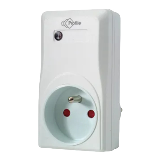
3 Remotely controlled electric sockets
PCF-300/PCF-310
We thank you for the purchase of this Profile product.
Note: It is important that you read this manual carefully
before using the product and be sure to save this manual
for possible use later.
Modern electrical installations are increasingly based on
the use of wireless control systems based upon RF
technology (Radio Frequency) and make efficient
management of all kinds of systems and devices possible
in the home. These modern systems provide for
improved protection of privacy and enhanced user-
friendliness. They perfectly combine safety and power
saving.
Setting
up
the
Setting up the main channel
1. Remove the cover from the base of the remote
control and fit the battery.
2. Adjust the channel selector as required to another
position
3. Replace the base cover
Setting up the main channel and receiver channel
Setting up the channel for receivers (electric sockets)
1. Undo the top cover on the rear of the electric sockets
using a screwdriver.
2. You will see 10 dip switches:
the first 5 are for the main channel: from 1 to 5
the last 5 are for the receiver channel: from A to E
3. Set the first 5 switches in exactly the same way with
the switches set to remote control e.g. 1 pointing up
and 2, 3, 4, 5 pointing down
4. Set the next 5 switches according to the required
ON/OFF switch on switch control A
remote
control
channel:
The red LED on the receiver illuminates when you
send an ON signal to the receivers. The red LED is
also a control instrument to see whether you have
properly fitted the receivers in the electric socket.
Conversely, when you send an OFF signal to the
receivers, the red LED will go out, and the connected
device will switch off.
Practical example
Remote control
1
2
3
4
5
Socket 1 (button on/off A)
1
2
3
4
5
A
Main channel
Socket 2 (button on/off B)
1
2
3
4
5
A
Main channel
Socket 3 (button on/off C)
1
2
3
4
5
A
Main channel
Socket 5 (extra socket: PCF-310)
(=button on/off D)
1
2
3
4
5
A
Main channel
EN - 1
B
C
D
E
Receiver channel
B
C
D
E
Receiver channel
B
C
D
E
Receiver channel
B
C
D
E
Receiver channel
Advertisement
Table of Contents

Subscribe to Our Youtube Channel
Related Manuals for Profile PCF-300


Summary of Contents for Profile PCF-300
- Page 1 The red LED on the receiver illuminates when you send an ON signal to the receivers. The red LED is We thank you for the purchase of this Profile product. also a control instrument to see whether you have Note: It is important that you read this manual carefully properly fitted the receivers in the electric socket.
- Page 2 Any damage claims in such cases will be declared null and void. Guarantee conditions The guarantee period for the PCF-300/PCF310 amounts to 2 years and commences on the date of purchase. During the guarantee period ELTRA NV will repair any defects attributable to material or production faults.
Need help?
Do you have a question about the PCF-300 and is the answer not in the manual?
Questions and answers