Table of Contents
Advertisement
Quick Links
Advertisement
Table of Contents

Summary of Contents for SOLAR AC DC DLMDWA1-ACDC-18K
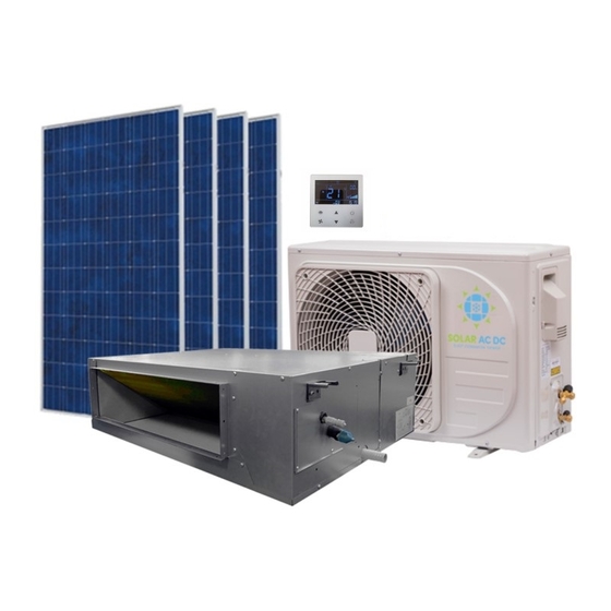
- Page 1 Photovoltaic AC/DC Ducted Air Conditioner Installation Manual...
-
Page 2: Table Of Contents
Table of contents Contents Table of contents ........................1 Table of Revisions ........................2 Model Applicability ........................2 Equipment description ......................3 Standards reference ........................ 4 Disclaimer ..........................4 Symbols used.......................... 4 ..............................5 Warning ........................... 5 Safety Precautions ........................5 Dimensions .......................... -
Page 3: Table Of Revisions
Revision Date Reason for revision Revision By 25 July 2021 Initial writing George Abernathy Model Applicability This manual applies to the following models: Table of Models DLMDWA1-ACDC-18K DLDMWA1-ACDC-24K Model DLMDA1-ACDC-18K DLMDA1-ACDC-24K Indoor unit DLWB1-ACDC-18K DLWB1-ACDC-24K Outdoor unit Revision 25 July 2021... -
Page 4: Equipment Description
Equipment description The equipment consists of an indoor unit and an outdoor unit air conditioning system. The system produces heating or cooling as required. The system can be powered in several ways. • By DC solar alone. It will start up and run on just the solar •... -
Page 5: Standards Reference
Standards reference The standards listed here may not be all applicable standards. Check local and national standards for additional applicability. Check for the latest revisions and clauses. Standards AS/NZS 1319 AS/NZS 1571 AS/ NZS 3000 As/ NZS 3500 AS/NZS 4777 AS/NZS 5033 AS/NZS 5149 IEC 62109... -
Page 6: Warning
Explosion risk, High pressure gasses used in testing and operation. High pressure gas bottle Caution risk of electric shock Warning Safety Precautions • All Electrical work must be performed by a licenced technician according to local regulations and the instructions given in this manual. •... -
Page 7: Dimensions
cause the connection points on the terminal strip to heat up, catch fire or cause electrical shock. • In certain functional environments, such as kitchens, server rooms, etc., the use of specially designed air-conditioning units is highly recommended. • For units that have an auxiliary electric heater, do not install the unit within 1 meter of any combustible materials. -
Page 8: Air Outlet Dimensions
Air Outlet Dimensions Air Inlet Dimensions Indoor unit mounting Prior to installation: Before installing the indoor unit, refer to the label on the product box to make sure that the model number of the indoor unit matches the model number of the outdoor unit. Before installing the indoor unit, you must choose an appropriate location. - Page 9 The indoor unit contains a pre-charge of inert gas. Take care when bending tubing and discharging this gas. Select the location for the indoor unit. Check that the location is suitable for pipe penetration. Check that no wiring or piping will be affected by the pipe penetration location.
-
Page 10: Outdoor Unit Mounting Instructions
Outdoor unit mounting Instructions. Install the condensate drain if required. The outdoor unit will condense water when the system is in heating mode. Consult local regulations for drainage connections. Mount the unit on an approved wall mounting bracket and secure or mount the unit on a secure waterproof surface and secure. -
Page 11: Refrigerant Pipe Specifications
Refrigerant pipe Specifications The system has a maximum ambient operating temperature of 58 degrees Celsius. The maximum pressure is 4300 Kpa / 623 Psig. Piping must be specified in accordance with AS /NZS 1571. The minimum wall thickness is 0.81 mm for 6.35mm/1/4 inch to 12.7mm / ½ inch, and 0.91 for 15.88 mm / 5/8-inch tubing. Refrigerant fill capacity Maximum Length of piping Revision 25 July 2021... -
Page 12: Addition Of Refrigerant Per Pipe Length
Addition of refrigerant per pipe length Pipe length more than 5 meters requires the addition of refrigerant. Connecting the Refrigerant piping The indoor unit contains an inert gas. Use caution when loosening the flared fittings to vent the gas. Cut the piping to length. Take care that no foreign matter enters the piping. Slide the flare nuts onto the piping. -
Page 13: Pressure Testing The System
Pressure Testing the System Fluorocarbons refrigerant must not be put into a system for the purposes of pressure leak testing. Australian refrigerant handling code of practice 5.29 High pressure nitrogen gas bottle handling. Wear appropriate PPE including eye, ear, protection, leather gloves. Precautions: Air and foreign matter in the refrigerant circuit can cause abnormal rises in pressure and could cause damage to the air conditioner. -
Page 14: Releasing The Refrigerant Into The System
Releasing the refrigerant into the system Check that the low-pressure hose is connected to the low-pressure side of the outdoor unit. Check that the system has been evacuated to 500 microns. Remove the Vacuum micron gauge to prevent damage to it. Open the low pressure and high-pressure valves by winding them out anti clockwise until seated. -
Page 15: Installation Of Solar Modules
• All wiring must be properly connected. Loose wiring can cause failures and result in product malfunction and possible fire. • Ensure that wires are not resting against refrigerant tubing, the compressor, or any moving parts within the unit. • If the unit has an auxiliary electric heater, it must be installed at least one meter away from any combustible materials. -
Page 16: Solar Array Maximum Voltage
Solar Array Maximum Voltage. The maximum Voltage Open Circuit (VOC) must be calculated to account for low temperature voltage rise. Failure to do may damage the equipment and void warranty. For guidance see AS / NZS 5033 4.2 PV array maximum voltage. The maximum Voltage Open Circuit for this equipment is 380 Vdc. -
Page 17: Solar Arrays In Parallel
Solar Arrays in Parallel If it is desired to use smaller solar panels in parallel arrays the maximum number of arrays is 2. Additional paralleled arrays may not improve, performance, and may cause the arrays or the air conditioner to be damaged. Solar Array maximum current. - Page 18 Completely cover the module with an opaque material during installation to keep electricity from being generated. Do not touch the ends of live wires. Do not wear metallic rings, watchbands, ear, nose lip rings or other metallic devices while installing or troubleshooting photovoltaic systems.
-
Page 19: Solar Array Mechanical Installation
Solar Array Mechanical installation Selecting an installation place: • Select a suitable place for installation of the solar modules. The modules should not be shaded during the solar window part of the day. • The module should be facing north in the southern latitudes for best power generation. - Page 20 Roof Mounting: When installing the modules on a roof ensure that they are securely fastened and cannot fall because of wind or snow loads. When installing on a roof, ensure that the roof construction is suitable. In addition, any roof penetration required to mount the module must be properly sealed to prevent leaks.
- Page 21 Solar Array Wiring The array is formed of modules in series. The switch disconnectors must be approved for disconnecting solar DC under load. The MC 4 connectors must be approved and from the same manufacturer at each join. Mismatching connectors can cause failure and possible fire. General installation: •...
-
Page 22: Earth Fault Protection Solar Dc
Earth Fault Protection Solar DC The outdoor unit solar controller has DC earth leakage detection. When the PV positive and PV negative currents are not equal relays RY1 & 2 will open and disconnect DC power to the Unit. An error code will be displayed on the outdoor unit AC/DC booster LED. The LED will flash 7 times. -
Page 23: Solar Disclaimer
To be placed in the Distribution board. Solar Disclaimer Because the use of this manual and conditions or methods of installation, operation, use and maintenance of the photovoltaic (PV) product are beyond our control, we do not take any responsibility and expressly disclaim liability for loss, damage, or expense arising out of or in any way connected with such installation, operation use or maintenance. -
Page 24: Electrical And Gas Leak Checks
Electrical and Gas Leak checks. Gas Leak checks Prior to the test run check for gas leaks using the following methods: Soap and water method Using a soft brush, apply soapy water or liquid detergent to all pipe connection points on the indoor and outdoor unit. -
Page 25: Maintenance
Before the test run: Verify that: • The unit’s electrical system is safe and will operate properly. • The gas leak checks have been performed. • Confirm that the low- and high-pressure valves are fully open. The test should run for at least 30 minutes. Connect power to the unit. -
Page 26: Operating Instructions
Outdoor unit: Check that the outdoor unit airflow is not obstructed by objects on or around it, and vegetation. Examine the general condition of the outdoor unit. Check the fan for foreign objects. Check the fins for deformation. Check the insulation of the piping for security and integrity. Remove Vegetation that is shading the solar modules. -
Page 27: Wired Control Operation
Wired Control operation Display and functions: Button Functions Parameter Setting / 1. Short press to enter timing mode. Timing 2. Long press >5 seconds to enter parameter setting mode 1. Short press to adjust fan speed. Fan Speed / Time 2. -
Page 28: Detailed Wired Control Operation
Detailed Wired Control operation On off: On Display Off Display Short press of the on off button (5) starts and stops the unit. Modes The mode button cycles through from Auto to Heating and back to Auto. Set Temperature Select the desired mode and using the UP and DN buttons set the desired temperature. Revision 25 July 2021 Page 27 of 36... - Page 29 Set Time. Press and hold the Fan button for 5 seconds. The time display will flash on and off at a 1 second rate. Press the UP or DN button to change the time. When the desired time has been set press the mode button to exit. Revision 25 July 2021 Page 28 of 36...
-
Page 30: Timing Periods
Timing Periods The wired control can set up to three timing periods per day. Setting: Short press the (1) Parameter Setting / Timing button. The first timing period will blink. Pressing the (1) Parameter Setting / Timing button again will cycle through the timing periods. -
Page 31: Ac Limiter Mode Permanent Setting
The timing period that is being executed is displayed in the lower right of the display. AC Limiter Mode Permanent setting To permanently enable the AC limiter mode. • Press parameter until Timer 1 is visible. • Select up or down to turn timer 1 on. •... -
Page 32: Android Or I Phone App
Android or I phone app. Scan the QR code in the owners- manual. 1. Download the app. 2. Turn the air conditioner on. • Press the Parameter Setting / Timing button (1) until the WIFI icon flashes. • Press the Mode button (6) •... -
Page 33: Troubleshooting And Repair
1. Use the app to control the air conditioner anywhere via WIFI. Observe the power saving data and view the power consumption by hour/day/month/year. Troubleshooting and Repair For Repair parts and service information contact 1300 46 22 32 acdc@solaracdc.com.au Warning disassembly of the units can result in an electric shock hazard. This unit employs multiple sources of supply and care must be taken that all supplies are turned off and energy storage devices disconnected. - Page 34 Issue Possible Causes Unit does not turn on The Unit has a 3-minute protection feature that prevents the unit when pressing the from overloading. The unit will not restart within three minutes of on off button being turned off. The unit may change its setting to prevent frost from forming on the unit.
- Page 35 Problem Possible Causes Solutions Temperature setting may be higher than ambient Lower the temperature room temperature setting The heat exchanger on the Clean the affected heat indoor or outdoor unit is dirty exchanger Remove the filter and clean The air filter is dirty it according to instructions Turn the unit off, remove the The air inlet or outlet of...
-
Page 36: Ac/Dc Booster Error Code
Problem Possible Causes Solutions The unit may stop operation or continue to run safely. If the Error code appears in indicator light continues to display an error code, wait for the window display about 10 minutes. The problem may resolve itself. If not, of indoor unit: disconnect both solar and grid power, then connect it again •... -
Page 37: Error Code List
Error Code list Revision 25 July 2021 Page 36 of 36...
Need help?
Do you have a question about the DLMDWA1-ACDC-18K and is the answer not in the manual?
Questions and answers