Table of Contents
Advertisement
Quick Links
Advertisement
Table of Contents

Related Manuals for DAYLIFF DGW 200P


Summary of Contents for DAYLIFF DGW 200P
- Page 1 Welding Generator Installation & Operating Manual...
- Page 3 INDEX GENERATOR SPECIFICATIONS 2. SYMBOLS & WARNINGS OPERATION MAINTENANCE TROUBLE SHOOTING WARRANTY © Davis & Shirtliff Ltd 2022 Contents herein are not warranted...
-
Page 4: Generator Specifications
Installation Manual is therefore important, though should there be any queries they should be referred to the equipment supplier. 1. GENERATOR SPECIFICATIONS The Dayliff DGW welding generator is a dependable, quality product specially designed for welding and generating simultaneously or separately. Particular features include: •... - Page 5 Starter Period Capacity Rated Engine (kg) Capacity Power (Hrs) (cc) (kVA) (kVA) Model (litres) (HP) DGW 200P GK420 10.5 12.5 DGW 200D LA186FA Electric DGW 300D LA290F 1070 WELDING DATA Welding Performance Welding Rod Currents (A) Model No Load Operation Max.
-
Page 6: Symbols And Warnings
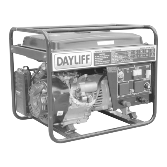
Part Names Fuel Tank Fuel Filler Cap Current Adjusting Knob AC Output Air Cleaner Switch Recoil Starter Welding Terminal Engine Control Lever Starting Handle (Start/Stop Lever) Oil Drain Plug Oil Filler Cap/Dipstick 2. SYMBOLS & WARNINGS Check the fuel requirements and use recommended fuel engine. - Page 7 Operate the generator on a level surface, to avoid fuel spillage WARNING Exhaust gas contains poisonous carbon monoxide. Never use the generator in poorly ventilated locations. If indoor operation is unavoidable, provide proper ventilation. WARNING Never touch the mufer or mufer cover while the engine is running as it may be hot.
-
Page 8: Operation
Always wear a helmet, safety shoes and protective clothes. Keep pets and children away from the generator when it is in operation. WARNING Battery electrolyte contains sulphuric acid. Protect eyes, skin and clothing. In case of contact, ush thoroughly with water and get prompt attention, especially if eyes are affected. - Page 9 Selection and handling of the lube oil Inlet of Lubricant Set the generator on a level ground, fill the engine oil through the inlet of lubricant. Recommended Value Usable Limit Ÿ To check the oil level, simply dip the dipstick into the pan. Do not screw the dipstick. Upper Level (H) Lower Level (H) Ÿ...
- Page 10 Do not add oil into the machine when the engine is running. CAUTION Oil Drain Plug Oil Filler Cap/Dipstick Check Air Cleaner Element Ÿ Loosen the wing nut, detach the cover of air cleaner and remove the element. Ÿ The air cleaner element must be changed when the output of engine decreases or the color of exhaust is abnormal.
-
Page 11: Bleeding Fuel Line
Cover Check Diesel Welding Machine Ÿ Turn off the main switch and any other loads such as the light and motor switches. Voltmeter Circuit Breaker Starting Switch DC Output AC Output Ÿ Be sure to turn off the main switch before starting the generator. If the switch is not on the ‘OFF’... - Page 12 Ÿ On the other hand, too much oil is dangerous because the oil may combust and cause a sudden and excessive rise in engine revolutions, so before operating the machine, be sure to check the oil and supply oil to the specified level. Break In Operation When the generator is still new, application of heavy loads may shorten the life of the engine.
- Page 13 2. Put the engine speed lever in the ‘RUN’ position. Engine-Control Lever Starter/Run Engine Speed Lever Stop 3. Pull out the recoil starting handle. Ÿ Pull out the handle to the point where it feels resistant and then return it to the initial position.
- Page 14 Plug Electric Starting Ÿ Open the fuel cock. Ÿ Turn the engine control lever to‘RUN’ position. Ÿ Turn the starting key at clockwise to ‘START’ position. Ÿ When the engine starts running the key returns automatically to initial position. Ÿ If the starter motor doesn’t start after a few seconds, wait for about 15 seconds before attempting to start again.
- Page 15 Ÿ Abnormal sound or vibration. Ÿ The engine misfiring or running rough. Ÿ Color of the exhaust gas? (either black or white?) If the above signs are observed stop the engine and consult the nearest Dayliff retailer. Engine Speed Limiting...
-
Page 16: Operating Procedures
Ÿ Welders, welding tongs, welding wires and joints should be well connected with good insulation. Ensure there is no overheating of the wiring, the wiring terminal must not be exposed, it requires cover with insulating tape. Ÿ The length of the wire between the welding machine and the welding clamp should be less than10 metres, maximum length should not exceed 20 metres. - Page 17 For electric principle diagram of generator, refer to the following drawing Electrical Schematic Diagram Dual Voltage Electrical Schematic Diagram...
- Page 18 AC Application Ÿ Start the engine and ensure the pilot lamp turns on. If it does not, the filament may be burnt out. Ÿ The speed of generator must reach rated speed. Ÿ Generator is ready to take on load when the indicator of voltmeter reads 230+10% (50Hz) on the panel of control box.
- Page 19 To prevent the possibility of creating a spark near the battery, always connect the charging cables to battery rst and only then to the generator. When disconnection, you should CAUTION disconnect the cables at the generator rst Charge the battery in a well ventilated place. Before charging, remove the cap from each cell of the battery.
-
Page 20: Maintenance
Ÿ Slowly pull out the recoil handle until pressure is felt (that is, to the point in the compression stroke where the intake and exhaust valves are closed), and leave the handle in this position. This prevents rust from forming while the engine is not in use. If the engine keeps on running even after the control lever is locked at the ‘STOP’... - Page 21 Changing Engine Oil (every 100hrs) Ÿ Remove the oil filler cap. Ÿ Remove the drain plug and drain the used oil while the engine is still warm. The plug is located on the bottom of the cylinder block. Ÿ Tighten the drain plug and refill with the recommended oil. Ÿ...
- Page 22 All these require special tools and skills. Do not perform the injection nozzle test near an open re or any other kind of re. The fuel spray may ignite. Do not expose bare skin to the fuel CAUTION spray as it may penetrate the skin and cause bodily injury. Checking and replenishing battery uid This diesel engine uses a 12V battery.
-
Page 23: Troubleshooting
5. TROUBLE SHOOTING Problem Possible Cause Solution Add fuel oil Fuel oil is not enough The switch is not at ‘ON’ Turn it to ‘ON’ position position The high pressure pump and Remove the oil nozzle out and oil nozzle can not inject oil or repair it at test table the oil amount is not enough The control lever of speed is... - Page 24 If electricity is not generated, take the generator to a Dayliff retailer. Incase of question or problem, note the below parameters from the engine and report to a Dayliff retailer. • Mode of diesel generator and serial number of engine and alternator.
-
Page 25: Terms Of Warranty
6. TERMS OF WARRANTY i) General Liability In lieu of any warranty, condition or liability implied by law, the liability of Dayliff in Ÿ respect of any defect or failure of equipment supplied is limited to making good by replacement or repair (at the Company’s discretion) defects which under proper use appear therein and arise solely from faulty design, materials or workmanship within a specified period. - Page 28 INS302H-11/22...
Need help?
Do you have a question about the DGW 200P and is the answer not in the manual?
Questions and answers