Subscribe to Our Youtube Channel
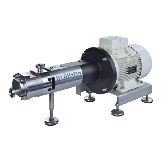
Summary of Contents for Jung HYGHSPIN BASIC
- Page 1 Disassembly and assembly instructions Screw Spindle Pump Block Design Jung Process Systems GmbH Auweg 2 · 25495 Kummerfeld · Deutschland Tel.: +49 4101 7958 - 140 Fax: +49 4101 7958 - 142 jung-process-systems.de...
-
Page 3: Table Of Contents
Contents 1 General information ..........................1 2 Removal of the pump from the unit ..................... 1 3 Disassembling the feed screws and mechanical seals ................. 1 4 Assembling the feed screws and mechanical seals ................2 5 Removing the bearing support ......................4 6 Assembling bearing support ......................... -
Page 4: General Information
1 General information These instructions are designed to be used in conjunction with the sectional drawing. For reasons of economy and operational safety the following parts should not be reused: Flat gaskets (item 128) O-rings (at the mechanical seal) ... -
Page 5: Assembling The Feed Screws And Mechanical Seals
Undo clamping nuts (item 18) by turning counter-clockwise Remove bottom stud bolts (item 9) Mark teeth position of feed screw towards shaft Remove pair of feed screws (item 6) Remove rotating units of the mechanical seals ... - Page 6 Remove stud bolts again (item 9) Mount rotating units of the mechanical seals Position feed screws on a level surface so that they intermesh and rotate them against each other until both faces lie completely on the surface Type NR Type SR Feed screws with rightward rotation with...
-
Page 7: Removing The Bearing Support
Screw in stud bolts (item 9) (do not insert completely) Mount pump casing (item 2). When the main direction of rotation is rightward, the "VS" stamped on the face must point down towards the cover (clockwise when looking towards the end of the drive shaft) ... -
Page 8: Assembling Bearing Support
Pull shafts (item 7) out of the bearing casing (Pos. 4) Remove front securing V ring (item 125) Move spacer sleeve (item 17) Remove angular contact ball bearings (item 107) with the aid of an extractor ... - Page 9 Push shaft (item 7) into the bearing casing. The lubrication holes of the needle bearings should be aligned upwards Mount spacer sleeves (item 16) Mount bearing cover with groove downward (item 14) Mount Nilos ring (item 121) and bearing cover (item 15) ...
-
Page 10: Adjustment Of Flank Clearance
Press shaft seal rings (item 106) into bearing casing (item 4). Use the manufacturer's assembly tools for this Mount gear cover (item 5) with flat gasket (item 128) Screw in cylindrical screws (item 122) Screw in oil drain screw (item 19) and fill with gear oil via the locking screw up to the oil level indicator marking ... - Page 12 Jung Process Systems GmbH Auweg 2 · 25495 Kummerfeld · Deutschland Tel.: +49 4101 7958 - 140 Fax: +49 4101 7958 - 142 jung-process-systems.de...


Need help?
Do you have a question about the HYGHSPIN BASIC and is the answer not in the manual?
Questions and answers