Table of Contents
Advertisement
Quick Links
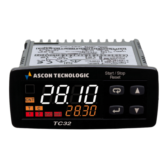
TC 32
TIMER/PULSE COUNTER/
DIGITAL ELECTRONIC
POWER LIMITER
User Manual
23/01 - Code: ISTR_M_TC32_E_01_--
ASCON TECNOLOGIC S.r.l.
Viale Indipendenza 56, 27029 - VIGEVANO (PV) ITALY
TEL.: +39 0381 69871 - FAX: +39 0381 698730
sito: http:\\www.ascontecnologic.com
e-mail: info@ascontecnologic.com
PREFACE
D
This manual contains the information necessary for
the product to be installed correctly and also instruc-
tions for its maintenance and use; we therefore recom-
mend that the utmost attention is paid to the following
instructions and to save it.
This document is the exclusive property of Ascon Tecnologic
S.r.l. which forbids any reproduction and divulgation, even
partially, of the document, unless expressly authorized.
Ascon Tecnologic S.r.l. reserves the right to make any formal
or functional changes at any moment and without any notice.
Ascon Tecnologic S.r.l. and its legal representatives do not
assume any responsibility for any damage to people, things
or animals deriving from violation, wrong or improper use or
in any case not in compliance with the instrument features.
D
Whenever a failure or a malfunction of the device may
cause dangerous situations for persons, thing or animals,
please remember that the plant has to be equipped with
additional devices which will guarantee safety.
Ascon Tecnologic - TC32- - OPERATING INSTRUCTIONS - PAG. 1
Index
1. Instrument description ............................................... 1
1.1
General description ........................................................... 1
1.2
Front panel description ..................................................... 2
2. Programming ............................................................... 2
2.1
Set Points (timings) programming ..................................... 2
2.2
Standard mode parameters setting ................................... 3
2.3
Parameter protection using a password ............................ 3
2.4
(parameters programming level) ......................................... 3
2.5
Reset parameters to default value .................................... 3
2.6
Keyboard lock function ...................................................... 3
3. Usage warnings ........................................................... 4
3.1
Allowed Usage .................................................................. 4
4. Installation warnings ................................................... 4
4.1
Mechanical Mounting ........................................................ 4
4.2
Electrical connections ....................................................... 4
5. Operating mode ........................................................... 5
5.1
Timer, Pulse counter or Power limiter ............................... 5
5.2
Operation as a timer ......................................................... 5
5.3
Operation as a Pulse counter ........................................... 9
5.4
Operation as a Power limiter ........................................... 11
6. Accessories ............................................................... 11
6.1
Parameters configuration with A01 ................................. 11
6.2
Parameters configuration with AFC1 .............................. 12
7. Problems and maintenance ...................................... 12
7.1
Cleaning .......................................................................... 12
7.2
Disposal .......................................................................... 12
8. Warranty and repairs ................................................. 12
9. Programmable parameters table .............................. 13
10. Technical data ............................................................ 16
10.1 Electrical data ................................................................. 16
10.2 Mechanical characteristics .............................................. 16
10.3 Functional features ......................................................... 16
11. How to order .............................................................. 16
1. INSTRUMENT DESCRIPTION
1.1
General description
TC32 is a microprocessor based digital timer/pulse coun-
ter/power limiter.
The instrument used as a timer offers the possibility to
program: up to 3 timings (Set point), 6 operating modes for
OUT1 output, 10 operating modes for OUT2 output, 4 time
scales (which allow a count from a maximum of 9999 hours
to a minimum of 0.01 seconds), 6 counting enabling func-
tioning modes and 2 counting modes (UP or DOWN).
The instrument used as a pulse counter offers the pos-
sibility to program: up to 2 Set points, 3 operating modes
for OUT1 output, 4 operating modes for OUT2 output and
offers the possibility of counting division.
Moreover, the instrument can also be used as a power
limiter by programming a duty-cycle from 0 ÷ 100% and a
total cycle time from 1 ÷ 900 s.
The upper 4-digit display normally shows the counting
status while the lower 4-digit display the selected timing
(set-point), the status of the outputs is shown by 2 LEDs.
The instrument has 1 counting/counting enabling input
(CNT) and 1 digital input with programmable operation
(RESET or reverse counting) whose signals can come from
free of voltage contacts, from devices with NPN or PNP
transistor output. It can have up to 2 relay outputs or for
driving Solid State Relays (SSR).
Advertisement
Table of Contents

Subscribe to Our Youtube Channel
Related Manuals for Ascon tecnologic TC 32


Summary of Contents for Ascon tecnologic TC 32
-
Page 1: Table Of Contents
0.01 seconds), 6 counting enabling func- Ascon Tecnologic S.r.l. reserves the right to make any formal tioning modes and 2 counting modes (UP or DOWN). or functional changes at any moment and without any notice. -
Page 2: Front Panel Description
: RST input status; 15 Timer separator point: Indicates the separation be- tween hours and minutes, minutes and seconds, sec- onds and hundredths of a second when the instrument operates as a Timer. Ascon Tecnologic - TC32- - OPERATING INSTRUCTIONS - PAG. 2... -
Page 3: Standard Mode Parameters Setting
5 s, after which the label LF appears on the display and all the key functions will be available again. Ascon Tecnologic - TC32- - OPERATING INSTRUCTIONS - PAG. 3... -
Page 4: Usage Warnings
RECOMMENDED PANEL CUTOUT Ascon Tecnologic - TC32- - OPERATING INSTRUCTIONS - PAG. 4... -
Page 5: Operating Mode
If the counting is finished, pressing the key carries out the Reset-Start command at the same time. i. F ct = 1 RESET 0.1.2.3.4 .5.6.7.0 COUNT START STOP START STOP RESET Ascon Tecnologic - TC32- - OPERATING INSTRUCTIONS - PAG. 5... - Page 6 -Start/Stop button (if t. U Ft = 2) acts in exactly the same way as the CNT input. i. F ct = 5 RESET 0.1.2.3 0.1.2.3.4. 0 COUNT STOP RESET STOP START START RESET RESET Ascon Tecnologic - TC32- - OPERATING INSTRUCTIONS - PAG. 6...
- Page 7 F. o 2t = 2 of Set point. S.t1 Start F. o 1t = 1, F. o 2t = 4 (e.g.: Fo1t = 1) OUT1 Start S.t1 OUT2 OUT1 S.t3 Reset OUT2 Reset Ascon Tecnologic - TC32- - OPERATING INSTRUCTIONS - PAG. 7...
- Page 8 F. o 1t = 3, F. o 2t = 10 Start S.t1 S.t2 Start S.t2 S.t2 OUT1 S.t1 S.t3 S.t1 S.t3 S.t1 S.t3 S.t1 S.t1 S.t3 S.t1 OUT2 OUT1 Reset OUT2 Reset Ascon Tecnologic - TC32- - OPERATING INSTRUCTIONS - PAG. 8...
-
Page 9: Operation As A Pulse Counter
EndC = 0 or steady ON if EndC = 1. values and therefore once the value 0 (count UP) or the Set point value (count DOWN) has been reached, any inversion count pulse will not be acquired. Ascon Tecnologic - TC32- - OPERATING INSTRUCTIONS - PAG. 9... - Page 10 2C = 2 current count: Resets the count; INPUT Stops the count and stores the value reached. S.C1 S.tr S.C1 S.tr Out1 e.g.: f. o 1C = 1 Out2 Ascon Tecnologic - TC32- - OPERATING INSTRUCTIONS - PAG. 10...
-
Page 11: Operation As A Power Limiter
F. o 2P = 2 - As Out1 with negated logic Out2 functions as Out1 but with inverted logic; F. o 2P = 3 - Out2 active Out2 is active when the Power limiter is active. Ascon Tecnologic - TC32- - OPERATING INSTRUCTIONS - PAG. 11... -
Page 12: Parameters Configuration With Afc1
The defected product must be shipped to Ascon Tecnologic with the detailed description of the failures found and without any fees or charge for Ascon Tecnologic, safe different agreements. -
Page 13: Programmable Parameters Table
6 S. t 2 and S. t 3; 7 S. t 1, S. t 2 and S. t 3; keys 8 Only S. t 1 directly using keys. 9 Only S. t 2 directly using Ascon Tecnologic - TC32- - OPERATING INSTRUCTIONS - PAG. 13... - Page 14 6 S. C 2 and S. t r; 7 S. C 1, S. C 2 and S. t r; keys 8 Only S. t 1 directly using keys. 9 Only S. t 2 directly using Ascon Tecnologic - TC32- - OPERATING INSTRUCTIONS - PAG. 14...
- Page 15 2842 Inputs logic NPN/PNP t. L i P PNP. Display flashing at count end 0 Display flashing at count end; 2843 EndC (Timer or Counter mode) 1 Display steady ON at count end. Ascon Tecnologic - TC32- - OPERATING INSTRUCTIONS - PAG. 15...
-
Page 16: Technical Data
99 s 99 hundreds of second; Display resolution: Based on the time scale used: hours, minutes, seconds, hundreds of second; Timer verall accuracy: ±0.1 fs; Timer input delay: 15 ms max.; Ascon Tecnologic - TC42- - OPERATING INSTRUCTIONS - PAG. 16...
Need help?
Do you have a question about the TC 32 and is the answer not in the manual?
Questions and answers