Table of Contents
Advertisement
Quick Links
Advertisement
Table of Contents

Related Manuals for Triamec TSP700-10


Summary of Contents for Triamec TSP700-10
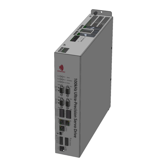
- Page 1 Hardware Manual TSP700-10, TSP700-20, TSP700-40, Revisions 0 to 2 Keep all manuals belonging to this product during its life span. Pass all manuals to future owners and users of this product. This English version is the original version of the product manual.
-
Page 2: Table Of Contents
Table of Contents 1 General..............................6 1.1 Target Group...........................6 1.2 Standard Used..........................7 1.3 Symbols Used..........................7 2 Safety...............................8 2.1 Intended Use...........................9 2.1.1 Cabinet..........................9 2.1.2 Power Supply........................9 2.1.3 Motors..........................9 2.1.4 Safety..........................9 2.2 Prohibited Use..........................9 2.3 Responsibility..........................10 2.4 EC Declaration of Conformity......................10 3 Nomenclature............................11 3.1 Order Key Codes...........................11 3.1.1 DCV...........................11 3.1.2 A... - Page 3 Table of Contents 5.1.4 Communication........................18 5.1.5 In-Drive Tama Programming.....................18 5.1.6 PC Programming.......................18 5.2 Electrical Specifications.........................19 5.2.1 Internal Power Supply.......................19 5.2.2 Drive..........................19 5.2.3 Rated Currents........................21 5.3 EMC Requirements according to EN 61800-3................21 5.3.1 Motor and Cable.......................21 5.3.2 Shielding...........................21 5.4 Safety Requirement according to EN 61800-5-1................21 5.4.1 AC Supply..........................21 5.4.2 Protective Earthing Conductor Current................22 5.4.3 Extra Low Voltage Connection..................22...
- Page 4 Table of Contents 7.2.3 Wiring and Shielding......................32 7.2.4 Final Check........................32 7.3 Overview of Servo Drive Connections..................33 7.3.1 TSP700-10, TSP700-20......................33 7.3.2 TSP700-40.........................34 7.4 Connectors and Terminals......................35 7.5 Electrical Supplies (X1, X2)......................37 7.5.1 AC-Power Supply (X1).......................37 7.5.2 24V Logic Supply (X2).......................38 7.6 Brake Resistor Connection (X9 or X90/X91)..................39 7.6.1 Internal Brake Resistor(s)....................39...
- Page 5 Table of Contents References.............................67 Glossary..............................68 Revision History.............................69 During operation there are hazards, with the possibility of death, serious injury or mater- ial damage. The operator must ensure that the safety instructions in this manual are fol - lowed and that all personnel responsible for working with the drive have read and under- DANGER stood the product manual.
-
Page 6: General
1 General Dear user! This manual describes the TSP700 series of Triamec servo drives. The TSP700 is a single axis servo drive for up to 700V with integrated power supply. In order to start operation of your drive quickly and without problems, read this manual before carrying out any operation with the Triamec hardware. -
Page 7: Standard Used
General Standard Used 1.2 Standard Used Standard Content EN ISO 13849-1:2015 Safety of machinery: Safety-related parts of control systems IEC 60204 Safety of machinery: Electrical equipment of machines IEC 60364 Low-voltage electrical installations EN 60529:1989 Degrees of protection provided by enclosures (IP Code) IEC 60664-1:2020 Insulation coordination for equipment within low-voltage systems IEC 60721-3-2:2018... -
Page 8: Safety
2 Safety Notice: The user must have read and understood this manual before carrying out any operation on Triamec Notice: hardware. The safety information must be observed every time to avoid hazards and/or material damage. Triamec Motion AG disclaims all responsibility to possible industrial accidents and material damages if the procedures &... -
Page 9: Intended Use
Safety Intended Use 2.1 Intended Use Servo drives are safety components for installation into stationary electric, industrial machines and commercial systems. Safety Information The manufacturer of the machine must produce a risk assessment for the machine and take appropriate measures to ensure that unforeseen movements do not result in personal injury or material damage. CAUTION 2.1.1 Cabinet The servo drive must only be operated in a closed control cabinet, as defined in chapter 5.10, which... -
Page 10: Responsibility
To protect against danger, it may be more beneficial to keep individual servo drives running or to initiate specific safety sequences. 2.4 EC Declaration of Conformity Triamec Motion AG provides EC declarations of conformity upon request to info@triamec.com. Notice: This product can cause high-frequency interference in non industrial environments. This can require Notice: measures for interference suppression like additional external EMC filters. -
Page 11: Nomenclature
- EH ENNO Table 3.1: Example part number of a TSP700-10-EH-ENNO-XC servo drive with 700V nominal voltage, 10Arms per axis and EtherCAT fieldbus, supporting electrical commutation frequencies >=600Hz. It has an additional encoder module on extension slot 0. The servo drive further includes the software option for eccentricity compensation. -
Page 12: Commutation Speed
3.2 Accessories Triamec Motion AG delivers some useful accessories for the servo drives. The table below shows the most helpful items. For more information contact Triamec Motion AG or visit the Triamec homepage www.triamec.com. -
Page 13: Handling
4 Handling 4.1 Nameplate The nameplate depicted below is attached to the side of the servo drive. Drive Hardware Type Electrical Serial Number Supply Output Voltage Hardware and Current Revision Max. Ambient Enclosure Temperature Rating Figure 1: Nameplate of the TSP series servo drives 4.2 Transport ... -
Page 14: Storage
Handling Transport TSP700 Temperature -25°C (-13°F) and +70°C (+158+C), max. rate of change 20K / hour Humidity less than 95% at max +40°C without condensation Shock limit Dropping height of packed device max. 0.25m Frequency Amplitude Acceleration Vibration limit 2Hz ≤ f < 9Hz 3.5mm not applicable 9Hz ≤... -
Page 15: Packaging
Handling Packaging 4.4 Packaging The servo drives come in a recyclable cardboard box with the following content. TSP700-10 TSP700-20 TSP700-40 350 x 320 x 85mm 380 x 380 x 200mm Dimensions W x D x H Labelling label on box Delivery content ... -
Page 16: Disposal
Triamec Motion AG. 4.7 Disposal We take old devices and accessories back for professional disposal (WEEE-2002/96/EC-Guidelines). Transport costs are the responsibility of the sender. Disassemble the equipment as described in chapter 4.5 and send it to Triamec Motion AG. HWTSP700_0-2_HardwareManual_EP001 2023-01-31... -
Page 17: Technical Description
The Triamec digital servo drives TSP700 series master even the most difficult motion problems: Highly dynamic positioning tasks or on the other hand very precise motion. This series is available for two fieldbuses, Tria-Link a flexible fieldbus developed by Triamec, and Ether- CAT, a standardized fieldbus. -
Page 18: Communication
Technical Description Features 5.1.4 Communication Stand-alone operation Tria-Link fieldbus with host (PC) by PCI-/PCI-Express card TLxxx and inter servo drive communication with up to 200Mbps. EtherCAT servo drives with standard EtherCAT COE slave, may be used as DC-master function. 5.1.5 In-Drive Tama Programming ... -
Page 19: Electrical Specifications
Technical Description Electrical Specifications 5.2 Electrical Specifications 5.2.1 Internal Power Supply Internal Power Supply TSP700-10 TSP700-20 TSP700-40 Units 3-phase or 3-Phase AC Voltage (L-L) 208...480 ± 10% (1-phase) 1-phase AC voltage 208...480 ± 10% (Not Recommended) AC-Line Input Nominal frequency 50...60... - Page 20 Technical Description Electrical Specifications ous (at 50kHz) Logic Supply Voltage (PELV) Max. Current Temperature Various sensors in the servo drive (temperature range -40°C … Supervision 125°C), one external sensor per motor, supported sensor types: KTY83, KTY84, PT100, PT1000, PTC-1K (temperature range -40°C … 300°C) Position General The supply delivers 5.2V and maximum 250mA and is short-circuit...
-
Page 21: Rated Currents
Technical Description Electrical Specifications 5.2.3 Rated Currents The maximum permissible servo drive output current and the peak current are dependent on the power stage switching frequency, the servo drive type and the ambient temperature. All the specifications in the table above are given for an ambient temperature ranging from +5°C (41°F) to +40°C (104°F). -
Page 22: Protective Earthing Conductor Current
Technical Description Safety Requirement according to EN 61800-5-1 Overvoltage category 3 capable of delivering less than 40kArms, symmetrical amperes (prospective current according to EN 60269-1) The network must be a TN-C-S with center earth or similar. 5.4.2 Protective Earthing Conductor Current There are two 82nF Y-capacitors between DC-Bus and earth. -
Page 23: Dynamic Braking
Technical Description Dynamic Braking 5.6 Dynamic Braking A system of a motor coupled with a load has a certain amount of energy. This energy is mainly kinetic when the load is moving or rotating. While stopping these loads, the energy must either be stored or dissipated. -
Page 24: Safety Function Sto
TwinCat users: Be aware that the system level designer might have chosen to disable direct error event reporting from the Triamec module to the user. It is at the system level designers responsibil- ity to propagate the plc-axis errors during commissioning in this case. - Page 25 Technical Description Safety Function STO 5.7.3.1 Standard Case If STO is activated simultaneously on both channels as intended, the servo drive will enter a safe state: The warning state Not-ReadyToSwitchOn/STO-Active is entered when STO is activated from the switched off state ReadyToSwitchOn. This state is left without reset, if the STO is inactivated.
-
Page 26: Safety Characteristic Data
Technical Description Safety Function STO 5.7.4 Safety Characteristic Data The following table shows safety specification (in addition to the electrical STO specification in chapter 5.2.2). Value Safety level SIL3 Ple CAT 3 3E-9 h 2E-4 (Proof-Test Interval equals Mission Time) 95% for STO (Hardware Fault Tolerances HFT1) 96% for Diagnostics (Hardware Fault Tolerances HFT0) Type... -
Page 27: Commutation Frequency Limitation
The European Union issued export restrictions for frequency converters to some countries. Under some conditions, export to these countries is simplified. Triamec servo drives for simplified export contain a limitation of the commutation frequency described in this document. For the correct ordering details refer to chapter 3.1.4. -
Page 28: Mechanical Specifications
Technical Description Mechanical Specifications 5.9 Mechanical Specifications TSP700-10 TSP700-20 TSP700-40 Weight 5000g 10000g Dimensions W x H x D 69 x 315 x 295 mm³ 152 x 315 x 308 mm³ 5.10 Ambient and Mounting Conditions TSP700 Site Altitude up to 1000m above sea level without restriction, higher than 1000m above sea level with reduced power 1% per 100m, max. -
Page 29: Mechanical Installation
6 Mechanical Installation 6.1 Safety Instructions Symbol Safety Information - There is a danger of electrical shock by high EMC level which could result in injury, if the servo amplifier (or the motor) isn't properly EMC-grounded. - During installation work strictly avoid that drill chips, screws or other foreign substances drop into any CAUTION device. -
Page 30: Guide To Mechanical Installation
Mechanical Installation Guide to Mechanical Installation 6.2 Guide to Mechanical Installation The following notes help to carry out the mechanical installation. 6.2.1 Site Gap B The servo drive should be mounted into a lockable control cabinet. Refer to chapter 5.10. ... -
Page 31: Electrical Installation
7 Electrical Installation 7.1 Safety Instructions Symbol Safety Information There is a danger of electrical arcing with serious personal injury. Never connect or disconnect electrical connections while power of any source is on. Isolate the device from the power lines before working on it. -
Page 32: Guide To Electrical Installation
Electrical Installation Guide to Electrical Installation 7.2 Guide to Electrical Installation The following notes help to carry out the electrical installation. The installation procedure is described as an example. A different procedure may be appropriate or necessary, depending on the application of the equipment. -
Page 33: Overview Of Servo Drive Connections
BRint connect BRint to BR- Aux Gnd -24V+ Functional Auto- Mains SafeOut F1 Safety Mains Ferrite Transformer Fuse Switch SafeOut F2 SafeOut F3 SafeOut F4 SafeOut F5 SafeOut F6 X5/X6 Field bus Figure 3: Connection diagram TSP700-10, TSP700-20 HWTSP700_0-2_HardwareManual_EP001 2023-01-31... -
Page 34: Tsp700-40
Electrical Installation Overview of Servo Drive Connections 7.3.2 TSP700-40 Axis 0 Drive TSP700-40 Feedback DigIn1 Switch DigIn2 DigIn3 DigIn4 DigIn5 DigIn6 Temp Brake P24V P24ret Motor DigOut1 DigOut2 +24VDC 24VDC Isolation Ground Ground Ext. Brake Resistor Int. Brake Resistor, BRint STO Ch1 connect BRint to BR- Safety... -
Page 35: Connectors And Terminals
Triamec TAM System Explorer. In/Out The USB connector (mini-B) can be connected to a Microsoft® Windows® based note- book/PC. It’s possible to monitor and configure the servo drive within Triamec TAM System Explorer. In/Out Brake resistor Weidmüller, BVZ 7.62IT/04/180MF2 SN BK BX... - Page 36 Electrical Installation Connectors and Terminals Connector Direction Terminals Type Details X20/X21 Encoder 15 pin Sub-D (female) high-density connector 7.11 X30/X31 In/Out Digital I/O Weidmüller, B2CF 3.50/12/180LH SN BK BX 7.12 Order no.: 1375750000 (for coding, see option Motor Weidmüller, BVF 7.62HP/4/180MF4 BCF/06 SN BK BX SP150 SO 7.13 Order-No.: 2815680000, 4 pins 7.62mm pitch &...
-
Page 37: Electrical Supplies (X1, X2)
X1 at the top side of the servo drive. As discussed in chapter 5.4.2 there must be two Figure 6: AC-power supply connector (X1) TSP700-10, TSP700-20 protective earth connections. The first PE is connected through X1 pin 4 and the second connection is... -
Page 38: Logic Supply (X2)
Electrical Installation Electrical Supplies (X1, X2) 7.5.2 24V Logic Supply (X2) The servo drive requires a 24V DC supply (PELV type mandat- ory) for its internal logic and for the supply of the connected encoders. The Logic Supply connector X2 is found at the front side of the servo drive. -
Page 39: Brake Resistor Connection (X9 Or X90/X91)
TSP700-40 contains two internal brake resistors. 7.6.1 Internal Brake Resistor(s) The internal brake resistor in the TSP700-10 and TSP700-20 drives is connected by means of a wire con- nection via connector X9. The two internal brake resistors in the TSP700-40 drive are connected by means of wire connections via connectors X90 and X91. -
Page 40: External Brake Resistor
If the internal brake resistor(s) of the drive is(are) not sufficient, external brake resistor(s) must be con- nected. The external brake resistor is connected to X9 on TSP700-10 and TSP700-20 drives. Two external brake resistors are connected to X90 and X91 on TSP700-40 drives. - Page 41 BRint BRint DCBus BRint Figure 16: Wiring of the external brake resistor for TSP700-10 and TSP700-20 DCBus- Figure 17: Wiring of the external brake resistors for TSP700-40 Notice: Make sure protective earth on connector and functional earth on shield are connected properly.
-
Page 42: Safe Function Output (X3)
Electrical Installation Safe Function Output (X3) 7.7 Safe Function Output (X3) The Safe Function Output connector X3 is found at the front side of the servo drive. The cable must be shorter than 20m. Use shielded cables if longer than 0.5m. Figure 18: Safe Function Outputs connector (X3) Pin Layout X3 Name... -
Page 43: Safe Torque Off Sto (X4)
Electrical Installation Safe Torque Off STO (X4) 7.8 Safe Torque Off STO (X4) The STO connector X4 is found at the front side of the servo drive. The cable must be shorter than 20m. Use shielded cables if longer than 0.5m. Figure 20: STO connector (X4) Pin Layout X4 Name... -
Page 44: Fieldbus Connection (X5, X6)
Beckhoff Automation and is now managed by the EtherCAT Technology Group (ETG). The servo drive must be connected to the EtherCAT and the other Triamec devices in a chain topology starting with the Adapter card. The jacks (X5(Line In), X6(Line Out)) are not equivalent, the control flow has to be regarded. -
Page 45: Option Module (X10, X11)
Electrical Installation Option Module (X10, X11) 7.10 Option Module (X10, X11) The option module connector X10 provides access to extended functions, if the corresponding option module is installed. The desired function has to be ordered and is installed during pro- duction. -
Page 46: Encoder (X20, X21)
Electrical Installation Encoder (X20, X21) 7.11 Encoder (X20, X21) Two encoder connectors are available by default. They are located at the front side of the servo drive. X20 and X21 can both be fed to the single axis 0. Each connector supports various encoder types/protocols and some optional TTL inputs. -
Page 47: Analog Sin/Cos Encoder With Index
Electrical Installation Encoder (X20, X21) 7.11.1 Analog sin/cos Encoder with Index Analog sin/cos Encoder with index channel. Pin Layout X20/X21 Name Encoder +5VDC Encoder Supply ChA+ Channel A positive, Cosine 1Vpp 15-pin female Figure 25: Encoder jack (X20, X21) D-Sub socket ChB+ Channel B positive, Sine 1Vpp ChZ+... -
Page 48: Digital Encoder With Sin/Cos Signal
Electrical Installation Encoder (X20, X21) 7.11.2 Digital Encoder with sin/cos Signal Single-turn or Multi-turn Digital Encoder (EnDat 2.1/2.2, BiSS B, BiSS C) with analog sin/cos signals. This encoder type is operated as analog sin/cos Encoder. The Absolute position (and some additional informa- tion) is read during initialization using the digital serial interface. -
Page 49: Digital Encoder Without Sin/Cos Signal
Electrical Installation Encoder (X20, X21) 7.11.3 Digital Encoder without sin/cos Signal Single-turn or Multi-turn Digital Encoder (Endat 2.2, BiSS B, BiSS C, Tamagawa, Nikon) without analog sin/cos signals. Digital absolute po- sition information is transmitted at every position controller cycle di- gitally coded to the position controller. -
Page 50: Incremental Rs422 Encoder
Electrical Installation Encoder (X20, X21) 7.11.4 Incremental RS422 Encoder Connecting an incremental encoder with index channel. Pin Layout X20/X21 Name Encoder +5VDC Encoder Supply ChA+ Channel A positive, RS-422 input 15-pin female Figure 28: Encoder jack (X20, X21) D-Sub socket ChB+ Channel B positive, RS-422 input ChZ+... -
Page 51: Incremental Rs422 Fast Encoder
Electrical Installation Encoder (X20, X21) 7.11.5 Incremental RS422 Fast Encoder Connecting an incremental RS422 encoder for pulse frequencies up to 10MHz. Pin Layout X20/X21 Name Encoder +5VDC Encoder Supply 15-pin female ChZ+ Index channel positive, RS-422 input D-Sub socket Figure 29: Encoder jack (X20, X21) n.c. -
Page 52: Incremental Ttl Encoder With Index
Electrical Installation Encoder (X20, X21) 7.11.6 Incremental TTL Encoder with Index Connecting an incremental TTL encoder with index channel via EncIn0 and EncIn1. Pin Layout X20/X21 Name Encoder +5VDC Encoder Supply 15-pin female n.c. do not connect D-Sub socket Figure 30: Encoder jack (X20, X21) n.c. -
Page 53: Digital Inputs And Outputs (X30, X31)
Electrical Installation Digital Inputs and Outputs (X30, X31) 7.12 Digital Inputs and Outputs (X30, X31) The digital inputs and outputs are available at the front side of the servo drive. All inputs and outputs are galvanic isolated from the logic supply. The connectors X30 and X31 are not gal- vanically isolated to each other. - Page 54 Electrical Installation Digital Inputs and Outputs (X30, X31) 24VDC X30+X31 S1..6 In-Return DigIn1 DigIn2 DigIn3 DigIn4 DigIn5 DigIn6 Figure 32: Digital input connection HWTSP700_0-2_HardwareManual_EP001 2023-01-31...
-
Page 55: Digital Outputs
Electrical Installation Digital Inputs and Outputs (X30, X31) 7.12.2 Digital Outputs The table below describes the pinout of the output pins, see 5.2.2 for detailed specification of the out- put channels. The digital outputs are high-side switches and require an external 24V supply between pin 1 and pin 2 for operation. -
Page 56: Motor Connection (X40)
X40 is for the single axis 0. The motor cable must be shielded. The il- lustrations below show all possible motor configurations. Figure 34: Motor connector (X40), TSP700-10, TSP700-20 Figure 35: Motor connector (X40), TSP700-40... - Page 57 Motor Connection (X40) 7.13.1.1 3-Phase AC Motor Connection Pin Layout X40 Name Description Min. Cross Section of Wire Max. Current TSP700-10: 1.0mm 10 Arms Motor phase W voltage TSP700-20: 2.5mm 20 Arms TSP700-40: 6.0mm 40 Arms TSP700-10: 1.0mm 10 Arms Motor phase V voltage TSP700-20: 2.5mm...
- Page 58 Electrical Installation Motor Connection (X40) 7.13.1.2 2-Phase AC Motor Connection Pin Layout X40 Name Description Min. Cross Section of Wire Max. Current TSP700-10: 1.0mm 10 Arms Motor phase P2 voltage TSP700-20: 2.5mm 20 Arms TSP700-40: 6.0mm 40 Arms TSP700-10: 1.0mm...
- Page 59 Motor Connection (X40) 7.13.1.3 DC Motor Connection Pin Layout X40 Name Description Min. Cross Section of Wire Max. Current Not connected TSP700-10: 1.0mm 10 Arms Motor phase DC- voltage TSP700-20: 2.5mm 20 Arms TSP700-40: 6.0mm 40 Arms TSP700-10: 1.0mm 10 Arms...
-
Page 60: Motor Temperature
7.13.2 Motor Temperature A resistive motor temperature sensor which measures the temperature of the motor windings may be connected to X40, see chapter 5.2.2 for supported types and ranges. Figure 39: Motor connector (X40), TSP700-10, TSP700-20 Figure 40: Motor connector (X40), TSP700-40... -
Page 61: Motor Brake
A motor brake may be connected to X40. The connected motor brake is controlled via digital output DO1 of the axis. See chapter 7.12.2 for additional information. Figure 42: Motor connector (X40), TSP700-10, TSP700-20 Figure 43: Motor connector (X40), TSP700-40... -
Page 62: Commissioning And Diagnostics
8 Commissioning and Diagnostics The following utilities are available for commissioning. The TAM System Explorer software which is used for all commissioning and analysis work flows. The Setup Guide [1] and additional documentation on our website. The guides for the Beckhoff TwinCat Interfaces for Tria-Link servo drives [2] and for EtherCAT servo drives [3]. -
Page 63: System Status Indicator
Commissioning and Diagnostics Status Indicators 8.1.1 System Status Indicator The System Status (Sys Status) indicator shows the overall status of the servo drive. Errors and warnings from STO Status, Link Status and Power Supply Status are passed to the System Status indicator. How- ever, warnings or errors on Axis Status are not displayed with this indicator. -
Page 64: Run And Error Link Status
Commissioning and Diagnostics Status Indicators 8.1.3 Run and Error Link Status The Run and Error Link Status indicator shows information about the fieldbus status. The signalling of the two fieldbuses is not the same and is described in more detail in the following chapters. 8.1.3.1 Tria-Link If no link is used the servo drive can be configured in stand-alone mode. -
Page 65: Power Supply Status
Commissioning and Diagnostics Status Indicators 8.1.5 Power Supply Status The Power Supply Status (Pow. Sup. Status) indicator shows the state of the internal power supply. This indicator can show three different status levels. The following table shows how the status level is re - lated to the signalling of the indicator. -
Page 66: Appendix
All Triamec Motion AG products are warranted for a period of 12 months from the time of installa- tion, or 18 months from time of shipment, whichever comes first. No other warranties, expressed or implied –... - Page 67 References The documents referenced in this manual [1] “Servo Drive Setup Guide”, ServoDrive-SetupGuide_EP018.pdf, Triamec Motion AG, 2022 [2] ”TwinCAT: Tria-Link Setup Guide”, SWTC_TwinCAT-UserGuide_EP027.pdf, Triamec Motion AG, 2022 [3] ”TwinCAT: EtherCAT Setup Guide”, SWTC_TwinCAT-UserGuideEcat_EP009, Triamec Motion AG, 2022 [4] “Option Modules Manual”, HWTO_OptionModulesManual_EP013.pdf, Triamec Motion AG, 2022...
- Page 68 Standardized network interface found on Ethernet or network cables Safety Integrity Level Safe torque off Space vector modulation TAM System Explorer Tool for commissioning, analysis and optimization of a TAM system Triamec Motion AG TN-C-S Terre neutre combiné séparé TwinCAT Beckhoff automation software...
- Page 69 Disclaimer This document is delivered subject to the following conditions and restrictions: This document contains proprietary information belonging to Triamec Motion AG. Such information is supplied solely for the purpose of assisting users of Triamec products. The text and graphics included in this manual are for the purpose of illustration and reference only.
Need help?
Do you have a question about the TSP700-10 and is the answer not in the manual?
Questions and answers