Table of Contents
Advertisement
Quick Links
Keep all manuals belonging to this product during its life span. Pass all manuals to future owners and
users of this product. This English version is the original version of the product manual.
Document
HWTSD80-TSD130_4_HardwareManual_EP
Version
006
Destination
T:\doc\Hardware
Owner
up
Copyright © 2018
Triamec Motion AG
All rights reserved.
Disclaimer
This document is delivered subject to the following conditions and restrictions:
This document contains proprietary information belonging to Triamec Motion AG. Such information
is supplied solely for the purpose of assisting users of Triamec products.
The text and graphics included in this manual are for the purpose of illustration and reference only.
The specifications on which they are based are subject to change without notice.
Information in this document is subject to change without notice.
Hardware Manual
TSD80 / TSD85 / TSD130 Revision 4
Triamec Motion AG
Industriestrasse 49
6300 Zug / Switzerland
2022-01-27
+41 41 747 4040
Phone
info@triamec.com
Email
www.triamec.com
Web
Advertisement
Table of Contents

Related Manuals for Triamec TSD85 Series


Summary of Contents for Triamec TSD85 Series
- Page 1 Disclaimer This document is delivered subject to the following conditions and restrictions: This document contains proprietary information belonging to Triamec Motion AG. Such information is supplied solely for the purpose of assisting users of Triamec products. The text and graphics included in this manual are for the purpose of illustration and reference only.
-
Page 2: Table Of Contents
Contents 1 General..............................4 1.1 Target group............................4 1.2 Standards used..........................4 1.3 Abbreviations..........................5 1.4 Symbols used..........................5 2 Safety...............................6 2.1 Intended use...........................7 2.2 Prohibited use..........................7 2.3 Responsibility..........................7 2.4 CE conformance and Declaration of conformity................8 3 Ordering..............................9 3.1 Ordering guide..........................9 3.1.1 Fieldbus Variants........................9 3.1.2 Commutation Speed Variants....................9 3.1.3 Hardware Option Modules....................9 3.2 Accessories............................10 4 Handling..............................11... - Page 3 5.8 Ambient and mounting conditions....................22 6 Mechanical Installation.........................23 6.1 Safety Instructions........................23 6.2 Guide to mechanical installation....................24 7 Electrical Installation..........................25 7.1 Safety Instructions........................25 7.2 Guide to electrical installation......................26 7.3 Overview of Drive Connections....................27 7.4 Electrical supplies..........................29 7.4.1 24V Logic supply (X2)......................29 7.4.2 DC-Bus (X1)........................30 7.5 Safe Function Outputs (X3)......................31 7.6 Safe Torque Off STO (X4).......................32...
-
Page 4: General
1 General Dear user! This manual describes the TSD80/TSD130 series of Triamec digital servo drives. In order to be able to start operation of your Triamec drive quickly without problems, we suggest you to read this manual be- fore carrying out any operation with the Triamec hardware. -
Page 5: Abbreviations
Light-emitting diode Performance Level Pulse-width modulation Safety Integrity Level Safe torque off Space vector modulation Triamec Motion AG AC voltage DC voltage Verband der Elektrotechnik, Society of German Electrical Technicians Table 2: Abbreviations 1.4 Symbols used The following table lists the symbols that are used in this manual. Each symbol belongs to its danger class with the risk which arises when not complying the safety instruction. -
Page 6: Safety
Do not touch electronic components and contacts of the drive (electrostatic discharge may de- NOTICE stroy components). Discharge your body before touching the drive. Please contact Triamec Motion AG in case of missing information or doubt regarding the instal- NOTICE lation procedures, safety or any other issue. -
Page 7: Intended Use
Power supply The drive must be connected to a compatible power supply. Possible devices are Triamec TP80 for TSD80 Drives and Triamec TP130 for TSD130 Drives. Power supply must be galvanically isolated from the supply mains. Connection to power supplies is described in chapter 7.4.2. -
Page 8: Ce Conformance And Declaration Of Conformity
They are intended for the safety of personnel and machinery as well as for maintaining the functional capability of the machine or plant concerned, and must be observed. The function of an emergency stop system does not necessarily cut the power supply to the drive. To protect against danger, it may be more beneficial to keep individual drives running or to initiate specific safety sequences. -
Page 9: Ordering
3 Ordering 3.1 Ordering guide Series DCV - Arms - Variants [- Option Modules [- SW Options]] - 10 - EH - ENFF - GYXC Figure 2: Example part number of a TSD80-10-EH-ENFF-GYXC dual-axis servo drive with 80V nominal voltage, 10Arms per axis and EtherCAT fieldbus, supporting electrical commutation frequencies >=600Hz. -
Page 10: Accessories
XC Eccentricity compensation, averages 2 sensors on opposite sides of an encoder disc. 3.2 Accessories Triamec Motion AG delivers some useful accessories for the drives. The table below shows the most helpful items. For more information contact Triamec Motion AG or visit the Triamec homepage using following address www.triamec.com. -
Page 11: Handling
4 Handling 4.1 Nameplate The nameplate depicted below is attached to the side of the servo drive. Drive Serial Number Hardware Type Electrical Hardware Supply Revision Output Voltage and Current Enclosure max. ambient Temperature Rating Figure 3: Nameplate of the TSD series drives. 4.2 Transport ... -
Page 12: Storage
DC for about 30 minutes to the DC-Bus terminals (J1). Table 7: Conditions during Storage. 4.4 Packaging Triamec drives come in a recyclable cardboard box with the following content TSD80/TSD130 Dimensions W x D x H 343 x 228 x 58mm... -
Page 13: Maintenance, Cleaning And Repair
Triamec Motion AG. 4.7 Disposal We take old devices and accessories back for professional disposal (WEEE-2002/96/EC-Guidelines). Transport costs are the responsibility of the sender. Disassemble the equipment as described in chapter 4.5 and send it to Triamec Motion AG. HWTSD80-TSD130_4_HardwareManual_EP006 2022-01-27 13/49... -
Page 14: Technical Description
The Triamec digital servo drives TSD80/TSD130 series master even the most difficult motion problems: Highly dynamic positioning tasks or on the other hand very precise motion. This series is available for two field buses, Tria-Link a flexible field bus developed by Triamec, and EtherCAT, a standardized field bus. - Page 15 In-Drive TAMA programming 100µs reaction time Virtual Machine (TAMA) that executes freely programmable code ® possible programming languages (Microsoft C#/C++/J#/Visual-Basic) 1 real-time user program in 10kHz task 1 axis coupling program in 10kHz 1 asynchronous user program ...
-
Page 16: Electrical Specifications
5.2 Electrical Specifications 5.2.1 General TSD80-06 TSD80-10 TSD80-15 TSD130-10 Motor Configurations Rated Motor Voltage 80 VDC 55VAC 80 VDC 55VAC 80 VDC 55VAC 130VDC 85VAC DC-Bus voltage range 24 – 85VDC 24 – 135VDC Switching frequency of output 50 kHz or 100kHz Rated output power per axis 530W 650W 950W... -
Page 17: Rated Currents
5.2.2 Rated currents The maximum permissible drive output current and the peak current are dependent on the power stage switching frequency, the drive type and the ambient temperature. All the specifications below are given for an ambient temperature from +5°C (41°F) to +40°C (104°F). Switching frequency Rated output current Peak output current... -
Page 18: Protective Earthing Conductor Current
During braking with the aid of the motor, energy is fed back to the drive system and the voltage of the DC-Bus may increase. Using the Triamec TP80 or TP130 supports this situation with the brake resistor in the Power supply. -
Page 19: Safety Function Sto
TwinCat users: Be aware that the system level designer might have chosen to disable direct error event reporting from the triamec module to the user. It is at the system level designers responsibil - ity to propagate the plc-axis errors during commissioning in this case. -
Page 20: Safety Characteristic Data
when STO is activated from the switched off state "ReadyToSwitchOn". This state is left without reset, if the STO is inactivated. The error state "FaultPending/STO-Active" is entered when STO is activated from the switched on state "Operational". This state is left only with a reset command. The next state is either a warning state "Not-Ready- ToSwitchOn"... -
Page 21: Prohibited Use
The European Union issued export restrictions for frequency converters to some countries. Under some conditions, export to these countries is simplified. Triamec drives for simplified export contain a limita- tion of the commutation frequency described in this document. This feature is activated at the factory if... -
Page 22: Linear Motor
5.6.2 Linear motor: v / dm = < 600 Hz axes[].signals.commutation.velocity/2 v [m/s]: velocity dm [m]: Distance of the magnetic period 5.6.3 DC motor: No limitation 5.7 Mechanical specifications TSD80/TSD130 Weight 1380g Dimensions: W x H x D 51 x 230 x 170mm 5.8 Ambient and mounting conditions TSD80/TSD130 Site altitude... -
Page 23: Mechanical Installation
6 Mechanical Installation 6.1 Safety Instructions Symbol Safety Information - There is a danger of electrical shock by high EMC level which could result in injury, if the servo amplifier (or the motor) isn't properly EMC-grounded. - During installation work strictly avoid that drill chips, screws or other foreign substances CAUTION drop into any device. -
Page 24: Guide To Mechanical Installation
6.2 Guide to mechanical installation The following notes help to carry out the mechanical installation Site The servo drive should be mounted into a lockable control cabi- net. Refer to chapter 5.8. The site must be free from conductive or corrosive materials. Cooling ... -
Page 25: Electrical Installation
7 Electrical Installation 7.1 Safety Instructions Symbol Safety Information There is a danger of electrical arcing with serious personal injury. Never connect or disconnect electri - cal connections while power of any source is on. Isolate the device from the power supply before work- ing on it. -
Page 26: Guide To Electrical Installation
7.2 Guide to electrical installation The following notes help to carry out the electrical installation. The installation procedure is described as an example. A different procedure may be appropriate or necessary, depending on the application of the equipment. Connectors and cables ... -
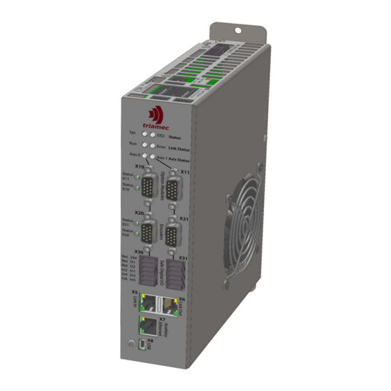
Page 27: Overview Of Drive Connections
7.3 Overview of Drive Connections Axis 1 Axis 0 Drive TSD80/TSD130 Switch/ Brake Feedback DigIn1 Switch DigIn2 DigIn3 DigIn4 Feedback DigIn5 DigIn6 Temp Brake P24V P24ret Motor DigOut1 DigOut2 Motor +24VDC 24VDC Ground Ground Isolation STO Ch1 Safety STO Ret STO Ch2 Safe In7 Aux 24V... - Page 28 The Ethernet connector can be connected to a TCP/IP Network. It’s possible to moni- AN123 tor and configure the drive within Triamec TAM-Explorer. In/Out The USB connector (mini-B) can be connected to a Microsoft® Windows® based notebook/PC. It’s possible to monitor and configure the drive within Triamec TAM- Explorer. X10/X11 In/Out Option modules...
-
Page 29: Electrical Supplies
7.4 Electrical supplies The power supply for the drive is separated into the supplies for logic and power sections. NOTICE The DC-Bus voltage can be switched on and off independently of the Logic Power. Standard operating procedure, however, is to power the logic before powering DC-Bus. 7.4.1 24V Logic supply (X2) The servo drive requires a 24VDC supply (PELV type sufficient) for its internal logic and for the... -
Page 30: Dc-Bus (X1)
Triamec power supplies TP80 and TP130. Please note if not using a Triamec power supply: The servo drives have no built in brake-resis - tor. When decelerating a mechanical load, currents can get negative, refer to chapter 5.4. -
Page 31: Safe Function Outputs (X3)
7.5 Safe Function Outputs (X3) The Safe Function Output connector X3 is found at the top side of the drive. The cable must be shorter than 20m. Use shielded cables if longer than 0.5m. Figure 11: Safe Function Outputs connector (X3). Pin Layout X3 Name Description... -
Page 32: Safe Torque Off Sto (X4)
7.6 Safe Torque Off STO (X4) The STO connector X4 is found at the top side of the drive. The cable must be shorter than 20m. Use shielded cables if longer than 0.5m. Figure 13: STO connector (X4). Pin Layout X4 Name Description STO Input Ch1... -
Page 33: Field-Bus Connection (X5, X6)
Beckhoff Automation and is now managed by the EtherCAT Technology Group (ETG). The drive must be connected to the EtherCAT PCI-Adapter card and the other Triamec devices in a chain topology starting with the Adapter card. The jacks (X5(Line In), X6(Line Out)) are not equivalent, the control flow has to be regarded. -
Page 34: Option Modules (X10, X11)
7.8 Option Modules (X10, X11) Two option module connectors access extended functions, if the corre- sponding option module is installed. Installation has to be done during production. Currently available functions are TOE1 An additional encoder input with the same specification as the built-in encoder (500kHz) ... -
Page 35: Feedback Systems (X20, X21)
7.9 Feedback Systems (X20, X21) Two encoder connectors are available by default (two more are available with option modules). They are located at the front side of the drive. X20 feeds axis 0. X21 feeds axis 1. Each connector supports various encoder types/protocols and some optional TTL inputs. -
Page 36: Analog Sin/Cos Encoder With Index
7.9.1 Analog Sin/Cos Encoder with Index Analog (Sin/Cos) encoder with index channel. Pin Layout X20/X21 Name Encoder +5VDC Encoder Supply 15-pin female ChA+ Channel A positive, Cosine 1Vpp D-Sub socket ChB+ Channel B positive, Sine 1Vpp ChZ+ Index channel positive, RS-422 input n.c. -
Page 37: Absolute Encoder With Sin/Cos Signals
7.9.2 Absolute Encoder with Sin/Cos signals Single-turn or Multi-turn analog (Sin/Cos) absolute encoder with a serial interface (EnDat 2.1/2.2, Biss-B, Biss-C) . This encoder type is operated as an analog Sin/Cos encoder. The absolute position (and some additional in- formation) is read during initialization using the digital serial interface. RS422 index channel is not available in this configuration. -
Page 38: Absolute Encoder Without Sin/Cos Signals
7.9.3 Absolute Encoder without Sin/Cos signals Single-turn or Multi-turn absolute encoder with a serial interface without analog sin/cos signals (Endat 2.2, Biss-B, Biss-C, Tamagawa, Nikon). Digital position information is transmitted at every position controller cycle digi- tally coded to the position controller. RS422 index channel is not available in this configuration. -
Page 39: Incremental Rs422 Encoder With Index
7.9.4 Incremental RS422 Encoder with Index Connecting an incremental encoder with index channel. Pin Layout X20/X21 Name Encoder +5VDC Encoder Supply 15-pin female ChA+ Channel A positive, RS-422 input D-Sub socket ChB+ Channel B positive, RS-422 input ChZ+ Index channel positive, RS-422 input n.c. -
Page 40: Incremental Ttl Encoder With Index
7.9.5 Incremental TTL Encoder with Index Connecting an incremental TTL encoder with index channel via EncIn0 and EncIn1. The source for position latch during homing can be cho- NOTICE sen between ChZ (RS-422) or EncIo2/3 in the software. Pin Layout X20/X21 Name Encoder +5VDC... -
Page 41: Digital Inputs And Outputs (X30+X31)
7.10 Digital inputs and outputs (X30+X31) The digital inputs and outputs are available at the front side of the drive. All inputs and outputs are galvanic isolated from the logic supply. The connectors X30 and X31 are not galvanically isolated to each other. X30 is assigned to axis 0, X31 is assigned to axis 1. -
Page 42: Digital Outputs
7.10.2 Digital Outputs The table below describes the pin out of the output pins, see chapter 5.2.1 for detailed specification of the output channels. The digital outputs are high-side switches and require an external supply between pin 1 and pin 2 for operation. The next chapter shows an example wiring for a motor-holding brake. Pin Layout X30/X31 Name Description... -
Page 43: Motor Connection (X40+X41)
7.11 Motor connection (X40+X41) This connector feeds the motor windings and an external temperature sensor. 7.11.1 Motor Power Connection The drive supports different motor configurations. All motor configurations use connectors at the bottom side of the drive. X40 is for axis 0 and X41 is for axis 1. The motor cable must be shielded. - Page 44 2-Phase AC Motor connection X40, X41 Figure 27: 2-phase motor connection. Pin Layout X40/X41 Name Description Maximum Current Cross-Section of Wire Protective earth Same or larger than UVW Motor phase P1 voltage 1.5mm min, 2.5mm 15 Arms Motor phase P voltage 1.5mm min, 2.5mm 15 Arms...
-
Page 45: Motor Temperature
7.11.2 Motor temperature A resistive motor temperature sensor which measures the temperature of the motor windings may be connected to X40 and X41, see chapter 5.2.1 for supported types and ranges. Use X40 for axis 0 and X41 for axis 1. Figure 29: Motor temperature connector. -
Page 46: Commissioning And Diagnostics
8 Commissioning and Diagnostics The following utilities are available for commissioning The TAM System Explorer software which is used for all commissioning and analysis work flows The setup guide [2]. The guides for the Beckhoff TwinCat Interfaces for Tria-Link drives ([3]) and for EtherCAT drives ([4]). Immediate state information is available through six bi-colored LEDs on the front side. - Page 47 Axis 0 is in error state (e.g., positionErrorLimit, over-current, ...) and axis 1 is operational System Status LED ~0.6s ~0.6s ~0.6s ~0.6s ~0.6s ~0.6s STO status LED Axis Status Axis 0 LED Axis Status Axis 1 LED STO state indications: STO Active state is indicated by a short single red blinking of the STO status LED System Status LED STO status LED...
-
Page 48: Appendix
All Triamec Motion AG products are warranted for a period of 12 months from the time of installa- tion, or 18 months from time of shipment, whichever comes first. No other warranties, expressed or implied –... -
Page 49: Revision History
Revision History Version Date Editor Comment 08/07/18 ab+up+mvx+lh First release for Revision 4, based on manual of HW Revisions 1..3 11/20/18 Correct DigIn naming, changed X7 Ethernet connector description 09/02/19 mvx+ab Commutation frequency limitation, TSD80-15, new peak current ratings,, Di- gIn spec.
Need help?
Do you have a question about the TSD85 Series and is the answer not in the manual?
Questions and answers