Table of Contents
Advertisement
Advertisement
Table of Contents

Related Manuals for Simphoenix DL100 Series

Summary of Contents for Simphoenix DL100 Series
- Page 2 Thanks for choosing the DL100 series universal low-power inverter produced by Shenzhen Sunfar Electric Technologies Co., Ltd. This Manual is the operating manual for DL100 series universal low-power inverters. It provides all relevant instructions and precautions for installation, wiring, functional parameters, daily care and maintenance, fault diagnosis and troubleshooting of DL100 series inverters.
-
Page 3: Table Of Contents
目 录 1 Product Introduction..................11 1.1 Description of inverter model................1.2 Model of inveter series..................1.3 Product appearance and name of components........... 1.4 Product technical indicators and specifications..........2 Inverter Installation....................2.1 Environmental requirements ................2.2 Installation dimension of inverters..............3 Inverter Wiring...................... - Page 4 6 Detailed Description of functions..............6.1 Basic operating parameter group..............6.2 Basic control parameter groups..............6.3 Motor parameter group..................6.4 Digital input and analog parameter group............. 6.5 Digital output and swing frequency operation parameter group....6.6 Multi-speed section and PLC operating parameter group......6.7 Communication setting parameter group............
- Page 5 Precautions Ⅰ Precautions DL100 series universal low-power inverters are applicable to general industrial single-phase and three-phase AC asynchronous motors. If this inverter is used for equipment which is failed and may cause personal injury (e.g. nuclear control system, aviation system, safety equipment and instruments), please take care and consult with the manufacturer;...
- Page 6 5. During installation, the frequency inverter shall be installed at the place able to bear its weight; otherwise, it may fall down or damage properties. The inverter shall not be dismantled or modified without authorization. DL100 Series Universal Low-Power Inverter...
- Page 7 4. When the altitude is over 1000m, the inverter shall be derated. Increase of altitude for every 1500 m shall be ground for derating by 10%. DL100 Series Universal Low-Power Inverter...
- Page 8 Waste gas from plastic burning: harmful and toxic gas may be produced during combustion of plastic and rubber products of the converter. Disposal: please dispose of inverters as industrial wastes. DL100 Series Universal Low-Power Inverter...
-
Page 9: Description Of Inverter Model
Three Phase 0075 Single Phase 1.2 Model of inverter series Rated output current Adaptive motor power Rated capacity Inverter model (KW) (KVA) DL100-2S0004(B) DL100-2S0007(B) 0.75 DL100-2S0015(B) DL100-2S0022(B) 10.0 DL100-4T0007(B) 0.75 DL100-4T0015(B) DL100-4T0022(B) DL100-4T0040(B) DL100-4T0055(B) DL100-4T0075(B) 11.2 DL100 Series Universal Low-Power Inverter... -
Page 10: Product Appearance And Name Of Components
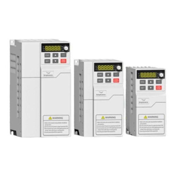
Main circuit terminal Fan assembly Fan assembly Figure 1-3 Appearance and Component Figure 1-2 Appearance and Component Name of Category II Inverters Name of Category III Inverters Applicable models: Applicable models: DL100-2S0022(B) DL100-2S0007(B)~DL100-2S0015(B) DL100-4T0007(B)~DL100-4T0015(B) DL100-4T0022(B)~DL100-4T0075(B) DL100 Series Universal Low-Power Inverter... -
Page 11: Product Technical Indicators And Specifications
Analog DC voltage 0-10V, and DC current 0-20mA (optional) input Frequency setting Operating panel setting, potentiometer setting, RS485 port setting, Digital UP/DW terminal control, and multiple combined setting with input analog input. DL100 Series Universal Low-Power Inverter... - Page 12 0~1000m, the load is derated by 10% for each kilometer increase. Protecting IP20 grade Forced air cooling Cooling mode (Model 2S0004 is natural air cooling without fan) wall-mounted Installation mode (Model 2S0004 must be mounted vertically on the wall) Vibration <6m/s² DL100 Series Universal Low-Power Inverter...
-
Page 13: Inverter Installation
6. The inverter should be away from electromagnetic interference sources. 7. If there is too much dust in the environment, please close the cooling hole.(As show in figure 2-1-A) Closed position of heat dissipation hole Figure 2-1-A DL100 Series Universal Low-Power Inverter... -
Page 14: Installation Dimension Of Inverters
4.Securely ground(earth) the equipment. 变 频 器 Figure 2-1-B Installation Spacing Distance Figure 2-1-C Installation of Multiple Inverters 2.2 Installation dimension of inverters Category I and II inverters Category III inverters DL100-2S0004(B) DL100-2S0015(B) DL100-2S0022(B) DL100-4T0007(B) DL100-4T0015(B) DL100-4T0022(B) DL100-4T0075(B) DL100 Series Universal Low-Power Inverter... - Page 15 Inverter Installation 7 The specific installation dimensions of DL100 series inverters are shown infollowing table: Inverter model Inverter model Screw (three-phase 380V) (single-phase 220V) specification DL100-2S0004(B) DL100-4T0007(B) DL100-2S0007(B) DL100-4T0015(B) DL100-2S0015(B) DL100-4T0022(B) DL100-2S0022(B) DL100-4T0040(B) DL100-4T0055(B) DL100-4T0075(B) DL100 Series Universal Low-Power Inverter...
-
Page 16: Inverter Wiring
U, V and W output end of the frequency inverter, as shown in figure 3-1. Motor 电 动 机 Inverter 变 频 器 RC absorber 阻 容 吸 收 装 置 Figure 3-1 Forbidding connecting a RC absorber at the output terminal DL100 Series Universal Low-Power Inverter... -
Page 17: Wiring Of Peripheral Elements
3) Weaken influenced caused by unbalanced voltage of three-phase power supply. Brake resistance When the motor is at the dynamic braking status, it can avoid producing over high pumping voltage in the DC loop. DL100 Series Universal Low-Power Inverter... - Page 18 0.3~0.4 E0.75-6 terminal Wire ear model W(mm) F(mm) L(mm) H(mm) d1(mm) D(mm) T(mm) PVT1.25-9 PVT2-9 PVT/E PVT5.5-13 series E0.5-6 E0.75-6 12.3 Wire ear model d2(mm) W(mm) F(mm) L(mm) H(mm) d1(mm) D(mm) T(mm) 22.5 5.5-4S series DL100 Series Universal Low-Power Inverter...
-
Page 19: Product Introduction
Failure alarm output 故障报警输出 Programmable 可编程输入端子 input terminal To braking resistor 外接制动电阻 Auxiliary DC power supply 辅助直流电源 Voltmeter 电压表(0~10V) (0-10V) Open-circuit collector output OC 开路集电极输出 0~10V (0~20mA) Frequency setting 频率设定 Figure 3-3 Basic Wiring of Inverter DL100 Series Universal Low-Power Inverter... -
Page 20: Wiring Of Main Loop Terminal
DC side voltage positive terminal Braking resistor can be connected between PP and PB To grid three-phase AC 380V R、S、T Electric power supply Three-phase Braking The earth motor power input resistor To three-phase AC 380V motor U、V、W Earthing terminal DL100 Series Universal Low-Power Inverter... -
Page 21: Wiring Of Control Loop Terminal
L, the terminal and CM Multifunctional input terminal 4 are closed and effective, and when the switch is to H, the terminal is connected to 24V End closure effective. DL100 Series Universal Low-Power Inverter... - Page 22 AC 250V, 1A resistive load , Programm- TA/TC TA-TC function is set by able output parameter [F4.01]. Convenient communication interface uses special cable (optional) to Communi- RS+/RS- 485 communication port copy/download cation parameters conveniently through 485 communication. DL100 Series Universal Low-Power Inverter...
-
Page 23: Operating Panel
Shift key. When modifying data with any data modification key, press this key to select the data digit to be modified, and the selected digit will flash. DL100 Series Universal Low-Power Inverter... -
Page 24: Panel Operating Method
Status parameter inquiry Disply:d0-00 Monitoring code Select inquired status parameter Status parameter inquiry Disply:d0-02 Function code Determine inquiry status Return parameter Display:383 Output voltage Parameter inquiry Enter parameter modification mode (see next section) Parameter modification mode Display:F0.00 function code DL100 Series Universal Low-Power Inverter... - Page 25 Parameter inquiry Display:F0.00 Function code Select inquired/modified parameteritem Display:F0.01 Function code Parameter inquiry Display:45.0 Parameter data Parameter inquiry Modify parameter when necessar Parameter modification Display:50.0 Parameter data Save modified paramete Parameter save Display:F0.01 Function code DL100 Series Universal Low-Power Inverter...
-
Page 26: List Of Status Monitoring Parameters
(2) Selection of running command input channel ([F0.06]) The inverter’s initial setting varies according to different models. When this parameter is set to [F0.06] =###0, the inverter’s start and stop control will be DL100 Series Universal Low-Power Inverter... -
Page 27: Simple Running
The default value of the carrier frequency is fixed (2-8 KHz). If the motor is completely empty-load, slight oscillation may occur sometimes in the operation under high carrier frequency. At this time, please reduce the setting value of the carrier frequency. (Parameter [F0.08]). DL100 Series Universal Low-Power Inverter... -
Page 28: Function Parameter Table
9: Only allow to protection modify this parameter Other values: all parameters are allowed to be rewritten Upper limit F0.03 5.00~600.00 0.01 50.00 frequency Lower limit F0.04 0.00~[F0.03] 0.01 0.00 frequency Lower limit F0.05 frequency operation mode DL100 Series Universal Low-Power Inverter... - Page 29 Jog acceleration F0.16 0.01 ~ 600.00 Sec 0.01 5.00 time Jog deceleration F0.17 0.01 ~ 600.00 Sec 0.01 5.00 time Forward jog F0.18 0.00~[F0.03] 0.01 5.00 frequency Reverse jog F0.19 0.00~[F0.03] 0.01 5.00 frequency DL100 Series Universal Low-Power Inverter...
- Page 30 Fault F1.19 self-recovery 0.00~600.00 0.01 1.00 time Fundamental F2.00 5.00~600.00 0.01 50.00 frequency Maximum F2.01 25 ~250V/50 ~ 500V 220/380 output voltage F2.02 Torque boost 0.0~20.0% F2.03 V/F frequency 1 0.00~[F2.00] 0.01 0.00 DL100 Series Universal Low-Power Inverter...
- Page 31 0.01 0.00 limit voltage AI input upper F3.10 [F3.19]~10.00 0.01 10.00 limit voltage AI input filter F3.11 0~200 time Minimum set F3.12 0.00~[F3.13] 0.01 0.00 frequency Maximum set F3.13 [F3.12]~[F0.03] 0.01 50.00 frequency F3.14 Reserve DL100 Series Universal Low-Power Inverter...
- Page 32 Multi-speed 0.00Hz ~ upper F5.01 0.01 35.00 frequency 1 limit frequency Multi-speed 0.00Hz ~ upper F5.02 0.01 15.00 frequency 2 limit frequency Multi-speed 0.00Hz ~ upper F5.03 0.01 3.00 frequency 3 limit frequency DL100 Series Universal Low-Power Inverter...
- Page 33 Overtime F6.04 0.1~20.0 0.1s checkout time Communication F6.05 disconnection action selection Communication F6.06 0.100~10.000 0.001 1.000 setting factor F6.07 Reserve Permission F6.08 0~60000 password Program F6.09 1100~1199 1100 Version Monitoring F6.10 parameter 0~20 selection DL100 Series Universal Low-Power Inverter...
- Page 34 PID adjustment F7.11 0.0~100.0% 100.0 frequency range Broken wire F7.12 0.0~50.0% detection Disconnection F7.13 detection time 0.01~60.00 0.01 5.00 judgment F7.14 Static deviation 0.0~10.0% F7.15 Reserve F7.16 Reserve F7.17 Reserve F7.18 Reserve F7.19 Reserve DL100 Series Universal Low-Power Inverter...
-
Page 35: Detailed Description Of Functions
When the frequency input channel selects the digital setting ([F0.00] = 0), the output frequency of the inverter is determined by this value. When the operation panel is in the normal monitoring mode, you can directly press the key to modify this parameter. DL100 Series Universal Low-Power Inverter... - Page 36 Increase the set frequency. When the set frequency is higher than the lower limit frequency, the inverter will run at the set frequency. Its function is shown in Figure 6-1: DL100 Series Universal Low-Power Inverter...
- Page 37 The running command of the inverter receives commands from the upper computer or host computer through the serial interface. This mode should also be selected when the machine is set as a slave in the linkage control. DL100 Series Universal Low-Power Inverter...
- Page 38 The switch function description is as follows: 1. SW1(Three-wire operation control terminal) —— Inverter stop trigger switch 2. SW2(FWD) —— Forward trigger switch 3. SW3(REV) —— Reverse trigger switch igure 6-2 Wiring diagram of three-wire control mode DL100 Series Universal Low-Power Inverter...
- Page 39 When the ambient temperature is high, the motor load is heavy, or the inverter fails due to the above reasons, the carrier DL100 Series Universal Low-Power Inverter...
- Page 40 The set frequency of the inverter is determined by the linear combination of multiple frequency input channels. The set combination mode is shown in the table below. Through the combination setting, multiple channels can jointly control the frequency output of the inverter. DL100 Series Universal Low-Power Inverter...
- Page 41 F0.17 Jog deceleration time Predetermined area : 0.01 ~600.00Sec The transition acceleration and deceleration time between the initial running frequency and the jog frequency. F0.18 Forward jog frequency Predetermined area : 0.00Hz ~[F0.03] F0.19 Reverse jog frequency Predetermined area : 0.00Hz~[F0.03] DL100 Series Universal Low-Power Inverter...
-
Page 42: Basic Control Parameter Groups
When stopping, the inverter will gradually reduce its output frequency to zero according to the set deceleration time and then stop. 1: Free stop When stopping, the inverter outputs zero frequency, blocks the output signal, DL100 Series Universal Low-Power Inverter... - Page 43 ([F1.08]), the built-in braking unit of the inverter is turned off, as shown in Figure 6-5. DC side voltage [F2.08] Braking unit action Time Figure 6-5 Dynamic braking DL100 Series Universal Low-Power Inverter...
- Page 44 As shown in Figure 6-6. Frequency Deceleration time adjustment Time DC voltage [F1.12] Time Figure 6-6 Voltage stall protection during deceleration DL100 Series Universal Low-Power Inverter...
- Page 45 (acceleration, deceleration, steady state operation), when the output current of the inverter exceeds the value specified in this parameter, the inverter will adjust the output frequency to limit the current within the specified range to avoid over-current tripping. DL100 Series Universal Low-Power Inverter...
-
Page 46: Motor Parameter Group
Maximum output voltage Predetermined area : 25 ~ 250V/50 ~ 500V The basic operating frequency is the minimum frequency corresponding to the maximum output voltage of the inverter, generally the rated frequency of the motor. DL100 Series Universal Low-Power Inverter... - Page 47 Figure 6-8. [F2.02] × Boost voltage [F2.01] Voltage [F2.01] [F2.02] Boost voltage Frequency [F2.00] Figure 6-8 Schematic diagram of torque boost DL100 Series Universal Low-Power Inverter...
- Page 48 0:invalid 1:invalid deceleration 2:efficient F2.12 Number of motor pole pairs Predetermined area:1~16 This parameter is mainly used for the calculation of motor speed. DL100 Series Universal Low-Power Inverter...
-
Page 49: Digital Input And Analog Parameter Group
1: Multi-speed control 1 2: Multi-speed control 2 3: Multi-speed control 3 The combination of the multi-speed control terminal is used to select the output frequency of the multi-speed, and the specific frequency setting of each stage is DL100 Series Universal Low-Power Inverter... - Page 50 When the terminal set by this parameter is closed, it indicates that the external equipment has a disconnection fault. At this time, for the safety of the equipment, the inverter will block the output and display the external fault signal Fu.17 at the DL100 Series Universal Low-Power Inverter...
- Page 51 F3.12 Minimum set frequency Predetermined area : 0.00Hz ~ [F3.13] F3.13 Maximum set frequency Predetermined area : [F3.12] ~ [F0.03] The corresponding relationship between the analog input AI and set frequency is shown in the figure 6-10. DL100 Series Universal Low-Power Inverter...
- Page 52 F3.17 AO output lower limit Predetermined area : 0.00 V ~ [F3.18] F3.18 AO output upper limit Predetermined area : [F3.17] ~ 10.00 V Define the maximum and minimum values of the analog output AO output signal. As shown in Figure 6-11: DL100 Series Universal Low-Power Inverter...
-
Page 53: Digital Output And Swing Frequency Operation Parameter Group
Relay contact output: When the set output function is valid, the normally open contact TA-TC is turned on. Figure 6-12 Internal wiring of OC output terminal DL100 Series Universal Low-Power Inverter... - Page 54 When the output frequency of the inverter is lower than the FDT frequency level, the invalid signal will be output after the same delay time. DL100 Series Universal Low-Power Inverter...
- Page 55 Figure 6-15 Overload alarm 4: Frequency reaches the upper limit When the output frequency of the inverter reaches the upper limit frequency, this port outputs a valid signal, otherwise it outputs an invalid signal. DL100 Series Universal Low-Power Inverter...
- Page 56 Predetermined area : 0.00 ~ [F0.03] It is used to set the frequency defined by the output terminal to reach the detection range. When the output frequency of the inverter is within the positive or DL100 Series Universal Low-Power Inverter...
- Page 57 [F3.01] ~ [F3.04]), it runs in the swing frequency mode. LED ten digits: center frequency setting 0:Digital setting, set by [F4.15] 1:Frequency channel selection, given by frequency channel DL100 Series Universal Low-Power Inverter...
- Page 58 The triangular wave rise time is the running time from the lower limit frequency of the swing frequency to the upper limit frequency of the swing frequency during swing frequency operation, that is, the acceleration time in the swing frequency operation cycle. DL100 Series Universal Low-Power Inverter...
-
Page 59: Multi-Speed Section And Plc Operating Parameter Group
The other processes are the same as mode 1. 4: Continuous loop mode The basic operation mode is the same as that of mode 0. After one cycle of DL100 Series Universal Low-Power Inverter... - Page 60 Note: The running time of each stage refers to the time from the end of the previous stage to the end of the current stage, including the acceleration or deceleration time from running to the frequency of the current stage. DL100 Series Universal Low-Power Inverter...
- Page 61 When the operation is resumed, the stop command should be given first, and then the start command should be given. When this parameter is set to 0, the timer running stop function is invalid. DL100 Series Universal Low-Power Inverter...
-
Page 62: Communication Setting Parameter Group
F6.03 Linkage settings Predetermined area : 0000 ~ 0011 When using the linkage function, the master is set to 0011 and the slave is set to 0000 to realize linkage communication. DL100 Series Universal Low-Power Inverter... - Page 63 Predetermined area : 0 ~ 60000 This parameter is a check code value to obtain certain internal parameter query and modification permissions. F6.09 Program Version Predetermined area : 1100 ~ 1199 Inverter control software version number, read-only parameter. DL100 Series Universal Low-Power Inverter...
-
Page 64: Pid Parameter Group
The schematic diagram is shown in Figure 6-17. Target value Ti S Controlled Td*S+1 sustem Feedbak value Figure 6-17 PID function diagram DL100 Series Universal Low-Power Inverter... - Page 65 1~100:The feedforward action coefficient can increase the response speed when the system is started. F7.06 Reserve F7.07 Proportional gain Predetermined area : 0.01~10.00 F7.08 Integration time Predetermined area : 0.01~10.00 Sec This parameter group is the built-in PID controller parameter. DL100 Series Universal Low-Power Inverter...
- Page 66 After the delay time, the system is still in the disconnection state, and it is considered that a disconnection fault has occurred. F7.14 Static deviation range Predetermined area : 0 ~10.0% When the error is within this range, PID will not adjust. DL100 Series Universal Low-Power Inverter...
-
Page 67: Fault Diagnosis And Countermeasures
4. The network voltage is 4. Check the network voltage. too low. 1. The load is too large. 1. Reduce load. Fu.13 Motor overload 2. The acceleration time is 2. Extend the acceleration time. DL100 Series Universal Low-Power Inverter... -
Page 68: Fault Record Query
The output current of the last d-25 fault recently The fault information and condition monitoring parameters are stored in a unified manner; please refer to the keyboard operation method to query information. DL100 Series Universal Low-Power Inverter... -
Page 69: Fault Reset
Method II: Disconnect after closure of external multi-function terminals X1~X4 (fault reset) and CM. Method III: Send the fault reset command via RS485 interface. Method IV: Cut off power supply. DL100 Series Universal Low-Power Inverter... -
Page 70: Appendixⅰ: Modbus Protocol Specification
Data length(Byte) 2*Number of registers (2) Function code 06: Rewrite operation command, running frequency and functional parameter of single inverter. Sent by main machine: Register initial address Register data PDU PART High High Data length(Byte) DL100 Series Universal Low-Power Inverter... - Page 71 Illegal function code Illegal data address Overhanging data Invalid operation of slave machine Too much read-write parameters Reserve read-write, implicit parameter Slave machine running forbids modifying data Data modification is protected by password Failure in read-write parameter DL100 Series Universal Low-Power Inverter...
- Page 72 “F” to “0” in the high address of the register, e.g. when writing the RAM value of F1.11, its register address should be 010 B, but the expression method of the register address cannot be used to read the functional parameters of the frequency inverter. DL100 Series Universal Low-Power Inverter...
- Page 73 (1). Start 1# inverter in FWD running condition Main machine request: Slave Register initial address Register data CRC CHECK Function machine code High High High address Slave machine response: inverter in FWD running condition responds the same data with main machine request. DL100 Series Universal Low-Power Inverter...
- Page 74 High Low High Low High Low High Low Low High Slave machine response: Slave Register initial address Number of registers CRC CHECK Function machine code High High High address DL100 Series Universal Low-Power Inverter...
-
Page 75: Appendixⅱ: Brake Resistor Selection
The brake resistance power is the estimated value in working condition of brake resistance interval; when continuous working time of brake resistance is longer (more than 5s), it’s necessary to properly increase power class of brake resistance under the condition of same resistance value. DL100 Series Universal Low-Power Inverter... - Page 77 1. Please keep this card properly, please contact service center with this card and invoice when need maintenance. 2. The warranty period is 18 months. Shenzhen Simphoenix Electric Technology Co.,Ltd Cut along the dotted line ------------------------------------------------------- ------------------------------------------------------------ Certificate of Approval...
Need help?
Do you have a question about the DL100 Series and is the answer not in the manual?
Questions and answers