Advertisement
Available languages
Available languages
Quick Links
8252335COM
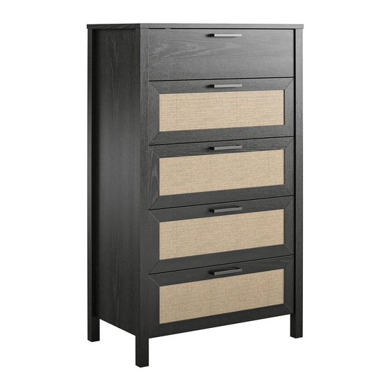
5 Drawer Dresser
Date of Purchase ___ / ___ / ___
Lot Number:
THIS INSTRUCTION BOOKLET CONTAINS IMPORTANT SAFETY INFORMATION. PLEASE READ AND KEEP FOR FUTURE REFERENCE.
Keep your home and family safe
with the wall anchor kit that is
included with the product.
Serious or fatal crushing injuries can
occur from tipping furniture.
WARNING: Manufacturer assumes no liability
for improper installation or excessive loads
placed on screws or bracket. This wall anchor
is not a substitute for proper adult supervision.
Do Not Return This Product!
Contact our customer service team for help first.
Call: 1-800-489-3351 (toll free)
Monday-Friday 9am - 5pm CST
Visit: www.ameriwoodhome.com
Easy
Assembly Difficulty Meter
B348252335COM0
Tough
Advertisement

Subscribe to Our Youtube Channel
Related Manuals for Queer Eye 8252335COM


Summary of Contents for Queer Eye 8252335COM
- Page 1 8252335COM 5 Drawer Dresser B348252335COM0 Date of Purchase ___ / ___ / ___ Lot Number: Do Not Return This Product! Contact our customer service team for help first. Call: 1-800-489-3351 (toll free) Monday-Friday 9am - 5pm CST Visit: www.ameriwoodhome.com THIS INSTRUCTION BOOKLET CONTAINS IMPORTANT SAFETY INFORMATION. PLEASE READ AND KEEP FOR FUTURE REFERENCE.
-
Page 2: Helpful Hints
Contact Us! Do NOT return this product! Contact our friendly customer service team first for help. Assembly Tips Call us! 1-800-489-3351 Monday-Friday 9am - 5pm CST Tube Visit ameriwoodhome.com to view the limited warranty valid in the U.S. and Canada. Helpful Hints PEOPLE NEEDED FOR ASSEMBLY: 1-2 ESTIMATED ASSEMBLY TIME: 2 HOURS... -
Page 3: Before You Start
Before You Start Read through each step carefully and follow the proper order Separate and count all your parts and hardware Give yourself enough room for the assembly process Have the following tools: Flat Head Screwdriver, #2 Phillips Head Screwdriver and Hammer Caution: If using a power drill or power screwdriver for screwing, please be aware to slow down and stop when screw is tight. - Page 4 Before You Start Please Note: You may need to lightly tap the wood dowels to insert into the holes during your assembly process. wood dowel...
-
Page 5: Board Identification
Board Identification Not actual size Right Panel Left Panel 38252335020 38252335030 38252335010 Bottom Support Right Front Leg Left Front Leg 38252335040 38252335050 38252335060 38252335070 Right Rear Leg Upper Drawer Front Left Rear Leg 38252335100 38252335080 38252335090 SIDE BACK Drawer Side (x10) Drawer Bottom (x5) Drawer Front (x4) Drawer Back (x5) - Page 6 Board Identification Not actual size This piece is paperboard construction. It is not made from wood, but is required for the assembly of your unit. Back Panel K825200000 SIDE BACK SIDE SIDE BACK SIDE...
-
Page 7: Part List
Part List Actual Size (x10) (x10) (x12) (x20) (x68) #A22620 #A21970 #A22610 #A21110 #A12120 cam lock cam bolt drive fastener nail #8 x 7/16" screw (x50) (x12) (x18) (x10) (x12) #A11080 #A22910 #A21660 #A17400 #A22920 #6 x 7/16" screw connector bolt wood dowel 8-32 x 7/8"... - Page 8 Part List Not Actual Size Left Cabinet Member Right Cabinet Member Left Drawer Member Right Drawer Member (x1) (x10) (x5) #A84050 #A54520 #A56750 safety bracket kit drawer bracket drawer slide pkg. (x5) (x5) #A54900 #A51715 drawer brace handle...
- Page 9 STEP 1 (x12) #A22910...
- Page 10 STEP 2 (x2) (x3) (x6) (x6) #A22620 #A22610 #A21670 #A22920 Quick Assembly You will need to tap the connector (9) with a hammer to fully insert. Be sure the connector is positioned as shown before tapping into hole. Proper orientation of CAM LOCK...
- Page 11 STEP 3 end view Turn screw clockwise to lock in place.
- Page 12 STEP 4 Marked with a "L" Left Cabinet Member (x15) (x5) #A11080 #A56750 10 10...
- Page 13 STEP 5 (x2) (x3) (x6) (x6) #A22620 #A22610 #A21670 #A22920 Quick Assembly You will need to tap the connector (9) with a hammer to fully insert. Be sure the connector is positioned as shown Proper orientation of CAM LOCK before tapping into hole.
- Page 14 STEP 6 Turn screw clockwise end view to lock in place.
- Page 15 STEP 7 marked with a "R" Right Cabinet Member (x15) (x5) #A11080 #A56750...
- Page 16 STEP 8 Quick Assembly (x6) (x6) #A21660 #A22620 Proper orientation of CAM LOCK...
- Page 17 STEP 9 finished edge...
- Page 18 STEP 10...
- Page 19 STEP 11 (x4) (x1) #A22610 #A84050 Do not fully tighten screw.
- Page 20 STEP 12 finished edge...
- Page 21 STEP 13 (x12) (x18) #A21110 #A12120 IMPORTANT! THE BACK PANEL IS A STRUCTURAL PART OF THIS UNIT AND MUST BE INSTALLED PROPERLY. With the help of another person, turn the unit over on its front side. Position back panel as shown. Align squarely with outer edges.
- Page 22 STEP 14 For Masonry, Concrete, or other wall materials: Consult your local hardware store for appropriate anchors to securely attach the safety bracket. (x1) #A84050 IMPORTANT: THIS UNIT MUST BE SECURE TO THE WALL TO HELP PREVENT TIPOVER. FOLLOW THESE INSTRUCTIONS TO INSTALL THE ANTI-TIPPING SAFETY BRACKET PROVIDED WITH THIS PRODUCT.
- Page 23 STEP 15 (x20) (x10) #A12120 #A54520 SIDE SIDE Side View Side View...
- Page 24 STEP 16 Note: This view shows the set-up for the bottom four drawers (drawer fronts K). For the top drawer (drawer front J), it's the same process. (x20) #A12120 Be sure the grooves in the drawer sides are centered with the groove in the drawer fronts.
- Page 25 STEP 17 SIDE finished surface SIDE...
- Page 26 STEP 18 Note: You will need to tap the drive fasteners (xx) with a hammer to securely fasten. (x20) #A21970 BACK SIDE SIDE...
- Page 27 STEP 19 (x5) (x10) #A54900 #A12120 BACK...
- Page 28 STEP 20 Left Drawer Member Right Drawer Member (x5) (x20) (x10) #A56750 #A11080 #A17400 Attach the slides first and then the handles. (x5) #A51715 BACK SIDE SIDE...
- Page 29 STEP 21 Note: The drawer bracket holes are slotted. Drawer fronts can be adjusted by loosening screws, making needed adjustments and retightening screws. roller cabinet member drawer runner roller...
- Page 30 Maximum Loads This unit has been designed to support the maximum loads shown. Exceeding these load limits could cause sagging, instability, product collapse, and/or serious injury. 35 lbs 15.8 kg 50 lbs (each drawer) 22.6 kg Warning: Risk of injury to persons - do not place a television on this furniture. This furniture is not approved for use with a television.
- Page 31 Register your product to receive the following: * New trend details - sneak peek on what's new * Surveys - have a voice within our community * Exclusive deals and discount codes * Quick and easy replacement part service To register your product, visit ameriwoodhome.com Visit your local retailer's website, rate your purchased product and leave us some feedback! We would like to extend a big "Thank You"...
- Page 32 Español Cubierta Delantera Este libro de instrucciones contiene información IMPORTANTE de seguridad. Por favor lea y manténgalo para referencia en el futuro. No Regrese este producto! Comuniquese con nuestro amistoso equipo de servicio al cliente para obtener ayuda. Llamenos al: 1-800-489-3351 (Gratis) Lunes - Viernes 9am - 5pm CST Visitar: www.ameriwoodhome.com PRECAUCION Este mueble puede volcarse y causar graves heridas y/o muerte.
- Page 33 Español Página 10 / 13 Deberá golpear suavemente el conector (9) con un martillo para insertarlo por completo. Asegúrese de que el conector está posicionado como se muestra antes de colocarlo en el agujero. Página 21 ¡IMPORTANTE! EL PANEL TRASERO ES UNA PARTE ESTRUCTURAL DE ESTA UNIDAD Y DEBE INSTALARSE ADECUADAMENTE.
- Page 34 Español Página 24 Nota: Esta vista muestra la disposición para los cuatro cajones inferiores (frentes de cajón K). Para el cajón superior (frente de cajón J), es el mismo proceso. Asegúrese de que las ranuras a los costados de los cajones estén centradas con las ranuras de los frentes de los cajones.
- Page 35 Français Couverture Avant CE LIVRET D'INSTRUCTION CONTIENT DES INFORMATIONS IMPORTANTES SUR LA SÉCURITÉ. VEUILLEZ LIRE ET GARDER POUR UNE RÉFÉRENCE FUTURE Ne retournez pas ce produit! Contactez notre équipe de service à la clientèle amicale d'abord pour obtenir de l'aide. Appelez-nous: 1-800-489-3351 (sans frais) du Lundi au Vendredi de 9h à...
- Page 36 Français Page 10 / 13 Vous devrez taper sur le connecteur (9) avec un marteau pour l'insérer complètement. Assurez-vous que le connecteur est positionné comme indiqué avant de le taper dans le trou. Page 21 IMPORTANT! LE PANNEAU ARRIÈRE EST UNE PARTIE STRUCTURELLE DE CETTE UNITÉ ET DOIT ÊTRE INSTALLÉ...
- Page 37 Français Page 24 Note : Cette vue montre la disposition des quatre tiroirs du bas (façades de tiroirs K). Pour le tiroir du haut (façade de tiroir J), c'est le même processus. Assurez-vous que les rainures des côtés des tiroirs sont centrées avec la rainure des façades des tiroirs. Page 26 Note : Vous devrez taper sur les attaches de fixation (xx) avec un marteau pour les fixer solidement.
Need help?
Do you have a question about the 8252335COM and is the answer not in the manual?
Questions and answers