Table of Contents
Advertisement
Advertisement
Table of Contents

Related Manuals for Felder Hammer HNC3 825


Summary of Contents for Felder Hammer HNC3 825
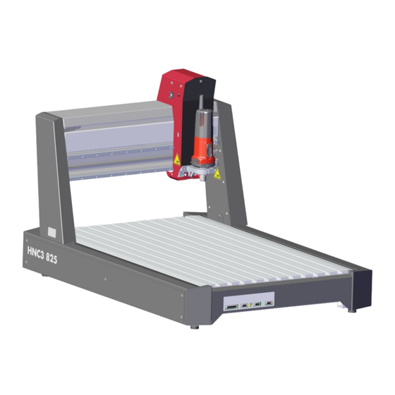
- Page 1 HNC3 825 / HNC3 825 perform CNC Machining Centre Keep this manual to hand and in good condition for future reference! Please read this operating manual carefully before using the machine! Translation of the original operating instructions Operating instructions 500034-900A, 2, en_GB...
- Page 2 FELDER KG KR-Felder-Straße 1,A-6060 HALL in Tirol, AUSTRIA Telephone: +43 5223 5850 0 Email: info@felder-group.com Internet: www.felder-group.com © 2022...
-
Page 3: Table Of Contents
HNC3 825 / HNC3 825 perform Table of contents Table of contents Information about the manual..........Symbol legend. - Page 4 Table of contents Setup and installation............Unpack machine.
-
Page 5: Information About The Manual
HNC3 825 / HNC3 825 perform Information about the manual Information about the manual Symbol legend Safety instructions Safety instructions in this manual are indicated with symbols. The safety instruc- tions are introduced by key words which state in words the extent of the hazard. Comply with safety instructions under all circumstances, and act with care in order to avoid accidents, personal injury, or material damage. -
Page 6: Contents Of The Operating Manual
We reserve the right to make technical changes to the product in order to improve the properties of use and further product development. ● The guarantee period is in accordance with national guidelines. Details may be found on our website, www.felder-group.com. ● Should any questions arise, please contact the manufacturer. Copyright ●... -
Page 7: Training
HNC3 825 / HNC3 825 perform Information about the manual Training ● All those appointed to work on or with the machine must have fully read and understood the manual before commencing any work. This requirement must be met even if the appointed person is familiar with the operation of such a machine or a similar one, or has been trained by the manufacturer. -
Page 8: Safety Instructions
Safety instructions Safety instructions Intended use ● The machine described in this manual is intended solely for the processing of wood, synthetic materials, and similar machinable materials. Operational safety is only guaranteed when the machine is used for the intended pur- poses. -
Page 9: Making Changes And Modifications To The Machine
HNC3 825 / HNC3 825 perform Safety instructions ● If the personnel lack the necessary knowledge for working on or with the machine, they must be trained. Responsibility for working with the machine (installation, service, maintenance, overhaul) must be clearly defined and strictly observed. -
Page 10: Prohibitions
Safety instructions 2.6.1 Prohibitions It is forbidden to wear loose clothing, wide sleeves, too long and wide trousers, shirts etc. when working with the machine. It is forbidden to wear belts, scarves, ribbons, back straps, necklaces, bracelets, open long hair without a hairnet etc. when working with the machine. -
Page 11: Other Risks
HNC3 825 / HNC3 825 perform Safety instructions Note Ear protection: Protection from noise emissions by the machine. Other risks The machine has undergone a hazard analysis. The design and construction of the machine are based on the results of this analysis and correspond to state-of- the-art technology. - Page 12 Safety instructions Disorder at the workplace Loose objects or objects that are lying around can cause severe injuries. ● Ensure that there is sufficient space to work around the machine. ● Remove loose objects from the working area. ● Keep the work area orderly and clean. Insufficient lighting of the installation room Serious injuries ●...
-
Page 13: Transport, Setup, Installation And Disposal
HNC3 825 / HNC3 825 perform Safety instructions 2.7.1 Transport, setup, installation and disposal Improper transport Improper transport can cause the machine to tilt or fall. This can cause severe crushing. ● Carry out transport according to the specifications in this instruction. ●... -
Page 14: Operate, Maintain And Troubleshoot
As part of the machine maintenance, the whole machine, including the safety devices, must be checked regularly for damage. Improper replacement or reparation of safety devices with safety function Serious injuries ● Only let safety devices be replaced or repaired by expert personnel of the Felder Group. -
Page 15: Foreseeable Misuses
HNC3 825 / HNC3 825 perform Safety instructions Dust deposits Dust build-ups can ignite when in contact with hot parts or cause an explosive atmosphere due to resuspension. Fire or explosion events can cause serious inju- ries. ● Clean production area as needed. ●... - Page 16 Safety instructions Maintenance misapplication: ● Service work carried out by untrained or unauthorised personnel. ● Non-observance of the maintenance guidelines. ● Non-observance of usage and damage tracks.
-
Page 17: Declaration Of Conformity
The signatory of this statement is the appointed agent for the compilation of the technical information. Prof. h.c. Ing. Johann Georg Felder CEO Felder KG KR-Felder-Straße 1, A-6060 HALL in Tirol... - Page 18 The signatory of this statement is the appointed agent for the compilation of the technical information. Prof. h.c. Ing. Johann Georg Felder CEO Felder KG KR-Felder-Straße 1, A-6060 HALL in Tirol...
-
Page 19: Technical Information
HNC3 825 / HNC3 825 perform Technical information Technical information Technical information All technical information is for the standard equipment without spindle and extrac- tion hood. Machine Data Value Unit Total length 1111 mm Total width 766 mm Total height 685 mm HNC3 825 weight approx. - Page 20 Technical information Data Value Unit X-axis 825 mm Y-axis 479 mm Z-axis 160 mm Additional technical information Data Value Unit Portal clearance width 625 mm Portal clearance height 160 mm Table surface 1005 x 574 mm T grooves in the table for M6 17.5 x 7.5 mm Drive spindle Z axis trapezoidal 14 x 6 mm...
- Page 21 HNC3 825 / HNC3 825 perform Technical information Reference point Fig. 2: Reference point X-axis Y-axis Machine zero point Reference point Front of the machine The machine zero point is situated at the rear, left hand corner (Rear: Main switch, power connection). X-axis Y-axis Z-axis...
-
Page 22: Tools
Technical information Data Value Unit Technical resolution in 1/8 step mode 0.00375 mm Z axis Repeatability ± 0.05 mm Backlash X- / Y-axis ≤ 0.02 mm Backlash Z-axis ≤ 0.1 mm Torsional stiffness (150 N) 0.1 mm Machine accuracy In order to achieve these levels of accuracy, all of the technolog- ical parameters need to be correctly selected. -
Page 23: Operation And Storage Conditions
HNC3 825 / HNC3 825 perform Technical information Data Value Unit Ø tool max. 36 mm Ø tool shaft max. HFM 1000 PV-WS 8 mm Ø tool shaft max. HFM 1000 PV-ER 10 mm Ø tool shaft max. HNC3 825 perform 16 mm ●... -
Page 24: Electrical Connection
Technical information Electrical connection HNC3 825 Fig. 4: Connect electrics Mains connection C14 Main switch Rotation speed control (0-10 volt) Connection machine head Extraction/cable guide Data Value Unit Connection on the machine C14 device plug AC input voltage machine 88 - 264 V Frequency 50 / 60 Hz... -
Page 25: Dust Extraction
HNC3 825 / HNC3 825 perform Technical information HNC3 825 perform Fig. 5: Connection frequency converter HNC3 825 perform Mains connection C14 Main switch Data Value Unit Connection C14 device plug Input voltage frequency converter 200 - 240 V (HNC3 825 perform)* switch box Frequency 50 / 60 Hz... -
Page 26: Dust Emission
Technical information Dust emission The working areas of this machine are considered dust-minimised according to DGUV Information 209-044. The maximum concentration level of 2 mg/m³ of inhalable dust in the air will not be exceeded. This only applies if the conditions that are specified in the section "Extraction"... - Page 27 HNC3 825 / HNC3 825 perform Technical information ● WARNING: The noise emission values stated are not exposure level values. ● Although there is a correlation between emission and exposure levels, the emission values can not be used to reliably determine whether increased safety measures are required.
-
Page 28: Machine Overview
Machine overview Machine overview Fig. 6: Machine overview Machine chassis Workpiece support Mains connection & main switch Portal with machine head Working head Router spindle fixation Emergency stop connection, PC, 4th axis, AUX Safety devices 5.1.1 Main switch The main switch separates the machine and the frequency converter from the power supply. - Page 29 HNC3 825 / HNC3 825 perform Machine overview Fig. 7: Main switch Machine main switch Frequency converter* main switch Two [main switches] for both the machine and the frequency converter* are located at the back of the machine. "O" / "OFF" Position Mains voltage OFF "I"...
-
Page 30: Emergency Stop Button
Machine overview 5.1.2 Emergency stop button With the [emergency stop] button, all of the machine movements will stop. The [emergency stop] button is unlocked by turning. Fig. 8: Emergency stop button 5.1.3 Protective housing In order to ensure that the machine can be safely worked with, the protective housing must be used. -
Page 31: Pictograms, Signs And Labels
HNC3 825 / HNC3 825 perform Machine overview Data Value Unit Length 1500 mm Width 1000 mm Height 800 mm Thickness 19 mm Material MDF Pictograms, signs and labels All the pictograms, signs and labels affixed to the machine must be kept visible, readable and must not be removed. -
Page 32: Information On The Machine Data Plate
Machine overview 5.2.1 Information on the machine data plate Fig. 11: Information on the machine data plate Manufacturer information Model type Machine number Electrical connection Year of build Additional information (optional) -
Page 33: Transporting, Packing, Storing
HNC3 825 / HNC3 825 perform Transporting, packing, storing Transporting, packing, storing Transport inspection Upon arrival, inspect the shipment to ensure that it is complete and has not suffered any damage. If any transport damage is visible from the outside, do not accept the delivery or only accept it with reservation. - Page 34 Transporting, packing, storing ● Storage temperature: -10 °C to +50 °C. ● Humidity: max. 90 % non-wetting ● Avoid extreme temperature fluctuations (condensation build-up). ● Apply a coat of oil to all exposed machine parts (corrosion protection). ● Regularly check the general condition of all parts and the packaging during longer storage (>...
-
Page 35: Setup And Installation
HNC3 825 / HNC3 825 perform Setup and installation Setup and installation Unpack machine Video tutorial Scan the QR code and watch the video instructions. Or alternatively you can use this link: http://fg.am/hncfirststeps Fig. 12: Packaging Personnel: ● Trained machine operator Protective equipment: ●... -
Page 36: Remove Transport Bracket
Setup and installation Keep transport brackets / packaging It is recommended to store the packaging and transport brackets, once removed. If the machine has to be returned to the manufac- turer then the original packaging and transport brackets should be used. Remove transport bracket The machine is attached to the pallet with 2 transport brackets. -
Page 37: Commission The Machine
HNC3 825 / HNC3 825 perform Setup and installation Commission the machine WARNING Improper transport Severe crushing due to falling or tipping loads − Always clean and tidy the work area and cordon it off. − Move unauthorised people out of the area. −... - Page 38 Setup and installation Fig. 14: Levelling the machine Levelling feet Personnel: ● Trained machine operator ● Additional assistant Protective equipment: ● Protective clothing ● Protective gloves ● Protective footwear Tool: ● Spirit level An additional assistant is needed. Bring the machine to the site of installation. Level the machine in longitudinal and transverse direction with leveling screws.
-
Page 39: Mount The Extraction Hood
HNC3 825 / HNC3 825 perform Setup and installation Mount the extraction hood Fig. 15: Dust extraction hood HFM Fig. 16: Dust extraction hood HNC3 825 perform Dust extraction hood Height adjustment screw Magnetic dust brush Extraction connection Mount the extraction hood to the machine head using the height adjustment screws. -
Page 40: Attach The Dust Extraction Hose
Setup and installation Attach the dust extraction hose ● The machine may only be used in combination with a functioning extraction system. ● Check before running for the first time, or after any significant changes that the air speed complies with the requirements. ●... -
Page 41: Connect Electrics
HNC3 825 / HNC3 825 perform Setup and installation Connect electrics ● The electrical outlet must have the appropriate socket. ● Before connecting or removing accessories, the machine must be switched off. Overview Fig. 18: Machine connections at the front PC-Port (25 Pin) Emergency stop Tool length measuring system... - Page 42 Setup and installation Connect machine Compare the information on the nameplate with that of the power supply. Only connect the machine if the two sets of data correspond to each other. Connect the machine using the C13 plug at the rear of the machine to the power supply.
- Page 43 HNC3 825 / HNC3 825 perform Setup and installation Emergency stop button Fig. 21: Connection emergency stop Connection emergency stop Switch off the machine at the main switch, disconnect the power supply. Connect the emergency stop button to the emergency stop connection. Connect the PC (for Eding CNC) The PC must be connected to the machine using the PC-Port (25 pin).
-
Page 44: Mount The Router Motor
Setup and installation Mount the router motor Fig. 23: Mount the router motor Fixation of the router motor Mains connection router motor (rear side) Extraction / power cable guide Personnel: ● Trained machine operator Protective equipment: ● Protective clothing ● Protective gloves ●... -
Page 45: Integrate External Software
HNC3 825 / HNC3 825 perform Setup and installation Extract Zip folder. Replace "cnc.ini" and "Spindle-0-pwmCompTable.txt" in the installation directory (C:\CNC4.03 is the default). Fig. 24: Axle compensation Individual axle parameters Copy "Joint-X-pitchCompTable.txt" and "Joint-Y-pitchCompTable.txt" to the installation directory (default: "C:\CNC4.03"). Adjust individual axis parameters for axis compensation in "Joint-X-pitch- CompTable.txt"... -
Page 46: Adjustments And Tool Changes
Adjustments and tool changes Adjustments and tool changes Mounting the router tool Router motor HFM 1000 See HFM operating manual. HNC3 825 perform WARNING Risk of cuts and collision between machine components Severe injuries caused by rotating or colliding tools −... -
Page 47: Adjust The Extraction Hood
HNC3 825 / HNC3 825 perform Adjustments and tool changes Protective equipment: ● Protective gloves Tool: ● Spanner 22 mm ● Collet chuck key Clean the collet chuck, sleeve nut and mounting. Insert the collet chuck into the sleeve nut. Insert the router tool and move it until it reaches the stop in the tool socket. -
Page 48: Use
Switch on the machine Unlock the [emergency stop] button. Turn the machine on using the main switch I / ON. Turn on PC. Select reference run in the software. �� Reference run is carried out. �� Axes are referenced. �� The machine is ready to operate. Warm up the HNC3 825 perform The spindles of the HNC3 825 perform must be warmed up, if the ●... -
Page 49: Operate Machine
HNC3 825 / HNC3 825 perform Fig. 29: MDI input window Enter M03 S12000 and confirm with [Enter]. Warm up the HNC3 825 perform for 5 minutes in idle mode at 12,000 Enter M05 and confirm with [Enter]. �� Spindle stops. ��... -
Page 50: Switch Off The Machine
Tip: Bridging for nesting applications When nesting is being carried out, it is recommended to leave material bridges between smaller components. As otherwise the final edge of the loose workpiece will be routed and this can lead to dimensional deviations. Switch off the machine Stop the machine in an emergency Push the [Emergency stop]. -
Page 51: Maintenance
HNC3 825 / HNC3 825 perform Maintenance 10 Maintenance 10.1 Maintenance schedule Chap. Task to execute 10.2 Lubricate X-axis and guiding carriage 10.2 Lubricate Y-axis 10.2 Lubricate Y-axis guide 10.2 Lubricate Z-axis ... - Page 52 Maintenance Tool: ● Grease gun ● Cleaning cloths ● Hex key Material: ● Lubricant Interflon Grease HD2 Interval: Twice a year or if noises occur. Fig. 31: X-axis cover Front side of the machine Screws Cover left Cover right Loosen the screws and remove the cover.
- Page 53 HNC3 825 / HNC3 825 perform Maintenance Fig. 32: Lubricating nipple X-axis left side Slot Lubricating nipple X-axis Lubricating nipple guiding carriage Position the portal in such a way that the lubrication nipple on the left side is in the recess. CAUTION! Open, rotating drive spindles.
- Page 54 Maintenance Fig. 33: Lubricating nipple Y-axis Personnel: ● Trained machine operator Protective equipment: ● Protective clothing ● Protective gloves ● Protective footwear ● Safety goggles Tool: ● Grease gun ● Cleaning cloths Material: ● Lubricant Interflon Grease HD2 Interval: Every 2 months or if noises occur. Switch off the machine at the main switch, disconnect the power supply.
- Page 55 HNC3 825 / HNC3 825 perform Maintenance Personnel: ● Trained machine operator Protective equipment: ● Protective clothing ● Protective gloves ● Protective footwear ● Safety goggles Tool: ● Grease gun ● Cleaning cloths ● Hex key Material: ● Lubricant Interflon Grease HD2 Interval: Twice a year or if noises occur.
- Page 56 Maintenance Fig. 35: Lubricating nipple guide Y-axis Lubricating nipple Clean lubricating nipple. Place the pressure grease gun onto the nipple and pump 3 times. �� A small amount of lubrication will come out of the seals. Repeat the process for both lubricating nipples. Switch machine on.
- Page 57 HNC3 825 / HNC3 825 perform Maintenance Lubricate Z-axis The Z-axis trapezoidal spindle must be lubricated regularly with a brush. Fig. 36: Lubricate Z-axis Hex key Cover Z-axis Personnel: ● Trained machine operator Protective equipment: ● Protective clothing ● Protective gloves ●...
- Page 58 Maintenance Remove any bristles that have fallen out. Put everything back together in reverse order. Switch machine on. Move several times over the entire length of the axle to distribute the grease. Lubricate Z-axis guide On the side of the portal there are two lubricating nipples for each of the Z axis guides.
-
Page 59: Check / Replace The Drive Belt
HNC3 825 / HNC3 825 perform Maintenance Clean lubricating nipple. Place the pressure grease gun onto the nipple and pump 3 times. �� A small amount of lubrication will come out of the seals. Repeat the process for all four lubricating nipples. Switch machine on. - Page 60 Maintenance Remove the cover. Check for wear and tear of the belts. Belts are in good condition and the belt tension is correct. Belt tension: 200 to 220 Hz Belts are worn out, belt tension is wrong. Fig. 39: Locking screws Locking screws Loosen the four motor fixing screws (do not remove them).
- Page 61 HNC3 825 / HNC3 825 perform Maintenance Clamp the machine portal using clamps. �� This will ensure that the portal remains parallel. Fig. 40: X-axis cover Screws Cover Clamp position Remove the cover screws and carefully detach the cover. Pay attention to the electrical connections.
- Page 62 Maintenance Belts are in good condition and the belt tension is correct. Belt tension: 37 to 41 Hz Belts are worn out, belt tension is wrong. Fig. 41: X axis belt Drive motor Locking screws Drive belt Remove the old belt and dispose of correctly. Place a new belt over the outer wheels and insert into the drive motor as shown.
- Page 63 HNC3 825 / HNC3 825 perform Maintenance Fig. 42: Portal cover Portal screws Cable guide Hex key Z-axis cover Portal cover Loosen the hex screw and remove the Z-axis cover. Remove the portal screws and cable guide. Remove the portal cover. Check for wear and tear of the belts.
-
Page 64: Check Protective Equipment
Maintenance Belts are in good condition and the belt tension is correct. Belt tension: 200 to 220 Hz Belts are worn out, belt tension is wrong. Fig. 43: Locking screws Locking screws Loosen the four motor fixing screws (do not remove them). Support the opposite side. -
Page 65: Troubleshooting
HNC3 825 / HNC3 825 perform Troubleshooting 11 Troubleshooting 11.1 What to do in the event of malfunctions In the event of malfunctions that pose an immediate threat to persons, equipment or operational safety: Stop the machine immediately pressing the [Emergency Stop] button. Disconnect the machine from the mains and ensure it can not be switched on again. - Page 66 Troubleshooting Fault description Cause Remedy ● Axes movement incor- Other controller / software than Eding Check the parameter and rect /dimensional deviations CNC is being used. adjust. ● Use EdingCNC con- troller / software. Unusual noises, vibrations Drive spindles not lubricated / dirty Lubricate / clean drive spindles...
-
Page 67: About Spare Parts
HNC3 825 / HNC3 825 perform About spare parts 12 About spare parts NOTICE Wrong or faulty spare parts Material damage, malfunction, machine failure − Only use spare parts approved by the manufacturer (see spare parts list). If unauthorised spare parts are fitted into the machine, all warranty, service, compensation and liability claims against the manufacturer and their contractors, dealers and representatives will be rejected. -
Page 68: Disposal
Disposal 13 Disposal ENVIRONMENT Disposal of machine components Used electrical materials, electronic components, lubricants and other auxiliary substances must be treated as special waste and may only be disposed of by specialised, licensed firms. The machine consists of many different materials for which different disposal conditions may apply depending on national legislation. - Page 70 FELDER KG KR-Felder-Straße 1,A-6060 HALL in Tirol, AUSTRIA Telephone: +43 5223 5850 0 Email: info@felder-group.com Internet: www.felder-group.com...
Need help?
Do you have a question about the Hammer HNC3 825 and is the answer not in the manual?
Questions and answers