Advertisement
Quick Links
Advertisement

Related Manuals for Felder A3-31


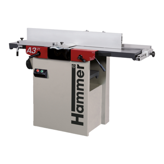
Summary of Contents for Felder A3-31
- Page 1 A3-31 Adjustment Guide...
- Page 2 There are four panels that can be removed from the top side: two covering the hinges, and two covering the kip levers.
- Page 3 To access the adjustment bolts on the hinges, remove the back panel comprising of nine screws. (Two screws are not shown as they are locat- ed on the opposing side)
- Page 4 Loosen bolt (indicated above) to adjust the outfeed table up and down. Adjust table, using wrench, until bolt is set within the middle of its guide.
- Page 5 Loosen the four bolts and use the two worm screws to adjust the height of tables.
- Page 6 Use the four set screws on the hinge-pin to make fine adjust- ments and to make the infeed and outfeed tables parallel to the cutterblock.
- Page 7 Adjust the castle nuts in relation to the hinge adjustments so that the cast-iron tables are even across the cutter block.
- Page 8 Place the straightedge on the cutter block assembly and con- firm that the tables are coplanar with the cutter block assem- bly.
- Page 9 Measure the cast-iron to the cutterblock on the hinge-side first and the front side second. NOTE: After each adjustment, open and close the tables, and re- check measurements.
- Page 10 Once the outfeed table is level and parallel to the cutter block, use a straightedge to level the infeed table.
Need help?
Do you have a question about the A3-31 and is the answer not in the manual?
Questions and answers