Table of Contents
Advertisement
Quick Links
For specialist technical operation
ROTEX Solaris
Solar heating system
Operating and installation
manual
Valid for the following components
ROTEX Solaris Version 3.0 and higher
Solaris R3 temperature difference controller
Sanicube Solaris storage tank
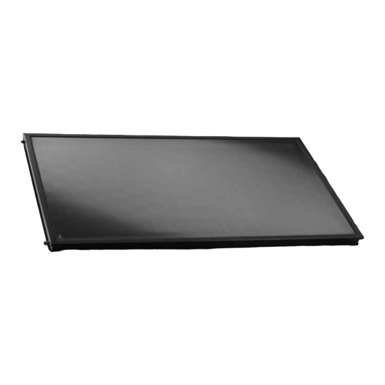
Solaris flat solar panel
Serial number
Customer
GB
Issue 08/2007
Advertisement
Table of Contents

Subscribe to Our Youtube Channel
Related Manuals for Rotex Solaris

Summary of Contents for Rotex Solaris
- Page 1 For specialist technical operation ROTEX Solaris Solar heating system Operating and installation manual Valid for the following components ROTEX Solaris Version 3.0 and higher Issue 08/2007 Solaris R3 temperature difference controller Sanicube Solaris storage tank Solaris flat solar panel Serial number...
- Page 2 Guarantee ROTEX accepts the guarantee for material and manufacturing defects according to this statement. Within the guarantee period, ROTEX agrees to have the device repaired by a person assigned by the company, free of charge. ROTEX reserves the right to replace the device.
-
Page 3: Table Of Contents
Operating Solaris systems without a FlowSensor ........ - Page 4 Other adjustments of your Solaris system ........
-
Page 5: Safety
Relevant documents The documents listed below are part of the technical documentation of the ROTEX Solaris system and must also be observed. The documents are included in the scope of supply. – ROTEX Solaris: Instruction manual for the operator. -
Page 6: Danger Prevention
ROTEX Solaris systems are built in accordance with the state of the art and generally accepted engineering practice. However, improper use can lead to serious injuries or death, as well as causing material damage. To avoid danger, ROTEX systems should only be installed and operated: –... -
Page 7: Product Description
Product description Design and components of the Solaris system Product description Fig. 2-1 Standard design of a ROTEX Solaris system (ROTEX recommends a two-way connection) Cold water connection pipe Immersion sleeve for Solaris return flow temperature sensor Domestic water (hot) distributor... -
Page 8: Brief Description
The ROTEX Solaris system is a thermal solar system for supplying hot water for consumption and heating support. Method of operation The high-performance Solaris flat solar panels, types V21A, V26A and H26A convert the sunlight into heat with high efficiency. Hereby, the heat transport media is normal tap water. -
Page 9: System Components
Connection pipe with circulation pump, booster pump, filling and draining cock ROTEX Solaris R3 differential temperature control with storage tank temperature sensor, return flow temperature sensor, solar panel temperature sensor connection cable, connection cable for 230 V mains supply (3 m) -
Page 10: Other Mounting Accessories
Fig. 2-6 CON I (optional) CON SX Solaris storage tank extension set ( 16 01 07): for connecting two Sanicube Solaris storage tanks, consisting of a return flow connection pipe and feed connection pipe. Fig. 2-7 CON SX (optional) 2.3.4 Other mounting accessories... - Page 11 – Fixing screws (4x) Fig. 2-9 Rail connector FIX-VB Solaris flat solar panels V21A, V26A and H26A V21A Solar panel ( 16 43 06): – H x B x D: 2000 x 1006 x 95 mm, weight: approx. 34 kg...
-
Page 12: Installation
Installation System concepts Installation ROTEX Solaris installations are usually built according to one of the following system concepts. Fig. 3-1 Solaris solar panel array with connections on same side, Fig. 3-2 Solaris solar panel array with connections on same side,... -
Page 13: Installing The Control And Pump Unit
Step 3 1. Remove the storage tank handle and unscrew the sealing cap of the Solaris return flow connection. 2. Use the previously removed handle screws to attach the pump holding bracket to the upper plastic inserts of the handle fixture. - Page 14 Fig. 3-16 Step 11 Fig. 3-17 Step 12 12. Prepare the feed pipe using the sensor cable (VA 15 Solar) and return flow pipe (VA 18 Solar). Cut the Twin heat insulation open in the middle. FA ROTEX Solaris - 08/2007...
- Page 15 Fig. 3-23 Step 3 The automatic speed regulation of the control and pump unit can only work if a FlowSensor is included in the system. If not, the circulation pump will run continuously at 100 %. FA ROTEX Solaris - 08/2007...
- Page 16 3. Fix the hood with the storage tank connection angle below it. To do that, carefully insert the tapping screw (supplied) through the recess in the lower part of the housing front side and then plug in the cover cap. FA ROTEX Solaris - 08/2007...
-
Page 17: Installing The Sensors
The measuring ranges are 0...20 l/min (flow quantity) and 0...120 °C (feed temperature). Both values are indicated on the Solaris R3 control unit. By controlling the speed of the circulation pump, the Solaris R3 automatically adjusts the optimum flow quantity. -
Page 18: Installing The Temperature Sensor
2. Align return flow sensor in the sensor tube to approx. 130 cm insertion depth (cable binder). 3. Align storage tank sensor in the sensor tube to approx. 70 cm insertion depth (cable binder). 4. Push the sealing plug into the sensor tube and route the cables. Fig. 3-41 Step 4 FA ROTEX Solaris - 08/2007... -
Page 19: Installing The Connection Pipes
4. Connect the feed (at the top of the solar panel/VA 15 Solar) or outflow connection pipe (at the bottom of the solar panel/VA 18 Solar) to the connection pipe (Fig. 3-44). Fig. 3-42 Mark the connection pipe Fig. 3-43 Shorten it to length Fig. 3-44 Push the fitting onto the coupling FA ROTEX Solaris - 08/2007... -
Page 20: Connect Several Sanicube Hot Water Storage Tanks
After connecting and starting the system, the filling levels should be observed for at least 2 hours and the FlowGuards adjusted if necessary. The ROTEX connection pipe system permits the parallel connection of several Solaris Sanicube to obtain large-scale installations with and without solar heating. -
Page 21: Installing The Common Return Flow Pipe
(see page 13 steps 4 and 5). 5. Fit the removed part to the return flow connection pipe premounted by ROTEX on the 2nd storage tank connection. -
Page 22: Installing The Solar Panel Components
Frost or overheating can damage the system. • Permit the system to drain. Make sure that the solar panels are installed so that their lower edge is always higher than the feed coupling of the Solaris storage container. Notes for safe and trouble-free operation •... -
Page 23: Installing The Supporting Structure For Subsequent Installation On The Roof
Instead of the mounting kit FIX-AD, the roof fixtures FIX-WD ( 16 47 03) are used for corrugated roofs and the fixtures FIX-BD ( 16 47 04) for trapezoidal roofs. Main dimensions of Solaris solar panel array for on-roof mounting Number of solar panels Measurement Dim. - Page 24 Installation Fig. 3-47 Main dimensions of a Solaris solar panel array for on-roof mounting (example shows V26A solar panels) Roof mounting bracket Solaris V26 flat solar panel Solar panel drain plug Mounting rail Return flow connection pipe Universal roof duct...
- Page 25 6. Place the mounting rail on the perforated plates and align the mounting brackets parallel to the roof tiles. 7. Fix every roof mounting bracket to a rafter with at least 2 of the wood screws supplied (Fig. 3-51). FA ROTEX Solaris - 08/2007...
- Page 26 Make sure that the upper and lower mounting rails provide a plane-parallel mounting surface for the solar panels. Loosley tighten the self-locking nuts of the slide blocks in the upper mounting rails, so that the rail can be levelled out precisely after mounting the first solar panel. FA ROTEX Solaris - 08/2007...
-
Page 27: Installing The Supporting Structure For Subsequent Installation On A Flat Roof
Mounting the upper rails (see Table 3-1 for dimension) 3.4.2 Installing the supporting structure for subsequent installation on a flat roof More detailed information can be found in the installation manual entitled "ROTEX Solaris installation on a flat roof", supplied with the installation system. -
Page 28: Installing The Other Solar Panels
Push the fitting onto the coupling Fig. 3-66 Positioning the next solar panel 3. Lift the next solar panel onto the mounting rails (see Section 3.4.4, step 2) and lower into the securing clips at a distance from the fittings (Fig. 3-66). FA ROTEX Solaris - 08/2007... - Page 29 • When pushing the parts together, move the next solar panel upwards slightly or align it with the connection pipes of the previous solar panel. 6. Tighten the dual clip (Fig. 3-69). 7. Insert the mounting clips for the last solar panel and tighten them. FA ROTEX Solaris - 08/2007...
-
Page 30: Installing The Equipotential Bonding Terminal
30 m Pipe extension kits CON X 25 (2.5 m), CON X 50 (5 m), and 17 m CON X 100 (10 m) are available. 15 m Tab. 3-2 Lengthening options with CON X connection pipes FA ROTEX Solaris - 08/2007... - Page 31 • Run the connection pipe with a continuous gradient between the solar panels and the storage tank. • Install and connect the pipe to the lower coupling of the Solaris Sanicube as described in Chapter 3.3. • Connect the solar panel array alternately and align it so that the bottom return flow coupling is located at the lowest point of the solar panel array.
- Page 32 (Fig. 3-80). Fig. 3-78 Cutting the connection pipe Fig. 3-79 Compressing the insulating Fig. 3-80 Pushing the insulation sleeve to the required length sleeve and mounting the fitting over the fitting FA ROTEX Solaris - 08/2007...
-
Page 33: Installing The Solar Panel Temperature Sensor
• When securing the cable, make sure that no rainwater can run down the cable to the sensor insertion point. Fig. 3-81 Cutting off the well cover Fig. 3-82 Inserting the temperature Fig. 3-83 Secure the sensor cable sensor up to the specified depth in with cable ties the well FA ROTEX Solaris - 08/2007... -
Page 34: Uninstalling The Solar Panels
4. For pipe runs in which only a limited gradient can be achieved, copper pipe may be used on site. This avoids the need for a rigid supporting structure and prevents the formation of water pockets due to expansion of the plastic pipes. FA ROTEX Solaris - 08/2007... -
Page 35: Start-Up
8. Check the filling level in the Solaris Sanicube. Within a few minutes, the level indicator in the Solaris Sanicube must show a level that is slightly lower than before. The reason for this is the presence of a small amount of water remaining in the lower pipes of the solar panels. -
Page 36: Operation Of Solaris Systems With A Flowsensor
• Fill the storage container via the filling & draining cock on the RPS3 until water comes out of the safety overflow. • Close the filling & draining cock. 2. Switch on the Solaris R3 control unit (initialising phase starts). 3. When the initialising phase is complete (temperature display), you can vent the system by simultaneously pressing both arrow keys (starts the manual operating mode). - Page 37 During normal operation (circulation pump on/booster pump off) the value per solar panel should be about 90 to 120 l/h (1.5 to 2.0 l/min). 9. Only if the RPS3 control unit is connected to two Solaris Sanicubes via a common return flow pipe (storage tank extension set CON SX): –...
-
Page 38: Control
Controller operating principle The Solaris system is operated throughout the year, without the need for manual intervention. Speed-controlled pump operation is regulated by the Solaris R3 temperature difference controller. The operating and display elements are shown in Fig. 5-1. 5.2.1 Pump operation Pump operation includes the following functions: –... -
Page 39: Booster Function For High Solar Panel Temperatures
With solar panel temperatures above 100 °C, the return flow water evaporates immediately as soon as it enters the solar panel. In a correctly installed Solaris system, the steam escapes into the storage tank, where most of it condenses again. It is possible that a reduction of the excess heating capacity in the solar panels and the associated boiling noise will take several minutes. -
Page 40: Solaris Flowsensor
If the temperature difference is too small, pump output is reduced. While pump P1 is running, its instantaneous output "Flow" is displayed as a percentage next to the measured flow value. Fig. 5-2 shows the typical operating curve of a Solaris system with modulated pump control. Solar panel temperature Frost protection temperature ("TR frost") -
Page 41: Overall Reset Function
5.2.10 Frost protection function In case of low outdoor temperatures, the Solaris system is started only if the operating conditions for a factory-defined frost protection temperature of 25 °C ("TR frost") for the return flow are fulfilled. If the measured return flow temperature is below the frost protection value ("TR frost"), the pumps are operated at least for the period defined in parameter "Time P2", even if... -
Page 42: Adjustments And Menu Guidance
5.3.1 Display during start-up After switch-on, the Solaris R3 control unit goes through a self-testing routine, during which all the display elements and the adjustment parameters are shown separately. The following testing steps are carried out and the results are displayed for about 2 seconds (Fig. -
Page 43: Display During Operation
5.3.2 Display during operation During operation, the display shows the system temperatures, maximum values and calculated values. After showing the start display, the Solaris R3 controller switches automatically to operation display mode, an operation value is displayed and the relevant light is illuminated. - Page 44 Control unit operation Fig. 5-6 Set-up menu FA ROTEX Solaris - 08/2007...
-
Page 45: Password Protection
Operator password When delivered, this password is not activated in the Solaris R3 control unit. By entering a 4-digit number code, all the parameters adjustable in Operator level are protected against unauthorised access (child protection or caretaker function). The parameters of the Operator level can only be changed with the correct Operator password or if password protection has been disabled. -
Page 46: Language Selection
16 41 10) is required, which is available as an accessory. If the Solaris system reaches an instantaneous output value (adjustable by an expert via menu item Selection 1\2\ Parameter selection\Operating parameter "P min") or if the storage tank is heated to a minimum temperature (adjustable by an expert via operating parameter "TS min"... -
Page 47: Recommended Settings
System switch-on involving steam generation can often be disconcerting for the operator. Therefore, the switch-on inhibit temperature "TK perm" has been factory-set to 95 °C, which prevents boiling noises and escaping steam. The Solaris control unit switches on the pumps again only when the solar panel temperature has fallen 2 Kelvin below the adjusted parameter value. -
Page 48: Recommended Settings For Auxiliary Heating Via External Heat Sources Or The Electric Heater, Burner Inhibit Contact
For the highest performance potential: • Rarely with Sanicube Solaris and only up to an adequate temperature, by means of an external heat source or the electric heater. • Via a timer program for "normal use", with optimal times determined from observing regular consumption behaviour. -
Page 49: Tips For Optimised User Behaviour
• Start filling the bathtub only with hot water. After the 25 l of hot water stored in the Sanicube Solaris have been drawn, the hot water discharge temperature drops slightly and the water is mixed in the bathtub. In this way, the storage capacity is used in an optimal manner with a minimum charging temperature;... -
Page 50: Faults And Disturbances
Sensor-specific error messages With a break or short circuit in a sensor or sensor cable, the Solaris control unit reacts as follows (see Table 6-2): – A blinking code letter in the status line indicates the fault and an error message is generated. -
Page 51: Troubleshooting
P1 and P2 are started (Fig. 5-3). Pumps are switched off. The letter "F" blinks in the status line of the Solaris control unit. • Investigate for a possible leak in the Solaris system, rectify the problem and finally restart the system by switching off/on the control unit. - Page 52 Faults and disturbances If steam escapes continuously from the Solaris Sanicube during solar radiation, the flow is too low. • In this case, the system settings must be checked. Special notes on electric sensors WARNING! An electric shock can cause severe burns and fatal injuries. Therefore, before opening the control unit housing, the mains supply must be disconnected and secured against restart.
-
Page 53: Hydraulic System Integration
The second stainless steel corrugated pipe exchanger in the Sanicube Solaris can transfer approx. 1.0 kW per Kelvin excess temperature compared with the average temperature in the hot water area of the storage tank. - Page 54 The second stainless steel corrugated pipe exchanger in the Sanicube Solaris can transfer approx. 1.0 kW per Kelvin excess temperature compared with the average temperature in the bottom half of the storage tank.
- Page 55 The heat exchanger is manufactured of high-grade stainless steel (1.4404). If the swimming pool water is to be heated directly in the exchanger, the corrosion resistance must be checked on site. In case of doubt, the systems must be separated. FA ROTEX Solaris - 08/2007...
- Page 56 Hydraulic system integration Fig. 7-6 GasSolarUnit Standard (GSU) Fig. 7-7 Wood-fired boiler combined with a GasSolarUnit (GSU) * Disconnecting the standard connection: 3-way reversing valve UV1 must be removed and then reconnected outside the device. FA ROTEX Solaris - 08/2007...
- Page 57 Hydraulic system integration Fig. 7-8 Parallel connection of a Solaris (SCS 538/16/0) and a GasSolarUnit (GSU) with increased proportion of solar heating * Disconnecting the standard connection: 3-way reversing valve UV1 must be removed and then reconnected outside the device.
- Page 58 Pressurised solar system with a GasSolarUnit (GSU) * RPS3 must be modified; to do this, dismantle P and use as solar centrifugal pump (electrical connection parallel to the P Fig. 7-11 E-Solar Unit Standard (ESU 509) FA ROTEX Solaris - 08/2007...
- Page 59 Hydraulic system integration Name Meaning Remark Order No. SCS 538/16/0 Solaris Sanicube INOX (1 charging heat exchanger) 16 45 16 SCS 538/16/16 Solaris Sanicube INOX (2 charging heat exchangers) 16 45 17 SCS 538/0/0 Sanicube Solaris INOX 16 45 15...
- Page 60 For this, the booster pump must be connected in parallel with the circulation pump P1. • Operate the solar system with the Solaris control unit. For this, a solar panel temperature sensor with a Pt 1000 element is required (can be ordered optional).
-
Page 61: Technical Data
The solar panel is permanently standstill proof and thermo-shock tested. Minimum solar panel yield above 525 kWh/m per year with 40 % cloud coverage (location Würzburg) Tab. 8-1 Technical data of Solaris V26 flat solar panel Control and pump unit RPS3 Dimensions W x D x H 280 x 280 x 1000 cm... - Page 62 Burner inhibit contact Power Mains supply Storage tank temperature sensor Technical data of the E-Solar Unit, Gas Solar Unit, and Sanicube series are given in the ROTEX price list and the corresponding technical documents of the products. FA ROTEX Solaris - 08/2007...
-
Page 63: List Of Keywords
Connection pipe ....19 Connection pipe Solaris ... 10 CON A ..... . 9 Rail connector FIX-VB . - Page 64 FA ROTEX Solaris - 08/2007...
Need help?
Do you have a question about the Solaris and is the answer not in the manual?
Questions and answers
why is the letter W aways blinking