
Related Manuals for PlayNation Play Systems Tahoe Space Saver


Summary of Contents for PlayNation Play Systems Tahoe Space Saver
- Page 1 Tahoe Space Saver ASSEMBLY MANUAL Copyright © 2010 PlayNation Play Systems, Inc. All Rights Reserved www.PlayNation.com • 190 Etowah Industrial Court • Canton, GA 30114 • (800) 661-7295 Latest Revision: November 24, 2010...
- Page 2 TABLE OF CONTENTS Warranty and Safety Guidelines……………………………………..…..……...Pages 3-10 Leveling You Playset, General Information, Definitions and Site Plan..Pages 10- 14 Kit Contents and Tool List…………..………………………………………....Page 15 Hardware, Lumber and Accessory Checklist..……………………………..Pages 16-20 Framing Fort……………………………………..…………………………..……..Steps 1-3 Mounting Deck Supports…………………………..……………….…………...…..Step 4 Attaching Center Posts……………..…………………...…..……..……...….……..
-
Page 3: Important - Please Read
IF YOU HAVE MISSING OR DAMAGED PARTS OR NEED ASSISTANCE ASSEMBLING, PLEASE CALL PlayNation Play Systems, Inc. MANUFACTURING DIRECT.(800) 445-7529 FACTORY HOURS – MON.–FRI., 8AM-5PM EST DO NOT RETURN THIS PRODUCT TO THE RETAILER OR CONTACT THE RETAILER DIRECT. - Page 4 Thank you for choosing Playnation Play Systems, Inc. We’ve included everything you need, except tools, to build your very own professional looking play set. When complete, your new play set should far exceed the quality of play set kits from other build-your-own companies. Our engineers and design team have over 30 years of playground experience.
- Page 5 Limited Manufacturers Warranty PlayNation Play Systems, Inc. (“PlayNation”) warrants its play sets to be free from defects in workmanship and materials, under normal use and conditions at its original installation, for 10 years for structural wood components and for one year for all other components (e.g., hardware, plastics, tarps, rope ladder, etc.)
- Page 6 Adult supervision is recommended anytime a play set is being used. WEIGHT LIMITS FOR PlayNation Play Systems • FORT PLATFORMS: 800 LBS. TOTAL WEIGHT • SWING BELTS: 175 LBS.
- Page 7 Safety and Maintenance Tips for Your New Play Set: NOTE: Your children’s safety is our #1 concern. Observing the following statements and warnings reduces the likelihood of serious or fatal injury. Please review these safety rules regularly with your children. •...
- Page 8 Safety and Maintenance Tips for Your New Play Set: (continued) Playgrounds should be inspected on a regular basis. If any of the following conditions are noted, they should be removed, corrected, or repaired immediately to prevent injuries. • Hardware that is loose, worn or that has protrusions or projections. •...
- Page 9 Play Set Surfacing Recommendations: Below are some of the recommendations that the U.S. Consumer Product Safety Commission (CPSC) offers from its Handbook for Public Playground Safety. The guide can be downloaded in full at www.cpsc.gov/cpscpub/pubs/325.pdf 1. Protective Surfacing - Since almost 60% of all injuries are caused by falls to the ground, protective surfacing under and around all playground equipment is the most critical safety factor on playgrounds.
- Page 10 2. Fall Zones - A fall zone, covered with a protective surfacing material, is essential under and around equipment where a child might fall. This area should be free of other equipment and obstacles onto which a child might fall. Stationary climbing equipment and slides should have a fall zone extending a Minimum of 6’...
- Page 11 General Info to Review Before Installation • Depending on your experience, assembly of PlayNation Playsets can take as little as 6 hours up to 24 hours, depending on size, after inventory of parts; therefore, we recommend you set aside a full two days for assembly. •...
- Page 12 This page is a list of definitions and explanations used throughout our instructions to aid you in the assembly of your play set. Offset Holes- Throughout the installation procedures we will refer to parts with offset holes. This refers to the orientation of the holes on the board. An offset hole is one that is closer to one side than it is to the other or in other words, it is not centered on the board.
- Page 13 Common Installation Practice Installing T-nuts When installing T-nuts into the wood, use a smooth faced hammer to set the face of the T-nut flush into the wood Corner Post Insert the barrel of the T-nut into the T-nut predrilled hole. Using a smooth faced hammer, drive the T-nut until the face of the T-nut is flush to the wood.
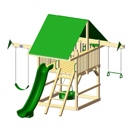
- Page 14 Please familiarize yourself with the manual, parts/components and general con- struction process of your new playset before getting started. SITE PLAN: 76.75 38.25 Trapeze Arm (1) 120.75 Swing Belts (1) 38.25 18.25 Ladder 54.75 Scoop Slide Playset height: 11-1/2 feet Approximate assembly time: 6-8 Hours 6 foot unobstructed safety perimeter around playset recommended Page 14...
-
Page 15: Required Tool List
KIT CONTENTS Swings, Slides, Accessories: ___ (Qty ) Description ___ (1) Swingbelts w/ Chains ___ (1) 10ft. Scoop Slide ___ (1) Tahoe Space Saver Assembly Manual ___ (1) Trapeze Swing ___ (1) Telescope ___ (1) Steering Wheel ___ (2) Safety Handles... - Page 16 3/8 X 3-1/2" 3/8 X 5" HEX LAG SCREW HEX LAG SCREW QTY: 42 QTY: 42 #8 X 2" WOOD SCREW QTY: 70 #8 X 2-1/2" WOOD SCREW QTY: 36 3/8" LOCK NUT QTY: 26 3/8" WASHER QTY: 110 TORQUE WASHER QTY: 26 #2 SQUARE DRILL BIT...
-
Page 17: Description Qty
PICTURE DESCRIPTION QTY. 2 X 4 X 70" CENTER DECK SUPPORT 2 X 4 X 70" SAFETY BOARD/ CENTER TARP BOARD 2 X 4 X 77" END TARP BOARD 2 X 6 X 70" SANDBOX/FILLER BOARD 4 X 4 X 16" FORT SUPPORT (LEFT) 4 X 4 X 16"... - Page 18 PICTURE DESCRIPTION QTY. 4 X 4 X 62-3/4" TIRE SWING SUPPORT 4 X 4 X 70" BLOCK SUPPORT 4 X 4 X 70" DECK SUPPORT 4 X 4 X 84" CENTER POST 4 X 4 X 96" CORNER POST 4 X 4 X 118" SIDE RAIL 4 X 6 X 38"...
- Page 19 PICTURE DESCRIPTION QTY. 4 X 6 X 115" TRAPEZE ARM 5/4 X 6 X 63-1/2" CENTER DECK BOARD 2-3/8" X 16-7/8" X 69-1/2" DECK PANEL (3 BOARD) 2-3/8" X 11-1/4" X 69-1/2" DECK PANEL (2 BOARD) 4-3/4" X 29" X 76" LADDER 3-3/8"...
- Page 20 PICTURE DESCRIPTION QTY. TIRE SWIVEL 11-4010 SCOOP SLIDE 03-0005 SPRING CLIP 11-4003 IRON DUCTILE 11-4012 STEERING WHEEL 07-0004 TELESCOPE 07-0001 SAFETY HANDLE 08-0001...
- Page 21 PICTURE DESCRIPTION QTY. PLASTIC FLAG KIT (PAIR) 09-1007 SWING BELT W/CHAINS 04-0002 TRAPEZE BAR W/CHAINS 04-0005 TIRE SWING W/CHAINS 04-0015 TARP WITH SNAPS 05-1009...
-
Page 22: Step 1: Corner Posts
STEP 1: CORNER POSTS 1: PLACE ONE 2 X 6 X 70" SANDBOX BOARD, OFFSET HOLES UP, FLUSH WITH THE BOTTOM OF TWO 4 X 4 X 96" CORNER POSTS ON THE SIDE WITH ONE THROUGH HOLE. FASTEN THE SANDBOX BOARD TO THE CORNER POSTS WITH 3/8 X 3 1/2" LAG SCREWS AND 3/8" WASHERS. 2: REPEAT THIS PROCESS FOR THE OPPOSITE SIDE. - Page 23 STEP 2: BLOCK SUPPORTS 1: INSTALL THE 4 X 4 X 70" BLOCK SUPPORTS TO THE CORNER POSTS AT THE 51-1/2" HOLE. 2: FASTEN THE BLOCK SUPPORTS TO THE CORNER POSTS FROM THE OUTSIDE USING 6-1/2" CARRIAGE BOLTS WITH TORQUE WASHERS AND 3/8" WASHERS AND 3/8" LOCK NUTS ON THE INSIDE.
- Page 24 STEP 3: SANDBOX BOARDS 1: PLACE TWO 2 X 6 X 70" SANDBOX BOARDS, OFFSET HOLES DOWN, FLUSH TO THE BOTTOM OF THE CORNER POSTS. 2: FASTEN THE SANDBOX BOARDS TO THE CORNER POSTS WITH 3/8" X 3-1/2" LAG SCREWS AND 3/8"...
-
Page 25: Step 4: Deck Supports
STEP 4: DECK SUPPORTS 1: PLACE THE 4 X 4 X 70" DECK SUPPORTS ON TOP OF THE BLOCK SUPPORTS. FASTEN THE DECK SUPPORTS TO THE CORNER POSTS WITH 3/8" X 5" LAG SCREWS AND 3/8" WASHERS FROM THE INSIDE. 2: FASTEN THE DECK SUPPORTS TO THE BLOCK SUPPORTS WITH 3/8"... - Page 26 STEP 5: CENTER POSTS 1: PLACE THE 4 X 4 X 84" CENTER POSTS FLUSH WITH THE BOTTOM OF THE BLOCK SUPPORTS, LINING UP THE PILOT HOLES AT THE CENTER OF THE BLOCK SUPPORTS. 2: FASTEN THE CENTER POSTS TO THE BLOCK SUPPORTS USING 6-1/2" CARRIAGE BOLTS WITH TORQUE WASHERS ON THE OUTSIDE AND 3/8"...
- Page 27 STEP 6: TIRE SWING SUPPORT 1: PLACE THE 4 X 4 X 62-3/4" TIRE SWING SUPPORT FLUSH ON TOP OF THE BLOCK SUPPORTS, IN LINE WITH THE CENTER POSTS. NO SCREWS ARE NEEDED FOR THE TIRE SWING SUPPORT. 2: PLACE THE 2 X 4 X 70" CENTER DECK SUPPORTS FLUSH AGAINST THE CENTER POSTS, ON TOP OF THE BLOCK SUPPORTS.
- Page 28 STEP 7: BLOCKS AND TIRE SWIVEL 1: PLACE THE 4 X 4 X 25" BLOCKS FLUSH ON TOP OF THE BLOCK SUPPORTS, BETWEEN THE CENTER AND END DECK SUPPORTS. FASTEN THE BLOCKS TO THE BLOCK SUPPORTS WITH 3/8" X 5" LAG SCREWS AND 3/8" WASHERS. 2: PLACE THE TIRE SWIVEL ON TOP OF THE TIRE SWING SUPPORT, ON CENTER.
- Page 29 STEP 8: DECK PANELS 1: PLACE ONE 3-BOARD DECK PANEL ON TOP OF THE DECK SUPPORTS, IN FRONT OF EACH OF THE CENTER POSTS, ALLOWING THE 2 X 4 DECK STRINGERS ON THE END OF THE DECK PANELS TO OVERLAP THE DECK SUPPORTS. 2: PLACE A 2-BOARD DECK PANEL BESIDE OF THE 3-BOARD DECK PANELS.
- Page 30 STEP 9: END CENTER POSTS 1: PLACE THE 4 X 6 X 38" END CENTER POST AGAINST THE DECK SUPPORTS AND LINE UP THE PILOT HOLES. THE COUNTER-BORED HOLE IN THE CENTER POST SHOULD FACE THE INSIDE OF THE PLAY SET.
- Page 31 STEP 10: CENTER DECK BOARD 1: PLACE THE 5/4 X 6 X 63" CENTER DECK BOARD ACROSS THE TOP OF THE DECK SUPPORTS, BETWEEN THE 2-BOARD DECKS. 2: SECURE THE CENTER DECK BOARD TO THE DECK SUPPORTS WITH SIX 2" WOOD SCREWS. 5/4 X 6 X 63"...
-
Page 32: Step 11: Side Rails
STEP 11: SIDE RAILS 1: INSTALL THE 4 X 4 X 118" SIDE RAILS TO THE CORNER POSTS AT THE 86" HOLE. FASTEN THE SIDE RAILS USING 3/8" X 6-1/2" CARRIAGE BOLTS WITH TORQUE WASHERS FROM THE INSIDE, AND 3/8" LOCK NUTS AND 3/8" WASHERS ON THE OUTSIDE. 2: MAKE SURE THE CENTER POSTS AND SIDE RAILS ARE SQUARE. - Page 33 STEP 12: TRAPEZE ARMS 1: PLACE THE 4 X 6 X 115" TRAPEZE ARM ON TOP OF THE SIDE RAILS FLUSH TO THE CORNER POSTS. WITH A 3/8" DRILL BIT, DRILL A HOLE THROUGH THE 4 X 6 X 115" TRAPEZE ARMS AND THE CORRESPONDING CORNER POSTS.
- Page 34 STEP 13: LADDER 1: ATTACH THE PRE-ASSEMBLED LADDER TO THE END CENTER AND CORNER POSTS IN THE FRONT RIGHT OPENING ON THE FRONT OF THE PLAY SET. FASTEN THE LADDER TO THE END CENTER AND CORNER POSTS USING 3/8" X 5" LAG SCREWS AND 3/8" WASHERS FROM THE INSIDE OF THE LADDER RAILS.
- Page 35 STEP 14: PANELS 1: PLACE THE FOUR PRE-ASSEMBLED SIDE PANELS ON TOP OF THE DECK SUPPORT AND CENTER DECK SUPPORTS. SEE BELOW FOR DETAILS. ATTACH BOTTOM OF EACH PANEL TO DECK SUPPORTS WITH FOUR 2-1/2" WOOD SCREWS. 2: FASTEN TOP OF SIDE PANELS TO THE SIDE RAILS WITH 3/8" X 5" LAG SCREWS AND 3/8" WASHERS.
- Page 36 STEP 15: TARP BOARDS 1: LOCATE TWO 2 X 4 X 77" END TARP BOARDS AND ONE 2 X 4 X 70" CENTER TARP BOARD. 2: PLACE THE 2 X 4 X 77" END TARP BOARDS AT THE ENDS OF THE SIDE RAILS AND ATTACH EACH BOARD WITH TWO 3/8"...
- Page 37 STEP 16: TARP 1: LAY THE TARP ACROSS THE CENTER TARP BOARD AND END TARP BOARDS. 2: CENTER THE TARP ACROSS THE BOARDS AND MARK THE LOCATION OF THE TARP SNAPS WITH A PENCIL ONTO THE END TARP BOARDS. 3: (SEE BALLOON 1 BELOW) FASTEN A SNAP SCREW (INCLUDED WITH THE TARP) AT THE FRONT LEFT CORNER ON THE MARK THAT WAS MADE.
- Page 38 STEP 17: SLIDE PLACE THE SCOOP SLIDE ON TOP OF THE DECK, OVERLAPPING THE DECK BOARDS. ATTACH THE SCOOP SLIDE TO THE DECK WITH 1-1/4" PAN HEAD WOOD SCREWS. SCOOP SLIDE LADDER...
- Page 39 STEP 18: FILLER BOARD PLACE THE 2 X 6 X 70" FILLER BOARD WITH OFFSET HOLES DOWN FLUSH TO THE TOP OF THE DECK BOARDS. ATTACH TO THE CORNER POSTS WITH 3-1/2" LAG SCREWS AND 3/8" WASHERS. 3-1/2" LAG SCREW 3/8"...
- Page 40 STEP 19: SWINGS 1: FASTEN THE IRON DUCTILES TO THE BOTTOM OF THE TRAPEZE ARMS USING 3/8" X 6-1/2" CARRIAGE BOLTS WITH TORQUE WASHERS ON TOP OF THE BEAM, AND 3/8" WASHERS AND 3/8" LOCK NUTS ON THE BOTTOM. 2: HANG THE TRAPEZE ARM AND SWING FROM THE IRON DUCTILES USING TWO SPRING CLIPS. HANG THE TIRE SWING FROM THE TIRE SWIVEL USING THREE SPRING CLIPS.
- Page 41 STEP 20: FORT SUPPORTS 1: PLACE THE 4 X 4 X 16" FORT SUPPORTS WITH COUNTER-SUNK HOLES FACING OUT ON THE CORNER POSTS. THE 45 END SHOULD BE AGAINST THE CORNER POST, AND THE OTHER SHOULD BE LEVEL TO THE TOP OF THE BLOCK SUPPORTS. SEE BELOW FOR CLARIFICATION. 2: FASTEN THE FORT SUPPORTS TO THE BLOCK SUPPORTS WITH 5"...
-
Page 42: Step 21: Safety Boards
STEP 21: SAFETY BOARDS PLACE THE 2 X 4 X 70" SAFETY BOARD ON THE CORNER POSTS ON THE SIDES WITH SWINGS 30" FROM THE GROUND. ATTACH THE SAFETY BOARDS TO THE CORNER POSTS WITH 3-1/2" LAG SCREWS AND 3/8" WASHERS. 3/8"... -
Page 43: Step 22: Steering Wheel
STEP 22: STEERING WHEEL 1: PLACE THE STEERING WHEEL INSERT INSIDE THE STEERING WHEEL. 2: USE THE HARDWARE INCLUDED WITH THE STEERING WHEEL TO MOUNT THE STEERING WHEEL TO THE 4 X 4 CENTER POST. DO NOT OVER-TIGHTEN THE LAG SCREW INTO THE STEERING WHEEL, OR IT WILL NOT TURN. - Page 44 STEP 23: TELESCOPE 1: WITH THE 1-1/4" WOOD SCREWS PROVIDED IN THE TELESCOPE BAG, FASTEN ONE OF THE CIRCLE TELESCOPE BRACKETS ONTO THE SIDE RAIL. 2: PLACE THE TELESCOPE STAND AND TELESCOPE INTO THE SLOT OF THE TELESCOPE BRACKET. 3: FASTEN THE REMAINING TELESCOPE BRACKET TO THE OPPOSITE SIDE THAT THE FIRST TELESCOPE BRACKET WAS INSTALLED ON WITH 1-1/4"...
-
Page 45: Step 24: Safety Handles
STEP 24: SAFETY HANDLES 1: PLACE THE SAFETY HANDLES ABOVE THE BASE OF THE ENTRY, CENTERED ON THE CORNER POSTS AND THE 4 X 6 CENTER POSTS. 2: ATTACH THE SAFETY HANDLES TO THE CORNER AND CENTER POSTS WITH 1-1/4" PAN HEAD SCREWS. - Page 46 STEP 25: FLAG KITS 1: THE PLASTIC FLAG KIT CONSISTS OF TWO FLAGS, TWO FLAG BASES AND HARDWARE. ONE FLAG WILL BE INSTALLED ON THE FRONT SIDE OF EACH TRAPEZE BEAM. 2: NO SPECIFIC MEASUREMENT IS NEEDED, BUT THE FLAGBASE MAY BE PLACED 1" FROM THE TOP OF THE BEAM AND 1"...
- Page 47 STEP 26: NAMEPLATE 1: ATTACH THE PlayNation NAMEPLATE CENTERED ON THE FRONT OF YOUR TRAPEZE BEAM WITH TWO 2-1/2" WOOD SCREWS. 2: YOUR PLAYSET IS FINISHED! ENJOY YOUR PLAYSET!
- Page 48 WARRANTY REGISTRATION CARD - Tahoe Space Saver (Tarp Roof) Name: ___________________________________________________________________ Address: __________________________________________________________________ City, State, Zip: ____________________________________________________________ Email: ___________________________________________________________________ Date of Purchase: __________________________________________________________ Place of Purchase: __________________________________________________________ City, State, Zip: ____________________________________________________________ Please, check the boxes below. Your age? 18-25 26-30...
Need help?
Do you have a question about the Tahoe Space Saver and is the answer not in the manual?
Questions and answers