
Related Manuals for Newport NT300


Summary of Contents for Newport NT300
- Page 1 Electric Outboard User’s Manual Please read and retain this manual before using product...
-
Page 2: Table Of Contents
Contents 1 Product Overview . . . . . . . . . . . . . . . . . . . . . . . . . . . . . . . . . . . . . . . . . . 1.1 Product Identification . - Page 3 5.4 Error Codes and Solutions . . . . . . . . . . . . . . . . . . . . . . . . . . . . . . 6 Operation .
-
Page 4: Product Overview
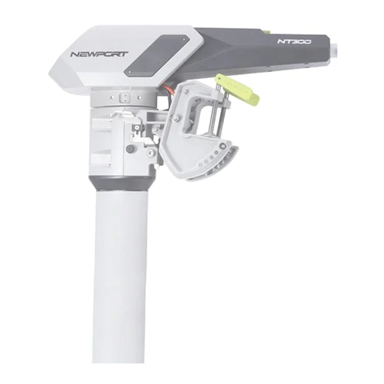
The Newport electric outboard NT300 is designed with direct-drive and field-oriented-control technology to deliver the ultimate efficiency in a compact package. The propulsive power of the NT300 is roughly equivalent to a 3hp petrol outboard motor, but with silent and emission free power delivery. -
Page 5: Technical Data
Technical Data Specification Rated Input Power(static) 1300W Comparable Petrol Outboard 3 HP • Deep cycle marine battery Battery Type • LFP lithium battery • Lithium cobalt oxide battery • 36V-Deep cycle marine battery Battery Input voltage • 36V-LFP Lithium battery •... -
Page 6: Safety Information
Safety Information 3.1 Critical Safety Information Please read all safety information before installing or operating your electric motor. Severe injury, damage, or even death can occur as a result of improper usage. There is a risk of death or severe injury from electric shock- use caution and do not touch any uninsulated wires or damaged parts. - Page 7 There is inherent danger in using a boat- always prepare for the unexpected. A boat which is out of control can easily result in severe injuries or death by drowning. • Always check weather predictions and water conditions before a trip on the water, and also familiarize yourself with a map of the area you’ll be traversing.
-
Page 8: Before Use
Parts may be hot enough to cause burns. Do not touch the components or battery immediately after use; allow to cool sufficiently before handling the components. Danger of crushing when tilting the motor- keep fingers, hands, and all body parts away from mechanical parts and the area of the motor when tilting the motor. -
Page 9: After Use
3.4 After Use • Disconnect the motor from the battery after use. • Flush the motor carefully with freshwater after each usage, especially after use in saltwater. • Do not carry the kayak/boat by lifting with the bracket. This can cause damage to the boat and potentially to the bracket. -
Page 10: Trimming The Motor
2. Tighten the clamp handles to fix the motor on the transom of the boat. 4.2 Trimming the Motor The motor trimming can be adjusted according to the boat type in order to get the optimal position relative to the water surface and better running speed. - Page 11 1. Make sure the reverse lock is pulled up. Reverse Lock 2. Remove the stop ring and pull out the trim pin. Trim Pin...
- Page 12 3. Lift the motor to the stow position. 4. Insert the trim pin to select the desired trim angle, install the stop ring and deploy the motor again. Trim Pin...
-
Page 13: Fixing The Steering
4.3 Fixing the Steering To stop the motor from steering, place the lock pin into the hole. Steering Lock Pin With the lock pin inserted in the hole, now the steering of the motor is fixed. You can use other methods (rudder for example) to steer the boat. -
Page 14: Connect To The Battery
4.4 Connect to the Battery The motor is adaptable with 36V (three 12V batteries connected in series) deep cycle marine battery package, 36V LFP lithium battery (including three 12V LFP lithium batteries connected in series) and 36V lithium cobalt oxide battery package. Please follow the steps below to complete the battery connection. -
Page 15: Controller Display
Controller Display 5.1 Overview of Multi-Function Display The speed controller screen features motor and battery information for the operator to monitor. There are two buttons on the speed controller to control the motor. Battery Voltage Percent Display Battery Voltage Display Battery Type Display Throttle Percent... -
Page 16: Battery Display
5.2 Battery Display 5.2.1 Estimated Percent of Remaining Battery Power The battery bar has 6 different status levels to display the estimated remaining battery percentage. Battery Voltage Percent Display 100% <20% Do not overestimate the remaining battery range; this could result in severe harm or even death. •... -
Page 17: Switching Between Battery Types
5.2.2 Switching Between Battery Types This motor can run on a 36V deep cycle battery setup, a 36V LFP lithium battery setup, or a 36V lithium cobalt oxide battery. Battery Type Display Battery Type Switch Button You will need to select which type of battery you are using with your motor for accurate results on the LCD screen. -
Page 18: Error Status Display
5.3 Error Status Display The icons indicated on the LCD screen above show three possible error statuses of the motor. When a fault occurs, there will be a corresponding code on screen to help diagnose the problem. See section 5.4 Error Codes and Solutions. Motor Overvoltage: If the input voltage is too high, this icon will light Battery Voltage Too Low... -
Page 19: Error Codes And Solutions
5.4 Error Codes and Solutions If there is an issue with the motor function, the display will show an error code to help diagnose the problem and find the solution. Error Description Solution Code The drive PCB is overheated. The motor drive PCB is overheated. Press the Power button for 2 seconds E-01 to reset the system. - Page 20 Error Description Solution Code Motor is overvoltage The voltage of the battery is too high to power the motor, if the battery is normal, make sure to setup correct battery type on the motor. Please follow 5.2.2 Switching Between Battery Types to operate correctly. E-03 Press the Power button for 2 seconds to reset the system and if the voltage...
-
Page 21: Operation
Operation 6.1 Start the Motor To start the motor please follow the steps below: 1. Place the magnet kill switch on the tiller. 2. Select the battery mode according to the battery type used. Please follow 5.2.2 Switching Between Battery Types to operate correctly. -
Page 22: Travel Forward/Reverse
6.2 Travel Forward/Reverse The motor’s forward/reverse motion is controlled by the handle of the tiller. Please refer to the diagram below which demonstrates how to operate. Reverse Neutral Forward When switching to reverse, make sure to push the reverse lock to lock the bracket. -
Page 23: Steering The Motor
6.3 Steering the Motor While the motor is operating, steer the tiller to control the boat direction. -
Page 24: Emergency Stop
6.4 Emergency Stop To stop immediately you can: Pull off the magnetic emergency stop switch from the tiller to stop the motor. Move the handle of the tiller to the neutral position to stop the motor. If you want to restart the motor after the emergency kill switch is pulled off, move the handle of tiller to the neutral position, return the kill switch, and power on. -
Page 25: Finishing The Trip
6.5 Finishing the Trip When the trip is finished, please disconnect the motor from the battery and take the motor out of water. If the motor was used in the saltwater, thoroughly rinse the motor with fresh water. This will help prevent corrosion and salt buildup. -
Page 26: Deploy The Motor
6.7 Deploy the Motor To deploy the motor again, follow the steps below: 1. Lift the motor up. 2. Lift the deploy lever up. Make sure the stand bar is out of the slot. Deploy Lever Stand Bar 3. Tilt the motor down slowly until the trim pin is hit again. -
Page 27: Care And Service
Care and Service 7.1 Care of Motor Components • Please regularly follow all maintenance tips to keep your motor in optimal working condition. • Do not start the motor in shallow water as it may damage the propeller. • After each use, check between the plastic propeller and metal motor housing for fishing line, weeds, or other debris. -
Page 28: Replacing The Fin
7.4 Replacing the Fin You can replace the fin component if it is damaged. To do this, follow the steps below: 1. Release the three M3 screws and nuts. 2. Remove the old fin component. 3. Insert the new fin component. 4. -
Page 29: Replacing The Propeller
7.5 Replacing the Propeller You can replace the propeller if it is damaged. To do this, follow the steps below with the assembly diagram: Washer Washer M12 Nut Drive Pin Propeller 1. Attach the washer. 2. Insert the drive pin into the hole on the motor output shaft. 3. -
Page 30: Recalibrate The Throttle
7.6 Recalibrate the Throttle You can recalibrate the throttle when the throttle display is inaccurate. To do this, follow the steps below: Press and the MODE button for 5 seconds, the controller will enter the throttle recalibration mode. While the screen displays the F icon, move the handle to the full throttle forward position. - Page 31 While the screen displays the N icon, move the handle to the Neutral (middle) position. Press the MODE button again. And the throttle recalibration is complete. To quit the throttle recalibration mode at any steps during the process, press the power button.
-
Page 32: Customer Support
Customer Support If you have questions that are not answered in this manual or your troubleshooting is not successful, please contact Newport Vessels! Our California based customer service team is standing by to assist you. Customer Support Phone: (866)721-0002 E-mail: support@newportvessels.com...
Need help?
Do you have a question about the NT300 and is the answer not in the manual?
Questions and answers